Custom Touch Display Module: A Practical Guide to Capacitive Touch Display Modules
Quick answer: a custom touch display module is a single integrated assembly — cover glass, touch sensor, display panel, optical bonding and driver electronics — built to an equipment manufacturer's own dimensions, brightness, interface and environmental requirements. The capacitive version, also called projected capacitive (PCAP), detects touch through a change in capacitance and supports multi-point gestures. Capacitive touch modules held a 71% share of the global touch screen module market in 2025, while resistive modules accounted for 19% (Business Research Insights, 2025).
This guide is written for buyers, hardware engineers and product managers in the research and evaluation stage — the point where a touchscreen has to be specified, not merely imagined. It explains what a capacitive touch display module contains, where specification decisions usually go wrong, how optical bonding and surface treatment change the result, and how to move from a requirement list to a validated sample.
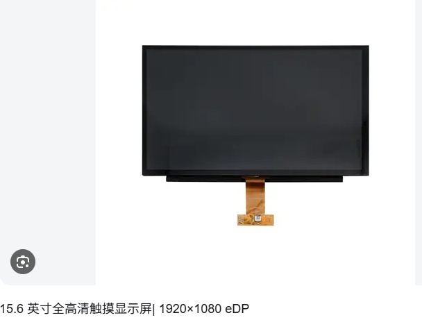
15.6-inch custom capacitive touch display module, model XRCGG156-0186-A0, with G+G glass lens construction and 1920 × RGB × 1080 resolution.
What Is a Capacitive Touch Display Module?
A capacitive touch display module combines three layers of engineering in one part: a capacitive touch panel that senses finger position, a TFT display that renders the image, and the optical bonding and driver electronics that make the two behave as one surface. In a G+G (glass-to-glass) construction — the structure used across the standard models described in this guide — a chemically strengthened cover glass sits above an ITO sensor layer, and both are bonded to the display panel.
The material stack is specific and worth knowing before any quotation is requested. The documented construction uses aluminosilicate chemically strengthened glass as the cover glass, ITO (indium tin oxide) as the touch sensor material, OCA optical adhesive film for optical bonding, plus PVA/TAC film, color filter (CF) and TFT glass substrate for the display side.
A concrete example makes the category easier to hold in mind. Model XRCGG215-0106-A0 is a 21.5-inch capacitive touch display module with a G+G glass lens construction, a 21.5-inch TFT panel at 1920 × RGB × 1080, and 1000 cd/m² brightness. It is designed for industrial control equipment, medical equipment, smart home devices, self-service intelligent service equipment and new energy equipment.
That definition matters commercially because a touch display module is rarely bought off the shelf in the literal sense. Even when a standard model is selected, the buyer is usually customising something — brightness tier, bonding method, surface treatment, cover glass thickness, interface, or the mechanical outline that has to fit an existing enclosure cutout.
The Problem Definition: Why Touch Modules Get Specified Wrong
Most touch module problems are not manufacturing defects. They are specification mismatches that only become visible after the equipment is in the field. Four of them repeat across categories:
1. Brightness selected for the lab, not the location. A module that reads perfectly on a bench can become unreadable beside a window, under a canopy, or in a workshop with strong overhead lighting. Brightness has to be chosen against the actual ambient light of the installation, not the average of a catalogue range.
2. Air gaps left in the stack. When the touch panel and display are not fully bonded, the air gap reduces contrast and creates a space where dust can settle and moisture can condense. This is why lamination method is a specification decision rather than a production detail.
3. Touch technology chosen by habit. Capacitive and resistive solve different problems. Selecting one because it is familiar, rather than because it matches the operating conditions, is the single most common cause of a redesign.
4. Environmental ratings assumed rather than stated. Sealing, impact resistance and operating temperature are frequently treated as implied by the word "industrial". They are not. Each has to appear as a stated value on the drawing or specification sheet.
The practical consequence is that the cheapest route to a working touch interface is an early, explicit requirement list — not a later correction.
Industry Background: Where Capacitive Touch Fits
Capacitive technology is the mainstream choice, but not the only one. According to Business Research Insights, capacitive touch modules held nearly 71% of the global touch screen module market in 2025, with resistive modules at 19%. The gap reflects where consumer and commercial demand sits — multi-point gesture interfaces, flush glass surfaces and higher optical performance — rather than a judgement about which technology is better in every condition.
The commercial touch display market is also expanding. Future Market Insights projects growth from USD 6.9 billion in 2025 to USD 16.3 billion by 2035, a CAGR of 9.0%. Growth of that kind tends to pull in two directions at once: more standardised, price-sensitive modules on one side, and more demanding application-specific requirements on the other.
Standards matter here because buyers increasingly ask for numeric protection claims rather than descriptive ones. The IK rating system, defined in IEC 62262, classifies enclosures by resistance to external mechanical impact. An IK10 rating requires the equipment to withstand 20 joules of impact energy, equivalent to a 5 kg object dropped from 40 cm. When a supplier lists IK10 on a touch display module, that is the threshold being referenced.
The remaining 19% resistive share is not a legacy remnant to be ignored. In workshops where operators wear thick work gloves, where oil and coolant are present, where only single-point input is needed and budgets are tight, a 5-wire resistive touch panel remains a rational engineering answer.
Detailed Solution: What Goes Into a Custom Touch Display Module
Cover Glass and Touch Sensor
The cover glass is the part the user actually touches, so its material and thickness define both durability and feel. Aluminosilicate chemically strengthened glass is used because it resists scratching and local impact better than ordinary soda-lime glass. Cover glass thickness is customisable, with a maximum thickness of 10 mm for applications that need additional mechanical protection.
The sensor layer beneath it uses ITO indium tin oxide to form the capacitive electrode pattern. This is the layer that determines how reliably the module detects a finger — and how well it copes with gloves, moisture on the surface, and electromagnetic noise from surrounding equipment.
Optical Bonding: OCA Full Lamination vs Frame Bonding
Bonding is where two modules with identical components can end up with very different optical performance. The module uses OCA optical adhesive film for optical bonding, which fills the space between the touch panel and the display instead of leaving an air gap.
G+G full lamination is the mainstream option. It delivers higher contrast, has no air gap, and is dustproof and anti-fog — characteristics that matter in medical, cold-chain and semi-outdoor installations. Frame bonding is available as a lower-cost alternative, giving buyers two price tiers for the same nominal product family. The trade-off is straightforward: full lamination costs more and performs better optically; frame bonding reduces cost where the environment is benign and the optical requirement is modest.
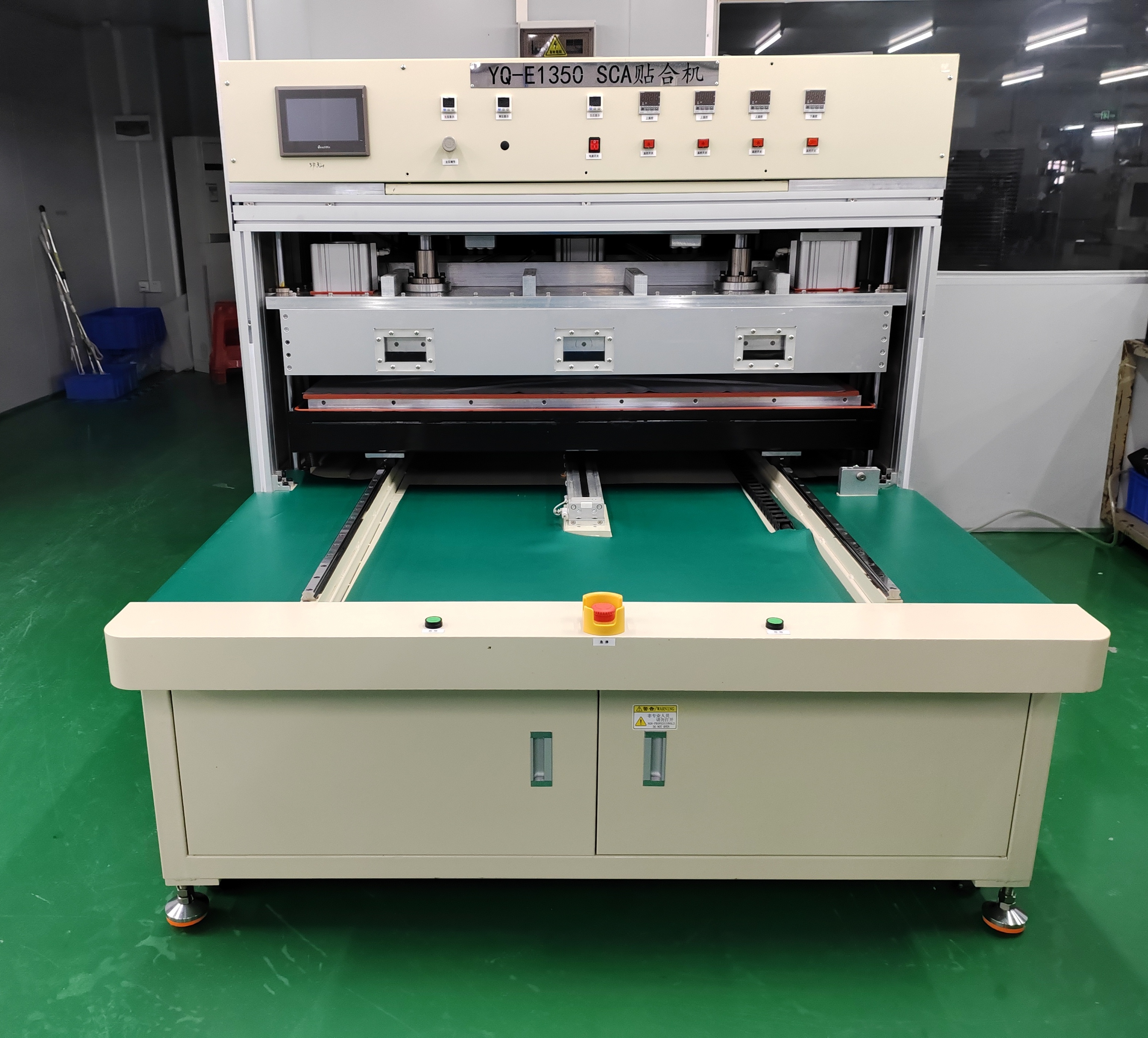
SCA bonding equipment used in the lamination process, where OCA optical adhesive film joins the touch panel to the display.
Surface Treatment: Anti-Glare, Anti-Fingerprint and Anti-Reflection
Three surface treatments can be applied and combined on the cover glass. AF (anti-fingerprint) reduces smearing and makes cleaning easier. AG (anti-glare) diffuses reflected light so the display stays readable under directional lighting. AR (anti-reflection) reduces overall reflection to raise perceived contrast. For an anti-glare touch display module used near windows or in bright rooms, AG is usually the first treatment requested; for medical and public-terminal surfaces, AF tends to matter more because the surface is cleaned frequently.
Touch Performance in Real Operating Conditions
A capacitive touch panel in this range supports 10-point multi-touch with smooth tracking and no drift. Thin-glove touch support is available as an option — a meaningful distinction, because most operators in industrial and medical settings are not bare-handed. ESD protection can be specified to meet industrial EMC requirements in workshops with strong electromagnetic interference.
For self-service terminals, the requirement set is different again: strong resistance to false triggering, tolerance of water stains and rain interference, and support for multiple operation states — bare hand, wet hand and thin glove — plus low drift and a touch-lock function.
Environmental Ratings and Wide-Temperature Operation
The documented modules carry IP68 protection and IK10 impact resistance, with IP68 and IK10 stated as customisable on the 15.6-inch model. Operating temperature is rated from −20°C to +70°C, with storage from −30°C to +80°C. Wide-temperature models in that range suit workshop, cold-chain and charging-pile scenarios.
Brightness is a separate selection axis. The 21.5-inch model is documented with multiple brightness options — a standard 300 cd/m² plus high-brightness versions of 500, 700 and 1000 cd/m² for industrial control, semi-outdoor and outdoor use. The 7-, 10.1-, 13.3- and 15.6-inch models are specified at 700, 800, 1000 and 1000 cd/m² respectively.
Standard Models and What Each One Is For
Five standard capacitive models cover the common equipment formats. All five share the G+G glass lens construction, the same material stack, and the same −20°C to +70°C operating range; they differ in size, resolution and brightness.
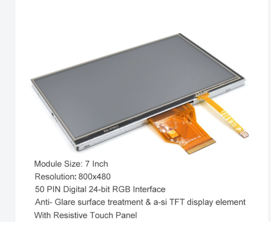
7-inch touch display module, model XRCGG070-0108-TPM-D1 — 1024 × RGB × 600, 700 cd/m², commonly used on compact HMI panels.
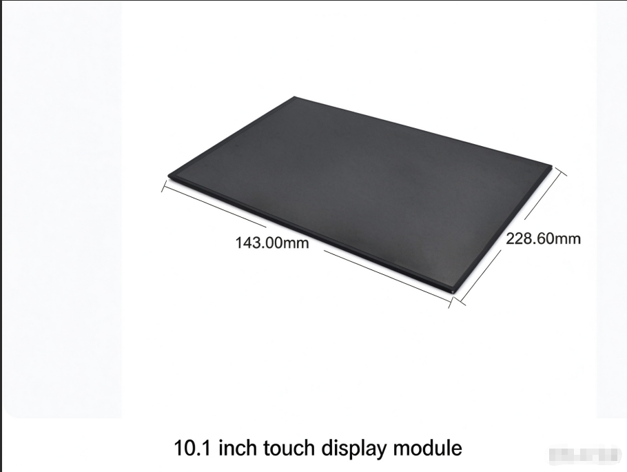
10.1-inch touch display module, model XRCGG101-0340-R1 — 1280 × RGB × 800, 800 cd/m², a common size for self-service and automation terminals.
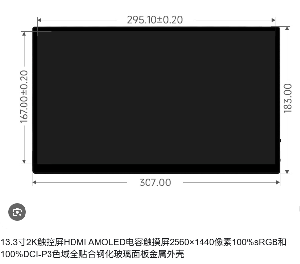
13.3-inch touch display module, model XRCGG133-0040-OB-A0 — 1920 × RGB × 1080, 1000 cd/m², wide-temperature operation.
| Model | Size | Resolution | Brightness | Operating Temp. |
|---|---|---|---|---|
| XRCGG070-0108-TPM-D1 | 7.0" | 1024 × 600 | 700 cd/m² | −20°C to +70°C |
| XRCGG101-0340-R1 | 10.1" | 1280 × 800 | 800 cd/m² | −20°C to +70°C |
| XRCGG133-0040-OB-A0 | 13.3" | 1920 × 1080 | 1000 cd/m² | −20°C to +70°C |
| XRCGG156-0186-A0 | 15.6" | 1920 × 1080 | 1000 cd/m² | −20°C to +70°C |
| XRCGG215-0106-A0 | 21.5" | 1920 × 1080 | 300 / 500 / 700 / 1000 cd/m² | −20°C to +70°C |
The 21.5-inch model deserves a note of its own because size drives structural cost. Its 16:9 active display area matches the cutouts of standard all-in-one enclosures and open frames, and a wide range of standard industry enclosure accessories is available for that format — which lowers the customer's structural development cost. Typical installations include all-in-one enclosures, open frames, self-service cabinets and medical trolleys.
Step-by-Step: How to Specify a Custom Touch Display Module
A specification can be built in seven steps. Each one closes a decision that is expensive to reopen later.
Step 1 — Describe the operating environment. Record ambient light level, temperature range, humidity, dust, cleaning agents, and whether the surface will be touched with bare hands, wet hands or gloves. This single paragraph determines brightness, surface treatment, sealing and touch tuning.
Step 2 — Select the touch technology. Choose capacitive where multi-point gestures, better display performance, a flush appearance and long service life matter. Choose 5-wire resistive where thick work gloves are mandatory, heavy oil contamination and splashing liquid are present, only single-point input is required, and the budget is constrained.
Step 3 — Fix the size and resolution against the enclosure. Work from the existing cutout and viewing distance. Standard sizes of 7, 10.1, 13.3, 15.6 and 21.5 inches cover most equipment formats, and matching a standard size usually avoids new tooling.
Step 4 — Choose the bonding method. Specify G+G full lamination with OCA where contrast, dust exclusion and anti-fog behaviour matter. Specify frame bonding where the environment is controlled and cost is the dominant constraint.
Step 5 — Choose surface treatment and touch options. Combine AF, AG and AR as the lighting and cleaning regime requires. Add thin-glove touch support and ESD protection where the application calls for them.
Step 6 — Confirm the electrical interface and operating system. Interfaces such as MIPI, LVDS and HDMI are available on the 21.5-inch model. Capacitive touch panels support Android, Linux and Windows; confirm the exact combination with the supplier before design freeze.
Step 7 — Validate the sample, then set the production schedule. Test the sample under the real ambient light, temperature and cleaning conditions described in Step 1. Only after that should quantities and delivery dates be fixed.
Use Cases by Industry
Industrial control equipment and automation. The HMI has to survive wide temperature swings, humidity, dust and 24/7 operation. The requirement set typically includes glove touch, strong resistance to drift, resistance to false triggering, consistent touch accuracy, IP68, IK10, ESD and EMC. Matched equipment includes industrial monitors, industrial HMIs and electrical cabinets.
New energy manufacturing. Charging piles and energy equipment combine wide temperature range, high humidity and dust with electromagnetic interference. Requirements usually include EMI/EMC, IP68, IK10, anti-condensation, resistance to damp-heat aging and high brightness.
Medical devices. Surfaces are disinfected repeatedly and may contact volatile or corrosive liquids. Relevant requirements include a coating resistant to repeated disinfection, a non-porous surface that does not encourage bacterial growth, high touch accuracy with stable coordinates, anti-misoperation behaviour, and EMC/ESD compliance.
Self-service intelligent equipment. Public terminals face wet hands, rain, dust and deliberate rough handling. Requirements centre on strong anti-mistouch behaviour, resistance to water-stain and rain interference, multi-state operation and touch-lock support.
Smart home devices. The priorities shift toward AF anti-fingerprint treatment, anti-mistouch, low power consumption, low blue light, flicker-free operation and full lamination for a flush, sealed front surface.
Comparison: Capacitive vs Resistive Touch Display Modules
The table below summarises the selection logic for both technologies as applied to industrial HMIs. It is a decision aid, not a ranking — each option is correct for a different set of conditions.
| Decision criterion | Capacitive touch display module | Resistive touch display module |
|---|---|---|
| Touch points | 10-point multi-touch with gesture support | Single-point operation |
| Glove and surface state | Bare hand, wet hand or thin glove | Heavy-duty work gloves, hard-object pressing |
| Environment | High-brightness workshop, outdoor strong light, long service life, flush IP protection | Heavy oil contamination, dust, splashing liquid |
| Display performance | Better optical performance with full lamination; flat appearance | Adequate for basic single-point interfaces |
| Budget position | Higher than resistive for equivalent size | Preferred where the budget is sensitive |
| 2025 global market share | 71% | 19% |
Market share figures: Business Research Insights, 2025. Selection characteristics: Xiangrui Optoelectronics application guidance for industrial control HMIs.
Working With a Custom Touch Display Module Manufacturer
Guangzhou Xiangrui Optoelectronics Technology Co., Ltd. is a touch screen and touch display module manufacturer based in Guangzhou, China, founded in 2010 and serving customers in Asia, Europe and America. The company develops, produces and customises touch screens and touch display modules; its main products are touch display modules, touch panels, touch screens and touch display cover glass, spanning both resistive and capacitive technologies.
Manufacturing capacity is documented as a 5,000 m² facility with 60 employees, including 15 engineers, and an annual production capacity of 300,000 units. The engineering team supports product customisation, technical evaluation, design optimisation and application-specific touch solutions — the work that sits between a requirement list and a production drawing. The company reports ISO 9001 and ISO 14001 certification, National High-Tech Enterprise status, and 16 utility model patents.
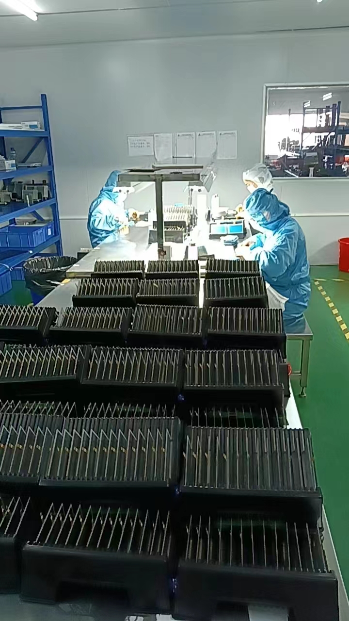
Final quality control (FQC) inspection on the production line, where finished touch display modules are checked before packing.
OEM and customised touch solutions are tailored to equipment designs, interface requirements and application environments. For buyers evaluating suppliers, three questions are worth asking early: which bonding method will be used and why, how the touch tuning will be validated against the real glove and moisture conditions, and what the actual lead time is for the specific configuration and order quantity. Lead times depend on product specifications and order quantities, so they should be confirmed per project rather than assumed from a general figure.
Frequently Asked Questions
What operating systems do the capacitive touch display modules support?
The capacitive touch panels support multiple operating systems, including Android, Linux and Windows. Because driver integration varies with the host board, the exact combination should be confirmed with the supplier before the design is frozen.
Is there a thickness limit for the cover glass of a touch screen?
Yes. The glass cover plate thickness can be customised, with a maximum thickness of 10 mm. Thicker cover glass is normally specified where the front surface faces deliberate impact or vandalism risk.
For an industrial control HMI, should I choose capacitive or resistive?
Where operators must wear heavy-duty work gloves or press with hard objects, where heavy oil contamination, dust and splashing liquid are present, where only single-point operation is needed and the budget is sensitive, a 5-wire resistive touch panel is preferred. Where multi-point gestures are needed, display performance matters, a flat appearance is required, operation is high-frequency, or the equipment sits outdoors in strong light, an industrial-grade projected capacitive touch screen is the better fit.
What are the protection and temperature ratings?
The documented touch display modules carry IP68 protection and IK10 impact resistance, with IP68 and IK10 stated as customisable on the 15.6-inch model. Operating temperature is −20°C to +70°C, with storage from −30°C to +80°C. IK10, as defined in IEC 62262, corresponds to withstanding 20 joules of impact energy.
How long does production take, and how do I start?
Lead time depends on product specifications and order quantities, so it is confirmed per project rather than quoted as a single figure. The usual starting point is a requirement list covering size, resolution, brightness, operating environment, bonding method and interface. Xiangrui Optoelectronics supports technical evaluation and design optimisation at that stage; a specification and quotation request can be sent to sales03@xiangruitec.com or +86 15975474413.
Conclusion
A custom touch display module is defined less by its size than by four decisions: which touch technology suits the operating conditions, which bonding method protects optical performance, which surface treatment matches the lighting and cleaning regime, and which environmental ratings are actually stated on the drawing. Capacitive technology is the mainstream choice at 71% of the 2025 market, but the remaining resistive share exists for good engineering reasons.
The practical next step for a buyer at the research stage is to write the environment down before requesting a price: ambient light, temperature, humidity, gloves, cleaning agents and enclosure cutout. That paragraph will do more to prevent a redesign than any comparison table.
Next step: request a specification or quotation
Send your size, brightness, operating environment and bonding requirement to the Xiangrui Optoelectronics engineering team, and request a matching sample for validation.
Email: sales03@xiangruitec.com | Phone / WhatsApp: +86 15975474413
Website: www.gzxrtp.com
Address: Room 402, Building A2, No.646, Xining West Road, Xintang Town, Zengcheng District, Guangzhou City, Guangdong Province, China
Download the company catalogue: Xiangrui Optoelectronics Catalogue (English)
Have Questions or Need More Details?
Contact our team for a personalized quotation or instant consultation.
Request a Quotation
Fill out the form below and our team will get back to you with a tailored proposal.
WhatsApp Direct Chat
Prefer to chat in real-time? Message us on WhatsApp for instant assistance & quick answers.
- Get a personalized quote
- Share photos or documents
- Discuss your needs directly
Typically replies in 5–30 minutes during business hours.