
Direct MV Grid Connection vs. AC-Coupled BESS: A Head-to-Head Decision Guide
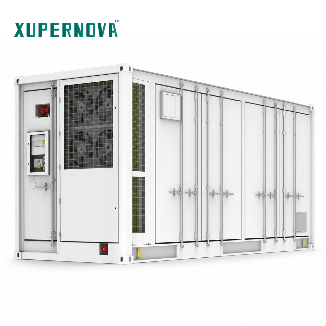
A battery energy storage system (BESS) reaches the grid through an AC-side architecture — and that architecture, more than cell chemistry, usually decides how long commissioning takes, how many maintenance points a site ends up carrying, and how cleanly a project grows from its first megawatt-hour to its tenth. This guide puts two approaches head to head: a directly medium-voltage (MV) connected, step-up-integrated BESS platform, and a conventional small-scale AC-coupled system that aggregates several low-voltage units before stepping up to the grid.
1. Problem Definition: The AC-Side Decision Most BESS Comparisons Skip
Most storage evaluations begin with chemistry, capacity and cycle life. Those parameters describe the DC side. What a buyer actually has to commission, protect, maintain and expand is the AC side — the power path from the power conversion system (PCS) output to the point of interconnection.
A complete storage plant is assembled from nine functional blocks: the battery system, the PCS, the battery management system (BMS), the plant-level energy management system (EMS), thermal management, fire protection, transformers, switchgear and the grid-connection system. Both architectures in this guide contain all nine blocks. The difference is how they are packaged and where the AC boundary sits.
- Direct MV connection with integrated step-up: transformer and MV switchgear scope is coordinated as part of the storage platform, and the platform presents a medium-voltage interface to the plant.
- Conventional AC-coupled: several low-voltage storage units, each with its own PCS, cooling loop and local controls, are paralleled on a low-voltage busbar and then stepped up by a separate transformer before reaching the grid.
That packaging choice cascades into conversion losses, cable runs, protection coordination, maintenance visits, spare-parts strategy and site works. It is the decision this guide is built around.
2. Industry Background: Why AC-Side Architecture Became a First-Order Question
Storage has moved from pilot scale to fleet scale. According to the IEA's Global Energy Review 2026, global new battery storage deployment reached 108 GW in 2025, and lithium iron phosphate (LFP) chemistry accounted for approximately 90% of those deployments. In the United States, the EIA's Preliminary Monthly Electric Generator Inventory projects utility-scale battery storage additions of 19.6 GW in 2025.
Three practical consequences follow for buyers in an evaluation-to-execution stage:
- Chemistry is converging. With LFP accounting for roughly nine of every ten deployed megawatt-hours, differentiation between suppliers has shifted from cell type to system integration — meaning the AC-side architecture and the controls that manage it carry more of the decision weight than they did five years ago.
- Equipment cost compression raises the value of execution. Ember reports that all-in CAPEX for long-duration (4-hour-plus) utility-scale BESS reached $125/kWh in late 2025, excluding China and the United States. When equipment cost per kWh compresses, site works, cabling, commissioning labor and O&M become a larger share of total project cost — exactly the cost categories that AC-side architecture controls.
- Procurement scope is expanding. Buyers increasingly compare scope boundaries (who supplies the transformer, who supplies the switchgear, who owns the grid-connection interface) rather than cells alone.
Market sizing should be read with care, because definitions differ. MarketsandMarkets estimates the global BESS market at $50.81 billion in 2025, while other research houses value a narrower, equipment-only scope considerably lower. That gap is a definitional one — turnkey system value chain versus battery equipment — and it is a reminder that the useful question is not the total market number but which part of the system a buyer is actually purchasing.
One further background point matters for containerized platforms entering the United States: BESS fully encased in housing is classified under US HTS 8507.60.00.90. Packaging is therefore visible in logistics and duty planning, not only in engineering.
3. Detailed Solution: The Two Architectures, Side by Side
3.1 Directly MV-Connected, Step-Up-Integrated Platform
In this architecture the storage platform is engineered to hand power to the plant at medium voltage. It builds on large-format containerized products such as the XA-V5015-L1, a 20-ft liquid-cooled battery container rated at 5.015 MWh with 0.5P/1P/2P capability and an operating range of −30 to 55 °C, or the XA-X2170-L2, a 20-ft liquid-cooled all-in-one container rated at 1125 kW / 2170.3 kWh (product reference 1129).
Four characteristics define the architecture:
- One AC interface. The platform's transformer and switchgear configuration is specified and supplied as part of the storage scope, rather than as a separate, later package with its own supplier and schedule.
- Integrated control hierarchy. PCS, BMS and plant-level EMS ship as one control stack, so protection, dispatch and monitoring share a single data model instead of being reconciled across vendors.
- Centralized thermal and fire systems. Liquid cooling and multi-layer fire protection are coordinated at platform level rather than repeated unit by unit.
- Fewer AC-side stages. Power leaves the PCS, is transformed at the platform, and arrives at the MV collection point. There is no intermediate low-voltage aggregation layer to design, cable, protect and maintain.
The mechanism behind lower system-level losses is structural. Fewer intermediate AC stages and shorter low-voltage runs between PCS output and the step-up transformer mean fewer places for conversion and conduction losses to accumulate, and one engineering owner for the entire AC path instead of a chain of interface handovers.
The maintenance consequence is equally structural. One platform plus one coordinated transformer and switchgear scope equals one maintenance regime, one spares category set and one control interface — instead of a distributed population of low-voltage units, each requiring inspection, firmware attention and cooling maintenance.
3.2 Conventional Small-Scale AC-Coupled Architecture
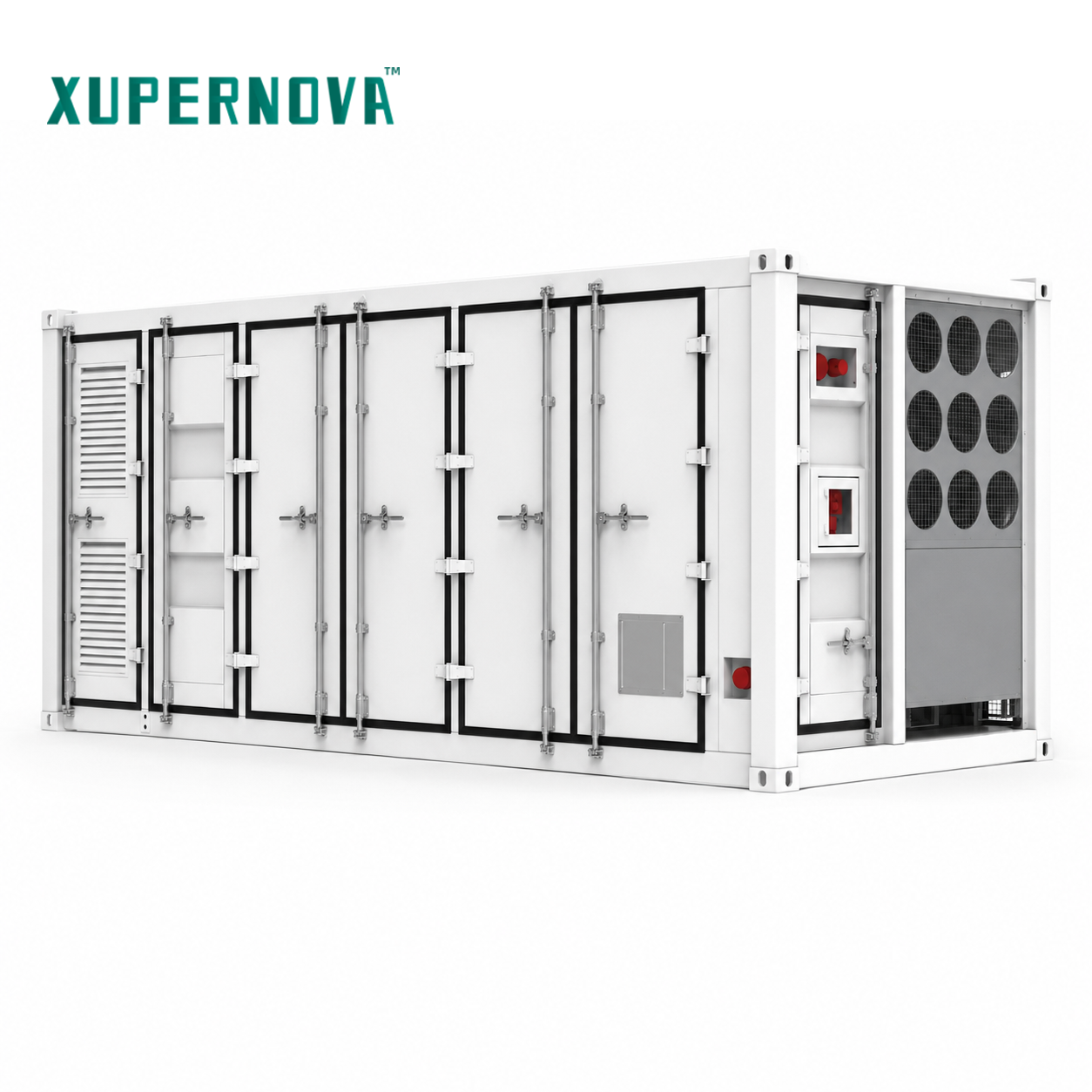
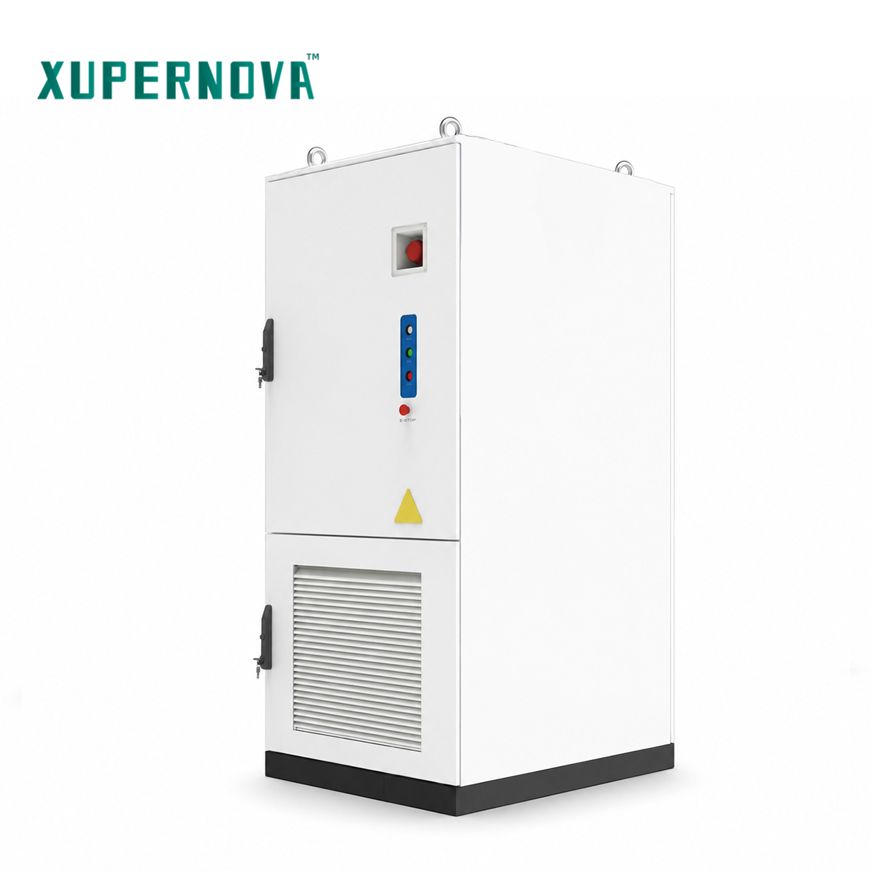
The AC-coupled approach uses several low-voltage units — for example the XA-C0261-L1, a liquid-cooled all-in-one cabinet rated at 125 kW / 261.25 kWh, or the XA-X1044-L1, a 10-ft liquid-cooled container rated at 500 kW / 1044 kWh — operating in parallel on a low-voltage busbar. A separate step-up transformer then raises voltage to the grid interface.
Where this architecture wins:
- Granularity and redundancy. Capacity is added in small increments, and the loss of one unit removes only a fraction of plant capacity.
- Multi-site replication. A standardized low-voltage cabinet can be repeated across many buildings under one procurement framework. One reference deployment used 50 units of 125 kW / 261.248 kWh at a supermarket and retail facility operator for peak shaving, time-of-use arbitrage and photovoltaic self-consumption, with remote monitoring and compatibility with Italian grid requirements, running stably for a year of daily operation.
- Lower entry per unit. The first investment is one cabinet, not a plant.
Where the trade-offs land:
- More AC interfaces. Every unit adds its own PCS output, protection and cabling to the low-voltage busbar.
- Distributed maintenance. Each unit carries its own cooling, controls and status signals; maintenance effort multiplies with unit and site count.
- Separate step-up scope. The transformer and MV switchgear are typically a separate package with its own supplier, schedule and interface risk.
- Higher on-site coordination load. Low-voltage collection, transformer, switchgear and grid connection must all be sequenced on site before energization.
3.3 How to Tell Which One Your Project Actually Needs
A simple decision rule works well at evaluation stage: count the interfaces, then count the sites.
- One interconnection, one owner, one expansion path, high power → a directly MV-connected, step-up-integrated platform.
- Many sites, small individual loads, incremental budget → AC-coupled cabinets aggregated at low voltage.
- Single site with a staged build-out → an early low-voltage phase is workable, provided the AC-side boundary for the later MV phase is agreed with the platform supplier before the interconnection application, because the protection and control boundary changes with it.
4. Step-by-Step Breakdown: Deployment and Lifecycle Checklist
The checklist below applies to either architecture. The further down the list you go, the more the two architectures diverge in effort and risk ownership.
Step 1 — Fix the point of interconnection and the voltage level. Confirm the utility's connection voltage, fault level and protection philosophy. Everything else in the AC-side design depends on this.
Step 2 — Choose the AC-side architecture before specifying equipment. Decide whether the plant will aggregate at low voltage and step up in a separate package, or whether the storage scope itself will present a medium-voltage interface.
Step 3 — Assign all nine functional blocks to an owner. Battery system, PCS, BMS, plant-level EMS, thermal management, fire protection, transformer, switchgear and grid-connection system.
Step 4 — Confirm grid-code and certification coverage at the AC boundary. For Italy, for example, Xupernova's energy storage system carries a CEI 0-21 compliance document issued by TÜV SÜD Product Service GmbH (certificate D 125581 0027 Rev. 00, standard CEI 0-21:2022/V2:2024, issued 22 September 2025) and a CEI 0-16 compliance document from the same authority (D 125581 0028 Rev. 00, standard CEI 0-16:2022/V3:2024). On the product side, the same system holds an IEC 63056:2020 product certificate (B 125581 0022 Rev. 01), an EMC attestation of conformity (E8A 125581 0023 Rev. 00) against EN IEC 61000-6-4:2019 and EN IEC 61000-6-2:2019, and an LVD attestation of conformity (N8A 125581 0024 Rev. 00) against EN 62477-1:2012/A12:2021.
Step 5 — Lock the protection and control interface. Communication protocols, the plant-level EMS boundary and the dispatch interface are all customization items. Decide them before factory acceptance testing, not during commissioning.
Step 6 — Validate at the factory, then on site. Require 100% FAT before shipment, including electrical safety testing, functional testing and aging testing, with third-party inspection available. Site acceptance testing is available to confirm the installed behaviour of the AC-side boundary.
Step 7 — Treat thermal and fire strategy as one system. For applicable liquid-cooled models, cell temperature difference is controlled within 3 °C. Detection combines smoke and temperature sensing; suppression is layered at PACK level and cluster level with an aerosol agent and a water fire-fighting interface, with multi-level temperature monitoring, BMS protection, automatic alarm and emergency shutdown.
Step 8 — Plan O&M before handover. Confirm the scope for 24/7 remote support, commissioning, training, diagnostics, spare parts and optional onsite service, and decide which of these sits with the platform supplier versus the EPC.
Step 9 — Fix the deployment and availability reference points contractually. For the MV-integrated platform path described in this guide, the reference points are an on-site deployment cycle up to 40% shorter and a system availability of at least 99.9%.
5. Use Cases: Where Each Architecture Pays Off
5.1 Grid-Side and Utility-Scale Renewable Integration
Projects with large-scale renewable fluctuation, grid congestion or dispatch obligations typically match the MV-integrated route. The matched equipment set for this class of project includes PCS, medium-voltage transformer, MV switchgear, AC collection system, substation equipment, protection and control, SCADA and plant-level EMS, with grid impact studies, local grid-code compliance, protection coordination and dispatch-interface requirements as standard constraints. One developer reference project used 2 MW / 4.176 MWh across seven units for renewable energy shifting, grid balancing and peak shaving, with an integrated PCS, BMS and EMS, liquid cooling, multi-source access and G99 grid-code compatibility.
5.2 Commercial and Industrial Peak Shaving and Time-of-Use Arbitrage
Where a single facility has high peak demand and time-of-use exposure, both architectures compete. A centralized choice is typical for larger loads: one industrial manufacturing reference project deployed 1 MW / 2.09 MWh across 20 units for peak shaving, time-of-use arbitrage and demand management, using an all-in-one liquid-cooled design, plant-level EMS, modular deployment, IP55 protection and compatibility with German grid requirements.
5.3 Solar-Plus-Storage
Where photovoltaic self-consumption and export limitation are the drivers, the storage scope must coordinate with PV inverters or hybrid PCS, combiner boxes, smart meters and, where backup is required, STS or EPS equipment.
5.4 Microgrids and Remote Industrial Sites
Weak-grid and off-grid sites — mining, remote industrial facilities — need grid-forming control, black-start capability and coordinated scheduling between PV, battery, diesel generators and loads. Where the site has a single, large point of interconnection, the MV-integrated platform reduces the number of parallel AC sources the microgrid controller must manage. One park operator deployed 1 MW / 2.088 MWh across 12 units for a solar-plus-storage microgrid with emergency backup and diesel optimization, using integrated STS, grid-connected and off-grid switching and centralized energy management, with improved continuity for critical loads over a seven-year operating period.
5.5 Critical Facilities
Hospitals, data centers and emergency services are driven by backup duration, islanding protection and black-start strategy rather than by capacity price. Both architectures are viable; the deciding factor is usually whether the critical-load distribution is centralized (favoring an MV-integrated plant) or spread across many buildings (favoring distributed cabinets).
5.6 Multi-Site Retail and Distributed Rollouts
For a retail chain or distributed estate, AC-coupled cabinets replicate the same design across dozens of sites without re-engineering the MV interface at each one. The 50-unit supermarket and retail deployment cited above is the clearest case for that pattern.
6. Comparison Table: MV-Integrated Platform vs. AC-Coupled BESS
| Decision Dimension | Directly MV-Connected, Step-Up-Integrated Platform | Conventional Small-Scale AC-Coupled BESS |
|---|---|---|
| Grid interface presented by the storage scope | Medium-voltage interface; transformer and MV switchgear configuration coordinated within the platform scope | Low-voltage busbar aggregation; separate step-up transformer and switchgear package |
| AC-side stages from PCS output to grid | Fewer intermediate stages; step-up performed at the platform | Multiple parallel low-voltage interfaces plus a separate transformer stage |
| Reference products in the Xupernova range | XA-V5015-L1 (5.015 MWh, 20-ft liquid-cooled battery container); XA-X2170-L2 (1125 kW / 2170.3 kWh) | XA-C0261-L1 (125 kW / 261.25 kWh all-in-one cabinet); XA-X1044-L1 (500 kW / 1044 kWh, 10-ft container) |
| Maintenance model | Centralized: one platform, one control hierarchy, one spares strategy | Distributed: each unit has its own PCS, cooling and controls |
| On-site coordination | Single AC boundary to sequence with the utility and the EPC | Low-voltage collection, transformer, switchgear and grid connection sequenced as separate packages |
| Expansion pattern | Add platforms at the same MV collection point | Add cabinets unit by unit at low voltage |
| Best-fit scale and topology | One interconnection point, high power, grid-side or large commercial and industrial | Many sites, small individual loads, staged or incremental budgets |
| Thermal and fire scope | Coordinated at platform level; liquid cooling controls cell temperature difference within 3 °C for applicable models, with layered PACK-level and cluster-level suppression | Repeated per unit, with each cabinet carrying its own cooling and detection |
| Deployment and availability reference points | On-site deployment cycle up to 40% shorter; system availability of at least 99.9% | Driven by unit count and site sequencing, not by a single platform reference point |
| Typical status during evaluation | Chosen when the AC-side boundary is part of the supplier's scope | Chosen when site count, not plant power, is the dominant variable |
7. Frequently Asked Questions
Which certifications and grid-code documents should a buyer verify for a directly MV-connected BESS?
Verify both product-level safety and EMC certificates and the local grid-code compliance documents at the AC boundary. Xupernova's energy storage system holds an IEC 63056:2020 product certificate (B 125581 0022 Rev. 01) covering a DC 832 V, 314 Ah rechargeable lithium-ion battery system, an EMC attestation of conformity (E8A 125581 0023 Rev. 00) against EN IEC 61000-6-4:2019 and EN IEC 61000-6-2:2019, and an LVD attestation of conformity (N8A 125581 0024 Rev. 00) against EN 62477-1:2012/A12:2021, all issued by TÜV SÜD Product Service GmbH. For Italy, the CEI 0-21 and CEI 0-16 compliance documents (D 125581 0027 Rev. 00 and D 125581 0028 Rev. 00) define the grid-connection rules for the energy storage system model ECO-E261LP-2A.
What can be customized in an OEM or ODM commercial battery energy storage system?
OEM and ODM services are available. Customization covers system power and energy capacity; charge/discharge duration; AC/DC voltage; battery chemistry and cell supplier; PCS, BMS and plant-level EMS; photovoltaic input and solar-plus-storage configuration; on-grid/off-grid operation; STS/EPS backup function; cooling system; fire protection system; enclosure size, color and branding; IP rating and corrosion protection; grid code; and communication protocols, transformer and switchgear configuration.
How should commercial terms be compared between an MV-integrated platform and AC-coupled cabinets?
Compare the scope boundary, not the headline unit price. In Xupernova's standard terms the MOQ is 1 unit, delivery terms are EXW / FOB / CIF / DAP / DDP, and payment is 30% deposit with 70% before shipment after FAT. Where an MV-integrated platform includes transformer and switchgear configuration inside the storage scope, that scope should be compared against the combined cost of cabinets, low-voltage collection equipment, a separate step-up transformer and switchgear, and the site labor required to coordinate them.
Can a single unit be validated before full deployment?
Yes. With an MOQ of 1 unit, a single platform or cabinet can be used to validate the design before wider rollout. Every unit passes 100% FAT, electrical safety testing, functional testing and aging testing before shipment, and third-party inspection and site acceptance testing (SAT) are available.
What is the lead time for an OEM battery energy storage system order?
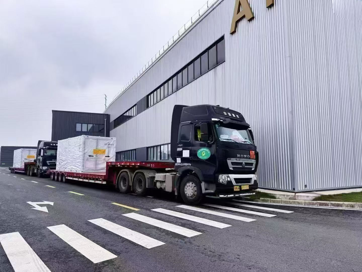
Lead time is 25–35 days for standard BESS and 35–60 days for customized projects, supported by monthly capacity of up to 500 MWh/month. To start a project review, download the Xupernova Energy Storage Product Catalog or send your voltage level, required capacity and target energization date to bill@xupernovatech.com / +86 186-0828-3917 and the team will return a scoped configuration review.
8. Conclusion: Decide the AC Boundary First, Then the Equipment
The head-to-head between a directly MV-connected, step-up-integrated platform and a conventional AC-coupled BESS is not a contest between two product families. It is a choice about where the AC boundary sits, who owns it, and how many interfaces the site will carry for the next ten to fifteen years.
For a single high-power interconnection with one operating team, the MV-integrated route reduces AC-side stages, concentrates maintenance into one regime, and gives the project one owner for the transformer, switchgear and grid-connection scope — with reference points of an on-site deployment cycle up to 40% shorter and system availability of at least 99.9%. For a distributed estate or an incremental budget, AC-coupled cabinets remain the more flexible instrument, provided the future MV boundary is planned before the interconnection application rather than after.
Whichever route a project takes, the same nine blocks must be coordinated end to end: battery system, PCS, BMS, plant-level EMS, thermal management, fire protection, transformer, switchgear and grid-connection system. Xupernova New Energy Technology Co., Ltd. (Xupernova), founded in 2015, manufactures energy storage systems at a 700,000 m² facility with 5 GWh+ annual capacity, 150+ R&D engineers and a 90% export ratio across Europe, North America, South America, the Middle East and Asia, and supplies both containerized MV-class platforms and distributed all-in-one cabinets under standard, OEM and ODM models.
Next Step
Send your single-line diagram, required capacity and target connection voltage for a scoped comparison of an MV-integrated platform against an AC-coupled layout — including the transformer, switchgear and grid-connection scope that each option carries.
- Email: bill@xupernovatech.com (Bill Liao)
- Tel / WhatsApp: +86 186-0828-3917
- Catalog download: XUPERNOVA Energy Storage Product Catalog (PDF)
- Website: www.xupernovatech.com | Blog: blog.xupernovatech.com
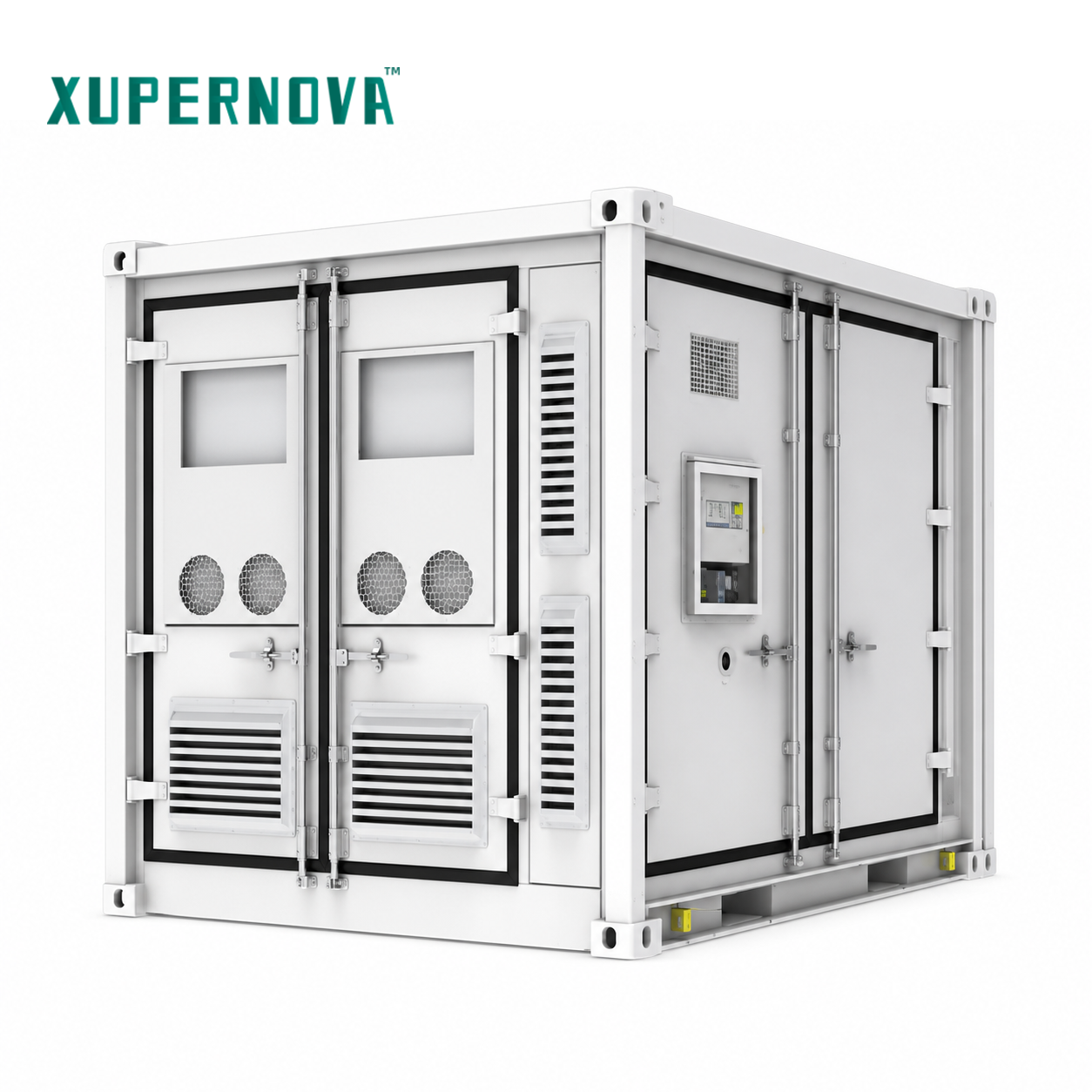
Product specifications referenced in this guide: XA-V5015-L1 (5.015 MWh, 20-ft liquid-cooled battery container, 0.5P/1P/2P); XA-X2170-L2 (1125 kW / 2170.3 kWh, 20-ft liquid-cooled all-in-one container); XA-X1044-L1 (500 kW / 1044 kWh, 10-ft liquid-cooled container); XA-C0261-L1 (125 kW / 261.25 kWh, liquid-cooled all-in-one cabinet); XA-H0261-L1 (261 kWh liquid-cooled solar-plus-storage cabinet); XA-H0064-A1 (25–50 kW / 64.54 kWh air-cooled solar-plus-storage cabinet). All listed systems operate across a −30 to 55 °C scope and use Grade A LFP lithium-ion cells from leading BloombergNEF Tier 1 energy-storage cell manufacturers, with optional semi-solid-state, solid-state and sodium-ion technologies subject to project requirements, technical validation and availability.
Have Questions or Need More Details?
Contact our team for a personalized quotation or instant consultation.
Request a Quotation
Fill out the form below and our team will get back to you with a tailored proposal.
WhatsApp Direct Chat
Prefer to chat in real-time? Message us on WhatsApp for instant assistance & quick answers.
- Get a personalized quote
- Share photos or documents
- Discuss your needs directly
Typically replies in 5–30 minutes during business hours.