
Medium-Voltage BESS Integration and Step-Up Selection Parameters: A Technical Guide
Medium-voltage (MV) integration is the AC-side decision that determines how much of a battery energy storage system (BESS) arrives as a factory-built unit and how much is engineered on site. Two questions drive it: at which point does the storage system connect to the project's MV network, and who owns the step-up transformer and MV switchgear that make that connection possible?
The short answer is that direct MV connection and integrated step-up are selection parameters, not fixed catalogue attributes. In Xupernova's OEM/ODM configuration scope, transformer and switchgear configuration is listed alongside AC/DC voltage, PCS, BMS and plant-level EMS, grid code and communication protocols. Two quotations describing the same megawatt-hour figure can therefore describe two very different scopes of supply, and comparing them without normalising the AC side is one of the most common early-stage errors in large BESS procurement.
Working definitions used in this guide
- Direct MV connection — the storage system's AC interface is designed to sit at the project's medium-voltage level, so the step-up function and MV switchgear are treated as part of the storage scope rather than as separately procured plant equipment.
- Integrated step-up — the step-up function is specified together with the PCS, protection and control package as one engineering package, instead of being tendered as an independent item.
- LV AC-coupled cluster — each storage unit delivers low-voltage AC and the plant steps up once through a project transformer owned outside the storage supply scope.
Problem Definition: Where LV-Only AC Coupling Stops Scaling
Low-voltage AC coupling works well until a project outgrows it. As capacity grows, three costs grow with it: the number of parallel AC interfaces, the number of protection and metering points that must be coordinated, and the volume of site work — cabling, terminations, low-voltage distribution and commissioning steps — that sits between the units and the transformer.
Parameter drift makes this worse. If individual units differ in C-rate, cooling type, EMS version or communication protocol, the plant-level controller has to reconcile them. Xupernova's container and cabinet platforms support 0.5P, 1P and 2P C-rates and share a common cell basis — Grade A LFP lithium-ion cells from BloombergNEF Tier 1 energy-storage cell manufacturers — but the plant still has to be designed as one system rather than as a collection of independently specified machines.
Grid-code and protection requirements then land at plant level. For utility-scale renewable integration and grid-side energy storage, the equipment set includes the PCS, a medium-voltage transformer, MV switchgear, the AC collection system, substation equipment, a protection and control system, SCADA and plant-level EMS. The associated project requirements include a grid impact study, local grid-code compliance, protection coordination, dispatch-interface requirements, cybersecurity, fire safety and environmental assessment.
The practical consequence is that the location of the storage system's AC boundary — DC bus, low-voltage AC terminals, or the MV interface — changes the scope of every one of those items. That boundary is the parameter that should be settled first, before power, energy or container count.
Industry Background: DC-Side Standardisation Has Moved Engineering Risk to the AC Side
Two figures frame the current design conversation. According to the IEA's Global Energy Review 2026, global new battery storage deployment reached 108 GW in 2025, and LFP chemistry accounted for approximately 90% of global battery storage deployments in that year. A single dominant chemistry and a limited number of container form factors mean that the DC-side building block of a utility-scale project is now relatively standardised across suppliers.
Cost benchmarks reinforce this. Ember reports all-in BESS project CAPEX for long-duration (4-hour plus) utility-scale projects at $125/kWh in late 2025 for markets outside China and the United States. When the battery block itself is increasingly commoditised and its headline cost is falling, the differentiation between competing offers concentrates in what surrounds it: the AC-side architecture, the protection and control scope, the site works, and the service model.
Market sizing should be read with care. MarketsandMarkets estimates the global BESS market at $50.81 billion in 2025, but published valuations diverge sharply — other research houses value the same year far lower because they exclude PCS, EMS and civil scope from the definition. That divergence is itself a useful procurement signal: whenever a cost or market figure is used to justify an AC-side scope decision, the system boundary behind the number should be checked first.
Two further constraints apply to large projects. In the United States, a BESS fully encased in housing is classified under HTS 8507.60.00.90, which affects how a delivered system — as opposed to separately shipped cells, modules or PCS — is declared. And in the United States specifically, utility-scale battery storage capacity growth was projected to reach 19.6 GW in 2025 according to the U.S. Energy Information Administration's Preliminary Monthly Electric Generator Inventory, indicating that most new capacity is being added at a scale where MV interconnection is the default rather than the exception.
Detailed Solution: A Configurable Container Platform with an AC-Side Scope
Xupernova New Energy Technology Co., Ltd. (Xupernova) is an energy storage and new energy solutions provider founded in 2015, operating a 700,000 m² manufacturing base with more than 500 employees and more than 150 R&D engineers, an annual capacity of 5 GWh+ and a monthly output of up to 500 MWh. Approximately 90% of output is exported to Europe, North America, South America, the Middle East and Asia (www.xupernovatech.com).
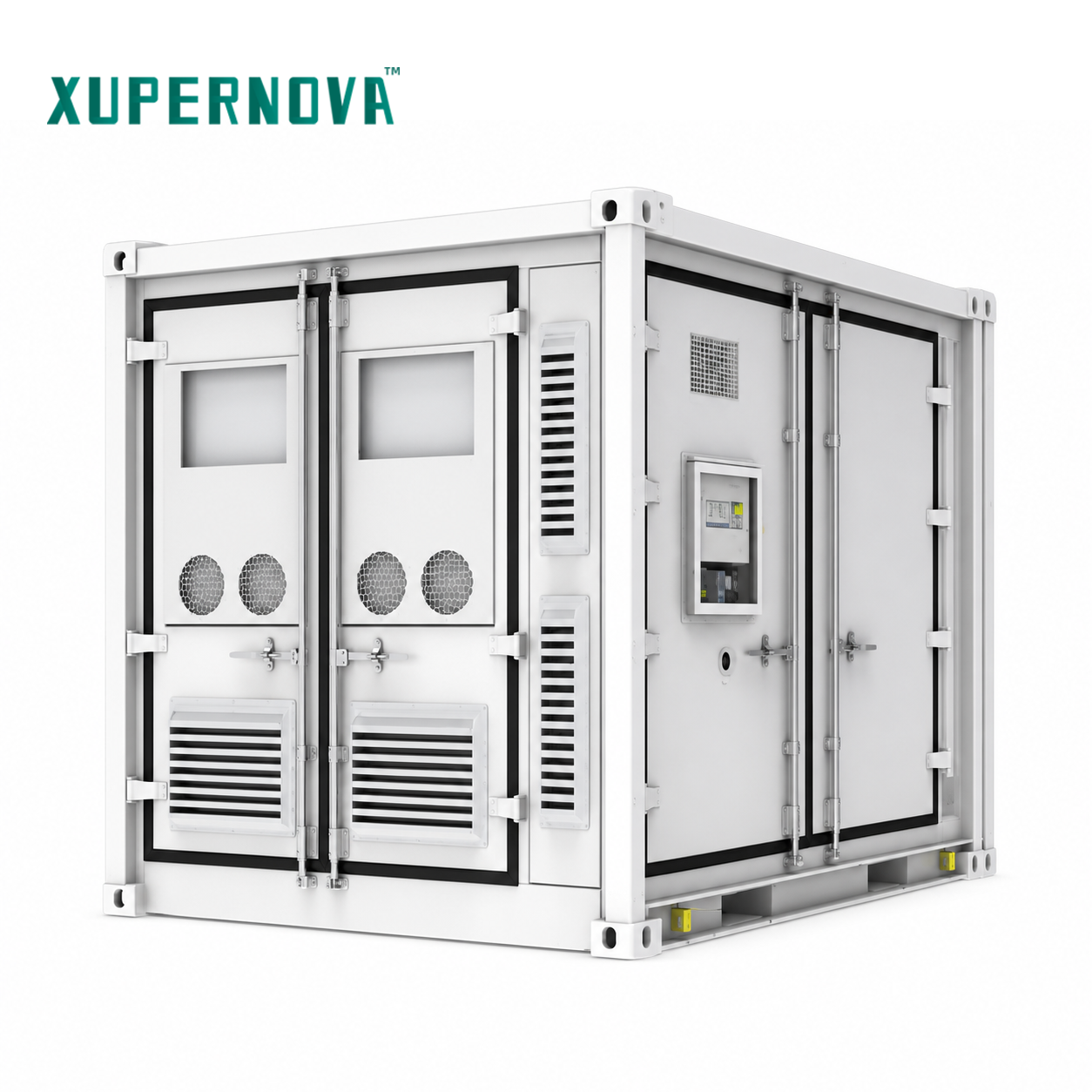
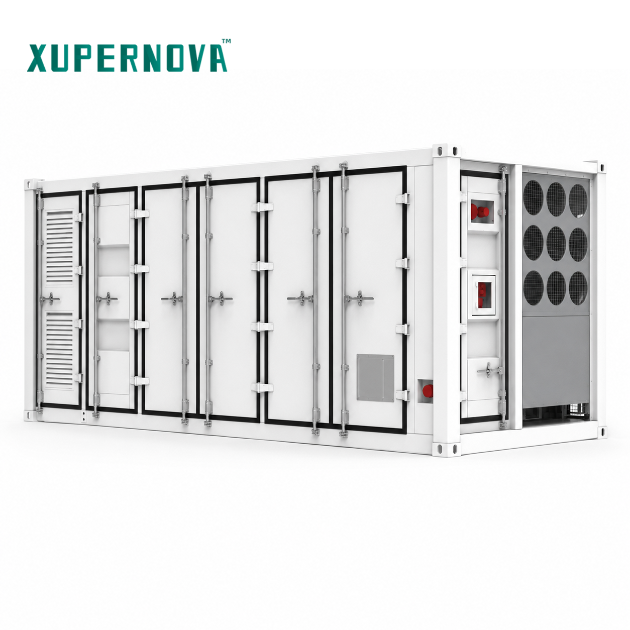
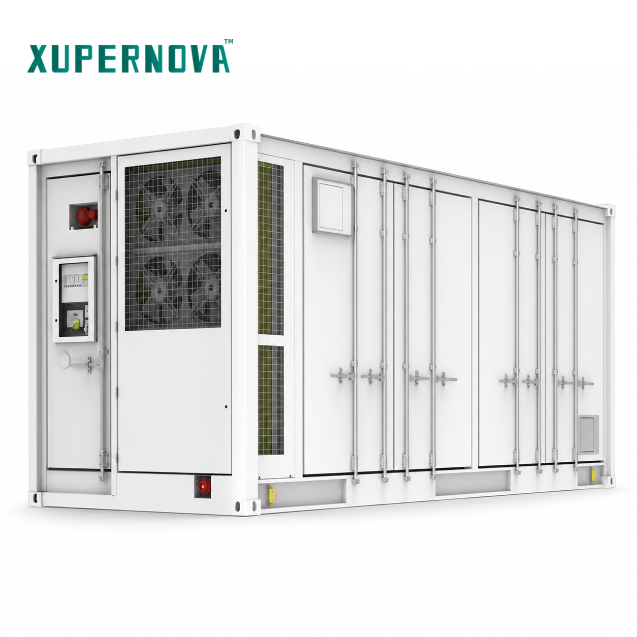
For MV-scale work, the relevant part of the portfolio is the container and cabinet line. The XA-V5015-L1 is a 20-ft liquid-cooled battery container with a rated energy capacity of 5.015 MWh, designed for power generation, grid energy storage and commercial and industrial applications. The XA-X2170-L2 is a 20-ft liquid-cooled all-in-one ESS container rated 1125 kW / 2170.3 kWh for commercial and industrial and grid-side energy storage. The XA-X1044-L1 is a 10-ft liquid-cooled all-in-one ESS container rated 500 kW / 1044 kWh, applied in commercial and industrial storage, microgrids and backup power. At the smaller end, the XA-C0261-L1 is a liquid-cooled all-in-one ESS cabinet rated 125 kW / 261.25 kWh, and the solar-plus-storage line adds the liquid-cooled XA-H0261-L1 at 261 kWh and the air-cooled XA-H0064-A1 at 25–50 kW / 64.54 kWh.
Every model in this line shares the same engineering base: Grade A LFP lithium-ion cells from BloombergNEF Tier 1 manufacturers, optional semi-solid-state, solid-state and sodium-ion battery technologies subject to project requirements, technical validation and availability, an IP55 protection level, an operating range of -30°C to 55°C, and support for 0.5P, 1P and 2P C-rates.
The parameter that matters most for MV integration sits in the configuration scope rather than the data sheet. Xupernova's OEM/ODM customisation fields cover system power and energy capacity; charge/discharge duration; AC/DC voltage; battery chemistry and cell supplier; PCS, BMS and plant-level EMS; photovoltaic input and solar-plus-storage configuration; on-grid/off-grid operation; STS/EPS backup function; cooling system; fire protection system; enclosure size, colour and branding; IP rating and corrosion protection; grid code; communication protocols; and transformer and switchgear configuration.
Because the AC-side boundary is configurable, the correct engineering sequence is to define it before pricing rather than after. A project that assumes the quoted container stops at its low-voltage AC terminals and a project that assumes the same container is quoted with the step-up function inside the scope are not buying the same product, even when the MWh figure and the cell specification are identical.
Step-by-Step Breakdown: Parameters to Fix Before a Quotation Is Comparable
Step 1 — Fix the grid interface point and the voltage level defined by local code
Start with the interconnection point and the voltage level that the local grid code assigns to it. The MV level itself is a project and jurisdiction parameter; it must not be inferred from a supplier catalogue. Once the interface point is fixed, the question of whether the step-up sits inside or outside the storage scope becomes answerable.
Step 2 — Convert the duty cycle into a power-to-energy ratio
Define required power (kW or MW) and required energy (kWh or MWh), then express them as a C-rate. Xupernova's container and cabinet platforms support 0.5P, 1P and 2P. A 0.5P duty suits longer-duration shifting, 1P suits mainstream peak shaving and load shifting, and 2P suits higher-power applications. The C-rate choice drives cell configuration, cooling load and AC-side sizing simultaneously.
Step 3 — Select the AC-side archetype
Choose between a low-voltage AC-coupled cluster and an MV-connected arrangement in which the step-up function is specified with the storage system. The decision is driven by project size, whether MV distribution already exists on site, and whether the owner wants one interface or several.
Step 4 — Specify the AC-side equipment set as one package
For utility-scale grid-side storage, the equipment set to be specified includes the PCS, medium-voltage transformer, MV switchgear, AC collection system, substation equipment, protection and control system, SCADA, plant-level EMS and the communication system. Transformer and switchgear configuration is an available configuration field in Xupernova's customisation scope, which allows the AC chain to be defined together with the PCS and EMS rather than tendered separately.
Step 5 — Evaluate conversion stages, losses and balance-of-system cost
Every additional conversion and voltage-transformation stage between the battery terminals and the MV grid interface adds losses and equipment. In an LV AC-coupled cluster, the energy passes through each unit's power conversion stage and then through the project step-up transformer. Where the step-up and MV switchgear are specified inside the storage scope, the AC chain is designed as a single package, which generally allows the number of interfaces, the length of low-voltage AC runs and the associated balance-of-system items to be resolved on the drawing board rather than on site. This is a design-logic statement, not a measured efficiency claim; the actual loss and cost outcome depends on the specific layout and duty cycle.
Step 6 — Map the certification and grid-code evidence
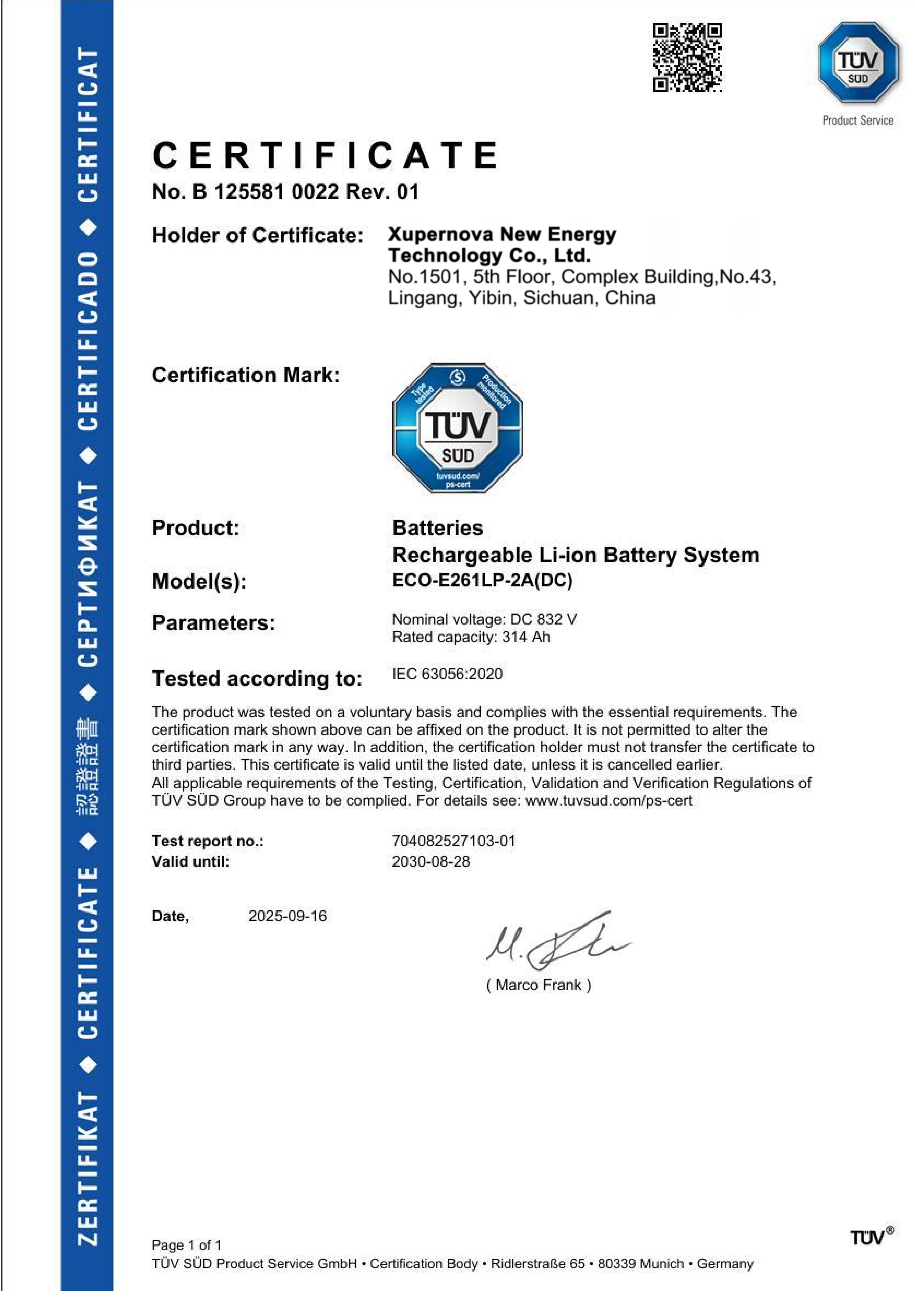
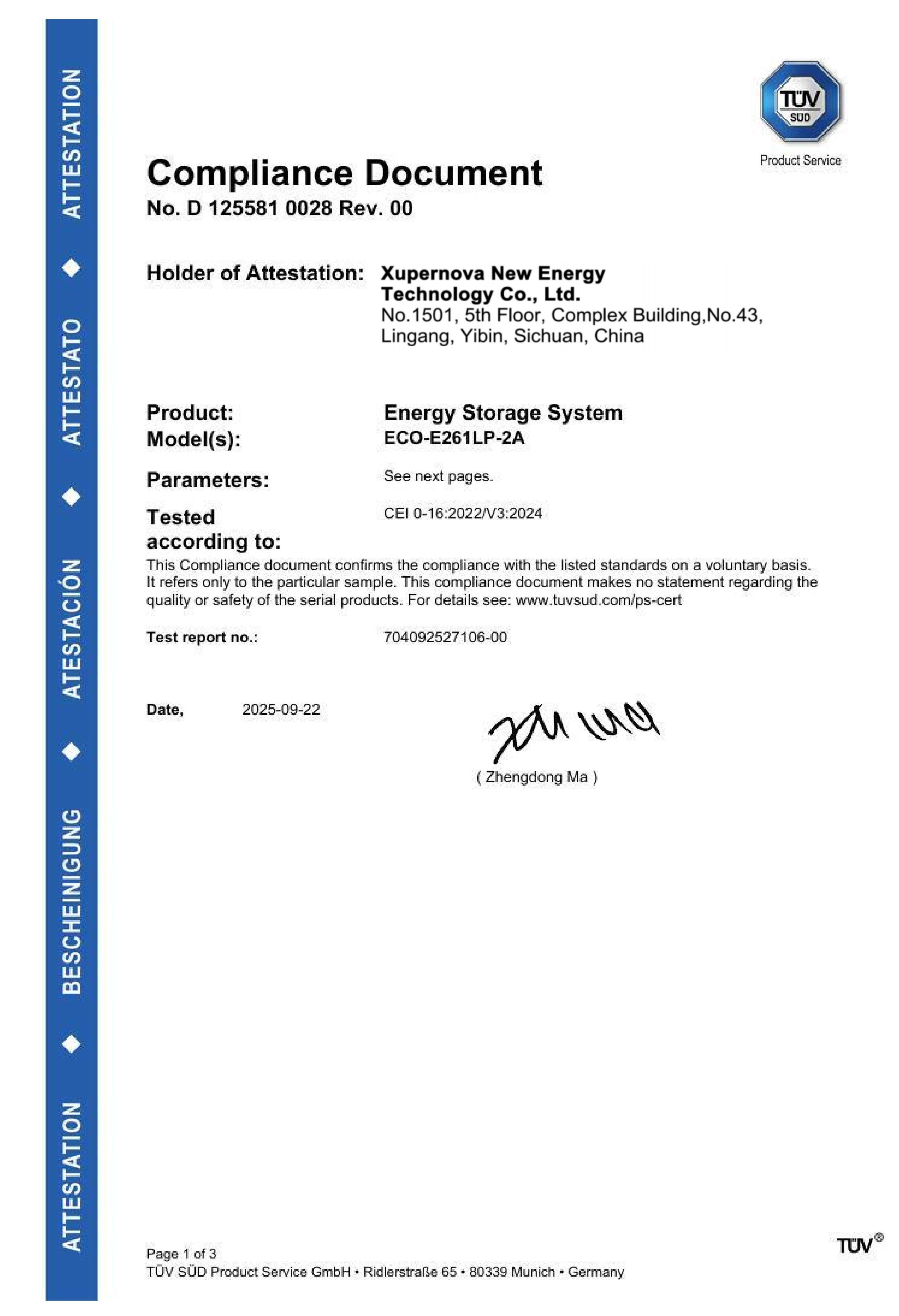
Certification evidence should be assembled at the same time as the technical scope, because it constrains both the model selection and the market. Xupernova's Battery Energy Storage System product holds an IEC 63056:2020 product certificate, number B 125581 0022 Rev. 01, issued by TÜV SÜD Product Service GmbH for the global market. For the European Union, the ECO-E261LP-2A Energy Storage System (125 kW, 261.248 kWh, IP55) is covered by an LVD Attestation of Conformity to EN 62477-1:2012/A12:2021, number N8A 125581 0024 Rev. 00, and by an EMC Attestation of Conformity to EN IEC 61000-6-4:2019 and EN IEC 61000-6-2:2019, number E8A 125581 0023 Rev. 00. For Italy, the same model is certified to CEI 0-21:2022/V2:2024, number D 125581 0027 Rev. 00, and to CEI 0-16:2022/V3:2024, number D 125581 0028 Rev. 00.
Step 7 — Plan site works and the maintenance model
The site-works and service consequences of the chosen architecture should be priced explicitly. A cluster of small units distributes access and service points across the site; a containerised MV-connected arrangement concentrates commissioning, monitoring and service access at container level, supported by plant-level EMS and remote monitoring. In practice, the maintenance model — how many points of access, how far technicians travel, and whether faults are diagnosed remotely or on site — is a cost line that should be compared alongside the equipment price.
Step 8 — Set validation, lead time and commercial parameters
Factory validation for the platform includes 100% FAT, electrical safety testing, functional testing, aging testing, and third-party inspection on request. Minimum order quantity is 1 unit. Lead time is 25–35 days for standard BESS and 35–60 days for customised projects, against a monthly capacity of up to 500 MWh. Customised MV-side scope sits at the longer end of that range, so the AC-side definition should be frozen early if the project schedule is fixed.
Use Cases: Which Projects Actually Need MV Integration
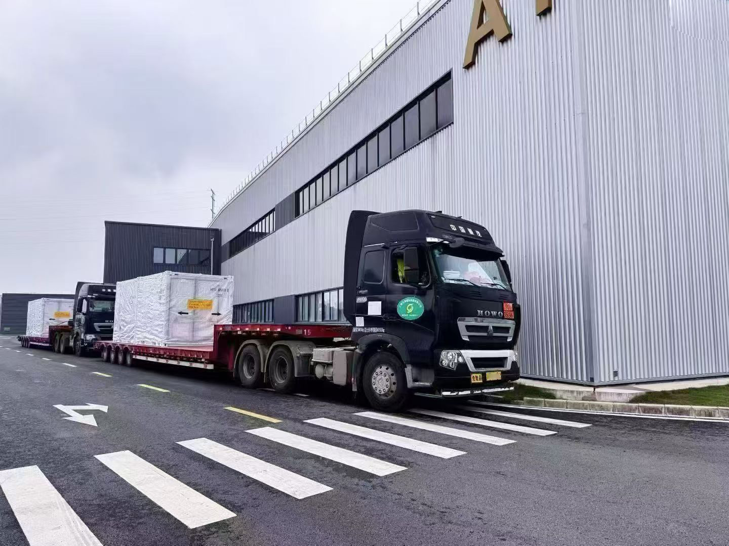
The MV interface is not automatically the right answer for every project. It becomes the dominant consideration where the storage system connects to a medium-voltage distribution network or a substation rather than to a low-voltage building supply.
- Utility-scale renewable integration and grid-side storage. Large renewable fluctuations, grid congestion, curtailment and dispatch obligations call for renewable energy shifting, peak regulation, frequency support, power smoothing and dispatchable capacity, controlled through centralised plant-level EMS responding to grid dispatch commands, market signals and generation forecasts.
- Remote mining and off-grid microgrids. Weak-grid or off-grid sites with high diesel consumption and large motor-starting loads require grid-forming control, coordinated scheduling of solar, battery and diesel generation, black-start capability and remote O&M.
- Commercial and industrial peak shaving. Facilities on time-of-use tariffs use 24/7 automatic charge/discharge scheduling, load-following and demand-limit control to reduce maximum demand and demand charges.
- Critical-load backup. Hospitals, data centres and emergency services require islanded backup operation, which in practice is configured with grid-forming PCS and an STS or EPS cabinet.
- Solar-plus-storage and microgrids. Intermittent photovoltaic generation with daytime surplus and evening peaks benefits from PV, battery, load and grid coordination with export limitation and grid-code compliance.
- EV charging hubs and fleet depots. Concentrated charging periods with limited grid capacity are addressed by coordinating grid power, PV, storage and charging loads, which can defer transformer upgrades.
Delivered reference cases show the range of what has been built. A renewable energy project developer deployed 2 MW / 4.176 MWh across seven units for renewable shifting, grid balancing, peak shaving and backup power, with a compact 10-ft container design, integrated PCS/BMS/EMS, liquid cooling, multi-source access and G99 grid-code compatibility. A commercial and industrial park operator deployed 1 MW / 2.088 MWh across twelve units for a solar-plus-storage microgrid with emergency backup and diesel optimisation, using integrated STS and grid-connected/off-grid switching with centralised energy management. An industrial manufacturing enterprise deployed 1 MW / 2.09 MWh across twenty units for peak shaving, time-of-use arbitrage and demand management, with plant-level EMS and compatibility with German grid requirements.
Smaller sites follow the same logic at a different scale. A supermarket and retail facility operator deployed 125 kW / 261.248 kWh units — fifty in total — for peak shaving, time-of-use arbitrage and photovoltaic self-consumption over one year, using a compact all-in-one liquid-cooled design with low on-site installation workload, remote monitoring and compatibility with Italian grid requirements. A commercial facility and solar EPC contractor deployed 500 kW / 1.044 MWh units with up to 1 MW PV input across thirty-two units for self-consumption, peak shaving, arbitrage and emergency power support, using a liquid-cooled solar-plus-storage design with wide PV input range, modular expansion and plant-level EMS.
Comparison: MV-Connected Scope Versus Conventional LV AC-Coupled Clusters
The table below sets out the design-logic differences between the two AC-side archetypes. It is a selection framework rather than a measured performance comparison; the actual outcome depends on project layout, duty cycle and local grid code.
| Selection parameter | LV AC-coupled cluster (multiple small units) | MV-connected system with step-up in scope |
|---|---|---|
| Position of the step-up function | Project transformer, usually outside the storage supply scope | Transformer and switchgear configuration can be included as a storage configuration field |
| AC conversion chain | Each unit converts DC to low-voltage AC, then the plant steps up once | AC output specified together with the step-up function, MV switchgear, protection and control |
| AC collection and equipment set | Collection grows with the number of parallel unit interfaces | PCS, MV transformer, MV switchgear, AC collection, substation equipment, protection and control, SCADA and plant EMS specified as one set |
| Protection and grid-code work | Coordinated across many low-voltage interfaces plus the plant transformer | Handled as plant-level requirements: grid impact study, grid-code compliance, protection coordination, dispatch interface |
| Site works | Cabling, terminations and low-voltage distribution scale with unit count | Generally concentrates at the MV interface, foundations, container placement and commissioning |
| Maintenance and monitoring | Distributed service access across many units | Container-level access with plant-level EMS, remote monitoring and 24/7 remote support options |
| Typical fit | Smaller C&I sites where low-voltage infrastructure already exists | Grid-side, utility-scale and large industrial loads already operating at medium voltage |
Framework summarising design logic; not a measured performance or cost comparison.
Regardless of archetype, the underlying hardware options for a large project are the same container and cabinet platforms. The table below lists the current Xupernova models with their published specifications.
| Model | Type | Rated power / energy | Cooling | Protection & temperature | Applicable use |
|---|---|---|---|---|---|
| XA-V5015-L1 | 20-ft liquid-cooled battery container | 5.015 MWh (0.5P/1P/2P; power rating configured per project) | Liquid | IP55, -30°C to 55°C | Power generation, grid energy storage, C&I |
| XA-X2170-L2 | 20-ft liquid-cooled all-in-one ESS container | 1125 kW / 2170.3 kWh (0.5P/1P/2P) | Liquid | IP55, -30°C to 55°C | C&I, grid-side energy storage |
| XA-X1044-L1 | 10-ft liquid-cooled all-in-one ESS container | 500 kW / 1044 kWh (0.5P/1P/2P) | Liquid | IP55, -30°C to 55°C | C&I, microgrids, backup power |
| XA-C0261-L1 | Liquid-cooled all-in-one ESS cabinet | 125 kW / 261.25 kWh (0.5P/1P/2P) | Liquid | IP55, -30°C to 55°C | C&I energy storage |
| XA-H0261-L1 | Liquid-cooled solar-plus-storage cabinet | 261 kWh (0.5P/1P/2P) | Liquid | IP55, -30°C to 55°C | C&I solar-plus-storage, microgrids |
| XA-H0064-A1 | Air-cooled solar-plus-storage cabinet | 25–50 kW / 64.54 kWh (0.5P/1P/2P) | Air | IP55, -30°C to 55°C | Small-scale C&I solar-plus-storage |
All models use Grade A LFP lithium-ion cells from BloombergNEF Tier 1 energy-storage cell manufacturers, with optional semi-solid-state, solid-state and sodium-ion battery technologies subject to project requirements, technical validation and availability.
FAQ
Which certifications and standards should be verified first on a medium-voltage BESS project?
Three evidence groups matter, in this order. First, cell and battery-system safety: the Xupernova Battery Energy Storage System product holds an IEC 63056:2020 product certificate, number B 125581 0022 Rev. 01, issued by TÜV SÜD Product Service GmbH for the global market. Second, grid-connection compliance for the destination market: the ECO-E261LP-2A Energy Storage System is certified to Italy's CEI 0-21:2022/V2:2024 under certificate D 125581 0027 Rev. 00 and to CEI 0-16:2022/V3:2024 under certificate D 125581 0028 Rev. 00, both issued by TÜV SÜD Product Service GmbH. Third, EU electrical safety and electromagnetic compatibility: the same model carries an LVD Attestation of Conformity to EN 62477-1:2012/A12:2021 (N8A 125581 0024 Rev. 00) and an EMC Attestation of Conformity to EN IEC 61000-6-4:2019 and EN IEC 61000-6-2:2019 (E8A 125581 0023 Rev. 00). Project-level requirements — grid impact study, protection coordination, dispatch interface, cybersecurity and fire safety — sit on top of these and are assessed per site.
Can the step-up transformer and MV switchgear be supplied as part of the storage system configuration?
Yes, as a configuration item rather than a fixed catalogue feature. Xupernova's OEM/ODM customisation fields include transformer and switchgear configuration, alongside AC/DC voltage, PCS, BMS and plant-level EMS, grid code, communication protocols, on-grid/off-grid operation and STS/EPS backup. For utility-scale renewable integration and grid-side storage, the matched equipment set is defined as PCS, medium-voltage transformer, MV switchgear, AC collection system, substation equipment, protection and control system, SCADA, plant-level EMS and communication system. Where a specific model's supply scope ends — at the DC bus, the low-voltage AC terminals, or the MV interface — is confirmed per project, because that boundary is what determines who owns the step-up and switchgear works.
What drives cost in an MV-integrated BESS, and how should quotations be compared?
Four cost drivers dominate. Battery capacity and C-rate set the cell count and cooling load; the AC-side scope determines whether the step-up transformer, MV switchgear, protection and control and SCADA sit inside or outside the quote; site works scale with the number of AC interfaces; and the service model determines remote versus on-site intervention. Benchmark carefully: Ember reports all-in CAPEX for long-duration (4-hour plus) utility-scale BESS at $125/kWh in late 2025 for markets outside China and the United States, while published market valuations for 2025 vary by scope — MarketsandMarkets estimates $50.81 billion, and other research houses value the same year substantially lower because they exclude PCS, EMS and civil works. The same boundary problem affects equipment quotes. In the United States, a BESS fully encased in housing falls under HTS 8507.60.00.90, so the delivered configuration also affects the landed cost structure.
How can a project validate the design before committing to full-scale deployment?
Validation follows three routes. Factory validation: the platform provides 100% FAT, electrical safety testing, functional testing and aging testing, with third-party inspection available on request, and the minimum order quantity is 1 unit, so a single container can be qualified before a fleet order. Staged deployment: containerised and modular designs allow capacity to be added in blocks, supported by plant-level EMS and remote monitoring, as in the commercial and industrial park project that reached 1 MW / 2.088 MWh across twelve units and the solar EPC project that reached 500 kW / 1.044 MWh with up to 1 MW PV input across thirty-two units. Reference verification: existing projects demonstrate grid-code outcomes, including Italian grid compatibility for the 125 kW / 261.248 kWh supermarket deployment of fifty units over one year, G99 grid-code compatibility on a 2 MW / 4.176 MWh renewable project, and compatibility with German grid requirements on a 1 MW / 2.09 MWh industrial deployment over two years.
What are the lead time, capacity and ordering parameters for a customised MV-scope project?
For Xupernova, lead time is 25–35 days for standard BESS and 35–60 days for customised projects; projects with customised AC-side scope sit in the second band, so the AC-side definition should be frozen early. Monthly capacity is up to 500 MWh and the minimum order quantity is 1 unit. Quality control covers 100% FAT, electrical safety testing, functional testing, aging testing and optional third-party inspection, and after-sales support includes 24/7 remote support, commissioning, training, diagnostics, spare parts and optional on-site service. Because customised scope sits at the longer end of the lead-time window, it is worth opening the technical conversation early: the Xupernova BESS product catalogue, including the container and solar-plus-storage lines, can be downloaded at XUPERNOVA_Energy_Storage_Product_Catalog.pdf, and project-specific questions can be sent to bill@xupernovatech.com.
Conclusion: Define the AC Boundary Before the MWh Figure
Medium-voltage BESS integration is decided by one parameter before any other: where the storage system's AC boundary sits. Direct MV connection and integrated step-up are configuration choices that determine who owns the transformer, the MV switchgear, the protection and control package, the SCADA interface and the plant-level EMS — and therefore determine whether two quotations for the same capacity are actually comparable. Fixing that boundary first, then the C-rate, then the certification and grid-code evidence, then the site-works and maintenance model, produces a specification that can be priced, tested and commissioned without redesign on site.
Xupernova New Energy Technology Co., Ltd. is an energy storage and new energy solutions provider founded in 2015, based at the East Gate of Yibin High-tech Industrial Park, Cuiping District, Yibin City, Sichuan Province, China, with a 700,000 m² manufacturing base, 500+ employees and 150+ R&D engineers. Container and cabinet platforms range from the 5.015 MWh XA-V5015-L1 20-ft liquid-cooled battery container to the 25–50 kW / 64.54 kWh XA-H0064-A1 air-cooled solar-plus-storage cabinet, with transformer and switchgear configuration available as a project-specific engineering item.
Next Step: Define Your AC-Side Scope
Send the grid interface point, the required power and energy, the C-rate, the destination market and the local grid code, and Xupernova will map them against the container and cabinet platforms and the available AC-side configuration — including transformer and switchgear scope — and return a specification you can compare line by line.
Product catalogue: XUPERNOVA Energy Storage Product Catalog
Website: www.xupernovatech.com
Contact: Bill Liao — bill@xupernovatech.com | Tel / WhatsApp: +86 186-0828-3917
Specifications in this guide reflect published Xupernova product and certification data. Optional semi-solid-state, solid-state and sodium-ion battery technologies are subject to project requirements, technical validation and availability. Certification scope is model- and market-specific as stated.