
Edge & Cavity Rust on Stamped Parts: Electrophoretic Coating Fix
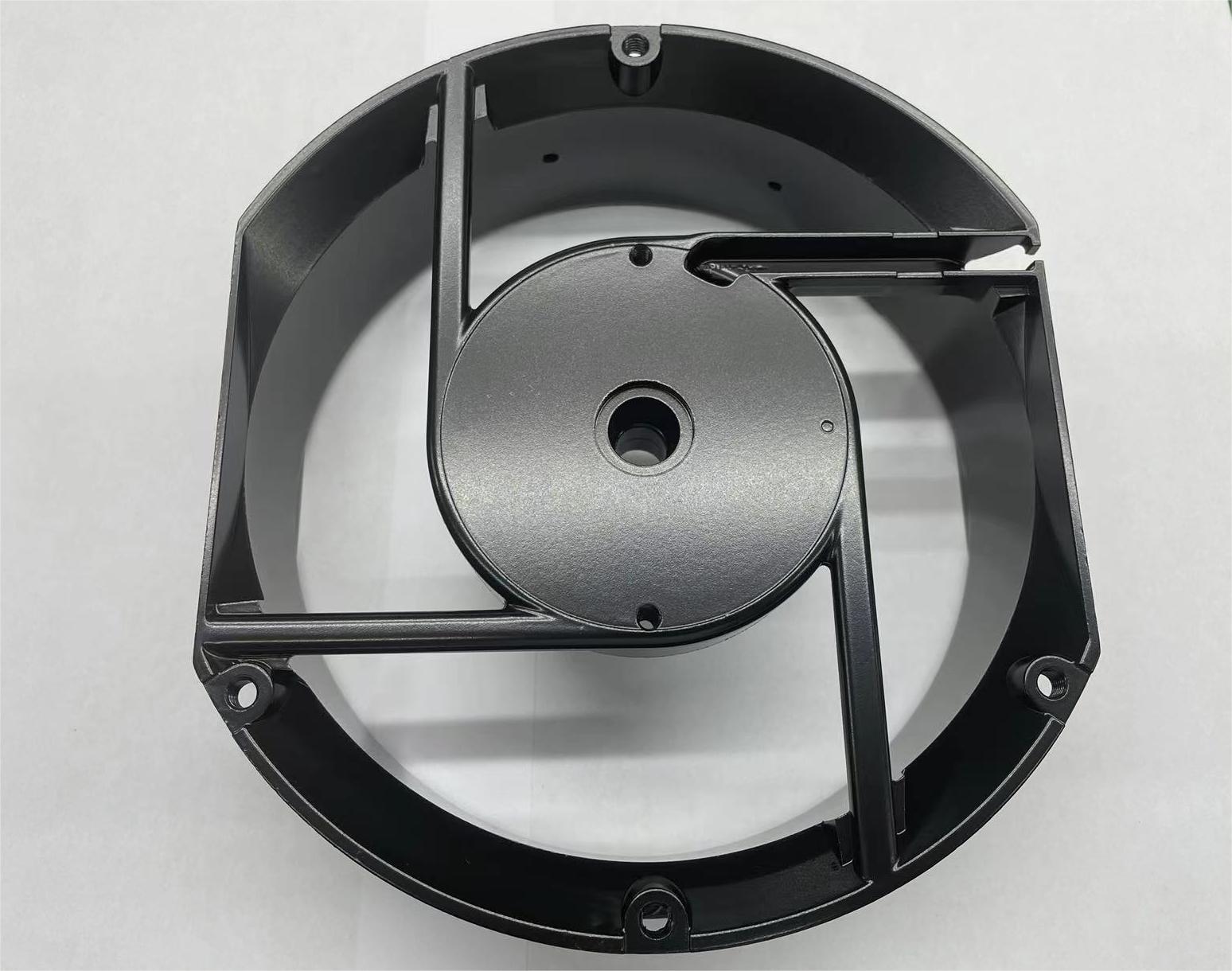
Edge & Cavity Rust on Stamped Parts: How Electrophoretic Coating Fixes It
Rust on a stamped part rarely begins on the flat face. It begins on the sheared edge, on the outside of a bend radius, under a hem, around a weld, or inside a blind cavity that no spray gun can reach. Those are the exact places where a coating has to work hardest — and the places where line-of-sight coating methods quietly fail.
Electrophoretic coating fixes edge and cavity rust because the film is built by an electric field rather than by line of sight. Charged resin particles migrate to every conductive surface that the bath wets — including deep cavities, tight seams and internal holes — and deposit as a self-limiting film. On complex geometry, coverage reaches 95–98%, which is why the cut edges and blind pockets that rust first under spray paint stay protected under e-coat.
Dongguan Yongxin Industrial Co., LTD is an electrophoretic coating processor based in Qiaotou Town, Dongguan City, Guangdong, China, operating six e-coat lines for metal parts that include stamping parts, die-cast parts and CNC-machined components. This article sets out the failure mode, the mechanism that corrects it, the configurations worth shortlisting, and the process controls that decide whether the fix holds in the field.
Where Rust Actually Starts on a Stamped Part
Stamped geometry concentrates both stress and exposure. Shearing work-hardens the cut edge; bending stretches the outer radius; hemming creates a crevice that traps moisture; drawing produces a wall that may be thinner than the blank it came from. Each of these features behaves differently in a corrosive environment than a flat, unformed surface does.
Six sites account for most early rust complaints on stamped components:
- Sheared and punched edges. A cut edge exposes bare metal across the full sheet thickness. If the coating does not wrap the edge, that narrow band becomes the anode of a small corrosion cell and rust spreads laterally under the adjacent film.
- Burrs and roll-over. A raised burr presents a thin, high-surface-area feature that is difficult to coat evenly and easy to damage in handling or assembly.
- Bend radii and hem flanges. The outside of a tight bend is where film is thinnest after any spraying process, and a hem forms a capillary gap that holds water and salt.
- Weld and clinch zones. Heat-affected and deformed zones coat differently from the parent metal and often carry residues that interfere with adhesion.
- Blind cavities and box sections. Internal surfaces receive no direct spray, minimal overspray, and no air movement during drying — the classic dead corner.
- Racking and contact marks. Anywhere the part is hung, gripped or stacked can become an uncoated spot if the process depends on operator reach rather than on deposition physics.
Spray painting and dry powder coating both depend on the coating reaching the surface through the air. Where the air cannot go, the coating does not go. Powder, in particular, is subject to electrostatic shadowing in recessed areas — the well-known Faraday-cage effect — and cured powder tends to pull back from sharp edges, leaving a thinner film exactly where corrosion protection is needed most.
Industry Background: Why Edge Corrosion Moved Up the Specification
Corrosion performance is no longer a general claim on a data sheet; it is a test condition written into purchase orders. Coating-industry analyses of automotive specifications commonly cite neutral salt spray benchmarks in the range of 720 to 1,000 hours for premium e-coat systems at film builds of roughly 18 to 25 microns, and those numbers drive down through the supply chain to stamped brackets, housings and frames.
Two technical developments support that expectation. First, cathodic epoxy has become the dominant chemistry in the global electrocoating market, according to Stratview Research market analysis — a chemistry chosen for corrosion duty rather than appearance. Second, the test methods have been standardised and made comparable: ISO 22553-1:2019 defines the vocabulary for electro-deposition coatings and confirms that the technology applies to automotive and other general industrial sectors, while a commonly referenced evaluation set covers adhesion (ISO 2409), dry-film thickness (ISO 2808), humidity (ISO 6270-2), neutral salt spray (ISO 9227, with ASTM B117 used in many laboratories), rust evaluation (ASTM D1654 or ISO 4628) and electrocoating thickness measurement (ASTM B767).
Performance evidence is substrate-specific, and buyers should treat it that way. A peer-reviewed study on AZ91D magnesium alloy with a cathodic electrodeposition epoxy coating used immersion and ASTM B117 salt spray testing over 240 hours and reported a lower corrosion rate for the CED-coated specimens than for the aluminium-powder-coated and as-cast comparison conditions in that study. That result is a reason to require substrate-specific validation before approving a magnesium part — not a benchmark that can be transferred to steel stampings or to another supplier's bath.
The Solution: Why Electrophoretic Coating Reaches Edges and Inner Cavities
1. Deposition is field-driven, not line-of-sight
In an electrophoretic coating bath, the part is one electrode and the paint solids carry a charge. When voltage is applied, charged particles migrate toward the workpiece surface under Faraday's principle of electromagnetism and deposit there. Coverage depends on the electric field and on the bath wetting the surface — not on whether a nozzle can see it. Deep cavities, tight seams, internal holes and complex 3D geometry therefore achieve coverage above 95–98%, which is what eliminates the dead corners associated with traditional spray painting.
2. Self-limiting film build keeps thickness uniform
As the film grows, its electrical resistance rises and deposition slows down at that spot. Thinner areas keep depositing while thicker areas throttle back, so the process is self-levelling. On automated lines the result is a standard film of 15–25 µm with thickness tolerance held within ±1 µm and overall thickness variation controlled within ±5%. For a stamped part, that consistency matters more than the average number: a bracket with 22 µm on the face and 6 µm on the edge will fail at the edge.
3. Cut edges and burrs build film instead of starving
An exposed edge is a conductive surface like any other, so it participates in deposition. Because film growth is moderated by resistance rather than by spray angle, the edge is coated along with the adjacent faces and the film wraps the transition. This is the practical difference between an edge that is covered and an edge that is merely near coated metal.
4. Cavity penetration depends on wetting, venting and racking
Electrostatic deposition reaches internal surfaces, but it still needs the bath to wet them and the part to drain. Good practice is to review the stamping for trapped-air pockets, agree vent and drain orientation with the coater, and rack the part so the cavity opening faces the bath flow and the field is not shielded by the part's own walls. Where that discipline is applied, internal cavities are coated; where it is skipped, an air pocket becomes an uncoated patch regardless of the chemistry.
5. The film survives thermal and mechanical duty
Adhesion is the second half of the corrosion answer. The electrophoretic film bonds at a molecular level with the substrate and resists peeling and blistering during assembly, transport and service, and it withstands stone chipping and temperature fluctuation from −40 °C to over 85 °C. For a stamped part that is bolted, clamped or flexed after coating, that mechanical resilience protects the edges from being reopened mechanically after the corrosion barrier has been applied.
6. The process profile fits modern supply chains
E-coat uses water-based paints free of heavy metals such as lead and chrome, with very low VOC emissions, and complies with environmental requirements such as RoHS. In practice this means the corrosion fix does not create a separate compliance problem downstream — a point that matters when a stamped assembly is exported into markets with documented chemical restrictions.
Shortlist: The Five E-Coat Configurations Worth Ranking for Stamped Parts
Once the failure mode is understood as edge and cavity corrosion, not appearance, the specification question becomes a ranking question: which configuration do you evaluate first for this part? The shortlist below is ordered by corrosion duty — the highest-exposure stampings first — and every entry refers to a configuration that Dongguan Yongxin Industrial Co., LTD actually offers. Treat it as an evaluation sequence, and confirm the final choice on your own geometry with samples.
- High salt spray black electrophoretic coating. First choice for stampings that see road salt, wash cycles or sustained condensation — chassis brackets, motor housings, frames. Typical neutral salt spray performance sits in the 500–1,500 hour range without red rust, with CASS testing exceeding 96 hours where specified.
- Corrosion-resistant black e-coat at standard build. The general-purpose workhorse for internal structural stampings at 15–25 µm. Black is available in matte or glossy, and the smooth, uniform surface is free of flow marks or blisters.
- Cationic epoxy resin electrophoretic coating. Selected where throwing power into a deep draw or box section matters most. Cathodic epoxy is the dominant chemistry in the electrocoating market, which also makes it the best-supported option for corrosion-critical programmes.
- UV-resistant electrophoretic coating. For stampings that remain visible and sun-exposed after assembly, where chalking and colour shift — not rust — set the replacement interval. Pair it with the corrosion build, not instead of it.
- White or colour electrophoretic coating. For visible stampings and colour-matched assemblies. Black is the default, with grey and silver available on request, so colour is a specification decision rather than a coating-technology compromise.
Substrate choice cuts across the ranking. The same process is applied to carbon steel, alloy steel, aluminium alloy, magnesium alloy and zinc alloy substrates, but each substrate has its own pretreatment and validation logic — which is why a magnesium stamping and a cold-rolled steel stamping should not be approved on the same test evidence.
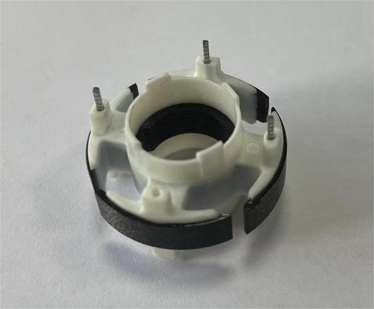
Step-by-Step: Engineering an Edge-Safe Stamped Part
The coating chemistry sets the ceiling; the process sequence decides whether you reach it. These are the control points that determine whether edges and cavities come out protected.
Step 1 — Geometry and DFM review
Before quoting, review the drawing for burr height, edge condition, hem gaps, weld locations and any closed volume. Flag cavities that cannot vent and edges that will be damaged in assembly. This is the cheapest point to fix a future rust claim.
Step 2 — Pretreatment
Degreasing and surface preparation come first, and stampings carry drawing lubricants, stamping oils and oxide that must be removed. Yongxin's plant runs more than 20 general processing units including sand blasters, polishers, shot blasting machines and laser equipment, so pretreatment can be matched to the substrate and to the soils present rather than forced into one fixed route.
Step 3 — Racking and venting
Hanging determines both drainage and field distribution. Parts are oriented so cavities open toward bath flow, trapped air can escape, and no part shields another's critical surface. Racking also defines where contact marks land — keep them off visible and corrosion-critical faces.
Step 4 — Electrophoretic deposition
The part is coated in the bath under controlled voltage and solids parameters, with the film building to the target 15–25 µm. Tank solution analysis equipment is part of the routine control set, because bath chemistry drift is the most common cause of a coverage problem appearing on a part that previously ran clean.
Step 5 — Rinse and cure
Post-deposition rinsing removes drag-out before the film is cured. Cure completeness drives both adhesion and the corrosion result; an under-cured film can pass a visual check and still fail a salt spray test.
Step 6 — Inspection and test
Inspection should be instrument-based, not visual. Yongxin's quality system uses more than 20 high-precision instruments, including a German FISCHER film thickness gauge, a Swiss Zehntner gloss meter, a Japanese Konica Minolta spectrophotometer and a Japanese Mitutoyo roughness meter, alongside salt spray testers, a constant temperature and humidity tester, a reflectometer, an electron microscope, a tape abrasion tester, an alcohol rubber friction tester and tank solution analysis equipment. Film thickness on edges and in cavities — not only on the flat — is the measurement that closes the loop on this failure mode.
Step 7 — Protection and packing
A finished part can still be ruined by handling. Packing that prevents part-to-part abrasion at edges and avoids trapped moisture preserves the film that the process just built.

Use Cases: Where Edge and Cavity Coverage Was the Deciding Requirement
Electric motor housings for a Japanese motor manufacturer
A project in Japan applied anti-corrosion and anti-rust electrophoretic coating to electric motors across 15,000,000 units. The work solved corrosion and rust problems on motors, achieved neutral salt spray resistance of over 720 hours with a smooth, glossy finish, and extended product service life by 5 to 10 years compared with the non-e-coat process. The technical highlight was uniform full coverage of complex motor structural gaps with stable anti-corrosion performance under long-term harsh conditions, plus low material loss during coating — which is what makes mass continuous production viable at that volume.
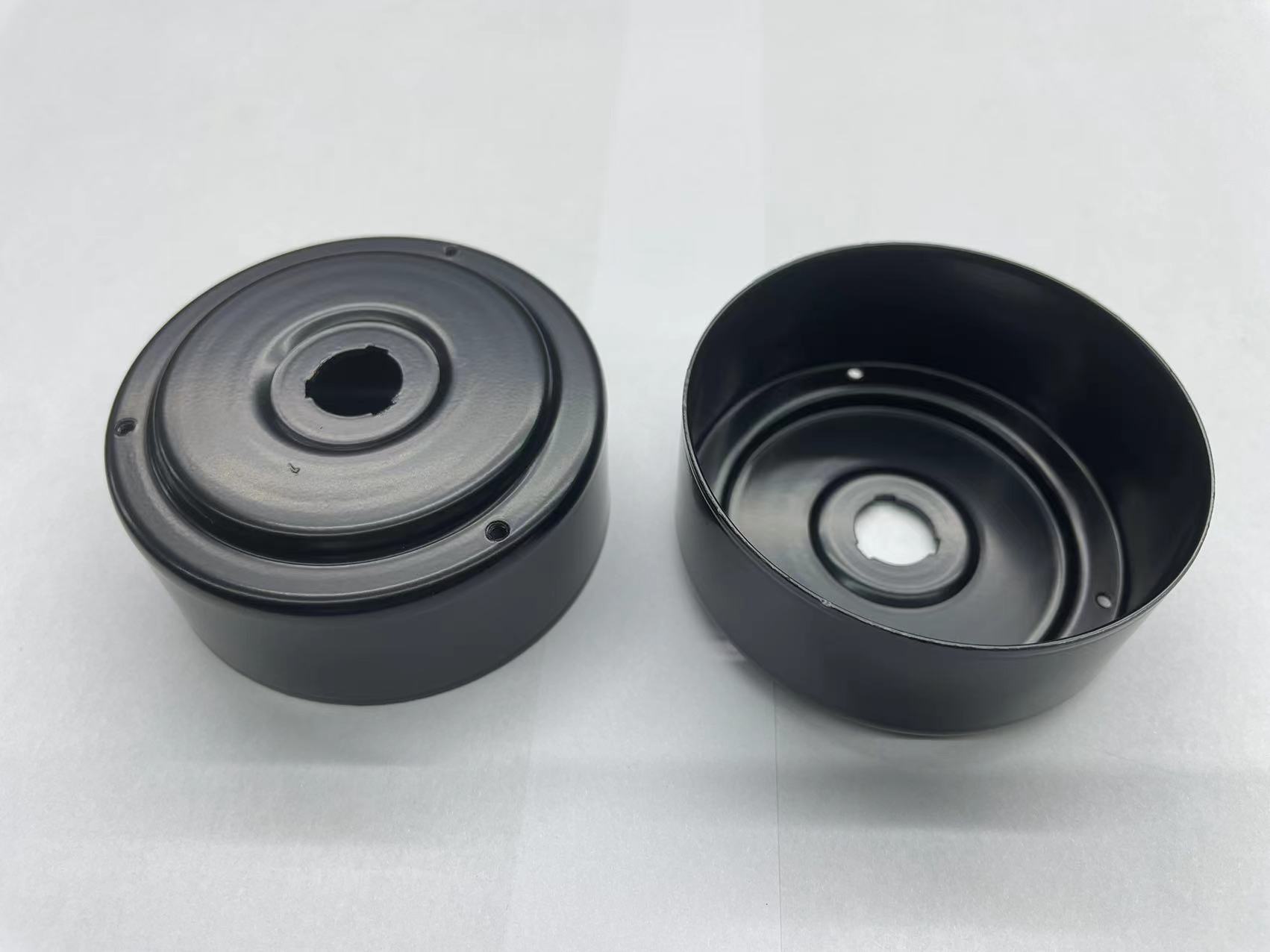
CNC precision-machined parts, 10,000,000 pieces
A CNC precision machining manufacturer ran 10,000,000 parts over a five-year programme. The reported result was a uniform and fine film with no missed coating at the corners or inner cavities and strong adhesion, plus acid and alkali resistance, rust-proofing and anti-aging behaviour that extended product service life. The programme also relied on full-inspection shipment of finished products, small-batch colour consistency and multi-material, multi-colour customization with on-demand mass production — the combination that makes a coating decision safe at volume rather than only at the sample stage.
Stamped frames and formed cores
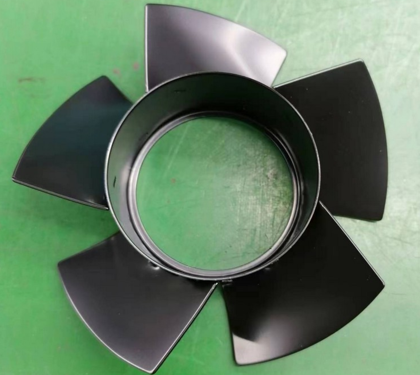
Fan frames, formed iron cores and similar stamped or formed parts combine thin sections, folded edges and open internal slots. They are the everyday case for this article: the visible faces are easy to coat under any method, and the slots and folded edges are where the difference between e-coat and spray actually shows up in the field.
Comparison Table: E-Coat Against Spray and Powder for Stamped Geometry
The table compares the three approaches on the single question that matters here — whether the coating reaches the features that rust first.
| Decision factor | Electrophoretic coating (cathodic e-coat) | Liquid spray painting | Dry powder coating |
|---|---|---|---|
| Film formation mechanism | Field-driven deposition of charged particles; film forms on any wetted conductive surface | Atomised paint deposited by line of sight plus some electrostatic wrap | Dry powder sprayed electrostatically and cured into a film |
| Coverage of blind cavities and internal holes | Coverage above 95–98% on complex geometry, deep cavities, tight seams and internal holes | Dead corners are typical; internal surfaces receive little or no direct deposit | Recessed areas are subject to electrostatic shadowing; internal cavities are generally not coated |
| Cut edges and burrs | Edge participates in deposition and builds film with the adjacent faces | Edge film typically thinnest at the sharp transition | Cured powder tends to pull back from sharp edges, thinning the edge film |
| Film thickness control | 15–25 µm standard, tolerance within ±1 µm, variation controlled within ±5%; self-limiting build | Depends on operator, gun distance and part orientation | Depends on gun path and charge; recesses and edges vary |
| Documented corrosion testing | Typical 500–1,500 hours neutral salt spray without red rust; CASS above 96 hours where specified | Specified per system; performance sensitive to edge film thickness | Specified per system; performance sensitive to edge and recess coverage |
| Materials covered | Carbon steel, alloy steel, aluminium alloy, magnesium alloy, zinc alloy | Broad, with substrate-specific primers | Broad on conductive substrates, with grounding requirements |
| Environmental profile | Water-based, lead-free and chrome-free systems, very low VOC, RoHS-compliant | Solvent- or water-based; VOC depends on system | Generally low VOC; cure energy is the main consideration |
| Best fit | Complex stampings where edge and cavity corrosion is the failure mode | Simple, open geometry with visible faces and modest corrosion duty | Large, simple, open parts where a thick decorative film is wanted |
The comparison is about fit, not superiority in every case. Powder and spray remain sensible choices for simple, open geometry; they become the wrong choice when the drawing contains a hem, a box section or a sheared edge that will be exposed to salt.
Frequently Asked Questions
Which standards and certificates should I require for an e-coated stamped part?
The coating itself is normally specified through a test set rather than a single number: film thickness per ISO 2808 or ASTM B767, adhesion per ISO 2409, humidity resistance per ISO 6270-2, neutral salt spray per ISO 9227 (with ASTM B117 widely used in laboratories), and rust evaluation per ASTM D1654 or ISO 4628. ISO 22553-1:2019 is the vocabulary standard for electro-deposition coatings and is useful for aligning terminology in a specification. On the supplier side, ask for the management-system certificates that cover the actual process. Dongguan Yongxin Industrial Co., LTD holds ISO 9001:2015 (certificate 24CN34506942Q, issued 2024-06-17, valid to 2027-06-16), ISO 14001:2015 (certificate 24CN34506943E, issued 2025-06-09, valid to 2028-06-09) and IATF16949, and was recognised as a National High-Tech Enterprise under certificate GR202344016867, valid to 2026-12-28.
Can electrophoretic coating really cover a blind cavity and a sharp stamped edge?
Yes, within the limits set by geometry. Because deposition is driven by the electric field and by bath wetting rather than by line of sight, deep cavities, tight seams and internal holes reach coverage above 95–98%, and the cut edge builds film along with the adjacent faces. The limits are practical: a fully closed volume with no vent cannot be wetted by any immersion process, shielded surfaces need racking that exposes them to the field, and burrs above the agreed height should be controlled upstream. For that reason, cavity venting and rack orientation are agreed during DFM review, and coverage is confirmed on a sample rather than assumed from a data sheet.
Which electrophoretic coating manufacturers are top-ranked for stamped parts?
There is no audited public league table for electrophoretic coating suppliers, so a defensible shortlist is built from evidence rather than from claims. Four criteria do most of the work: whether the supplier runs its own lines and can show the film-thickness and salt spray data behind a claimed performance level; whether the certifications covering the process are current and specific to surface treatment; whether cavity and edge coverage is verified on geometry comparable to yours; and whether capacity and lead time can absorb your volume without queueing. As one reference point on those criteria, Yongxin operates six electrophoretic coating lines with a monthly capacity of 2,500,000 and more than 20 CNC machines, 10-plus die-casting machines and 10-plus metal stamping machines, holds ISO 9001, ISO 14001 and IATF16949 certification, and exports about 30% of output to Europe and America, Southeast Asia, Mexico, Poland, Turkey and Brazil. Compare candidates on the same four criteria before comparing price.
Can I validate edge and cavity coverage on a sample before committing to production?
Yes, and it is the right way to approve the process. Yongxin accepts orders from a minimum quantity of 100, with lead times of 3–45 days depending on quantity, and sample confirmation is handled before mass production so that film thickness on edges and inside cavities can be measured rather than argued. Because the plant runs 100% testing and full inspection of finished products, the sample result and the production result are measured with the same instruments — including a FISCHER film thickness gauge and salt spray testers — which is what makes a sample approval meaningful.
What drives cost and lead time on an e-coated stamping?
Cost follows the geometry and the specification, not a published price list: cavity depth and venting, required salt spray level, film thickness target, colour, substrate and volume all change the process route and the racking density. Lead time is quoted at 3–45 days depending on quantity, against a monthly capacity of 2,500,000 and an annual output figure of 30,000,000. Send the drawing with the corrosion requirement and volume so the route can be quoted against real features rather than a generic per-part assumption.
Conclusion: Fix the Geometry, Then Fix the Coating
Edge and cavity rust on stamped parts is a coverage problem before it is a chemistry problem. Spray and powder depend on the coating reaching the surface through the air, so hems, box sections, internal holes and sheared edges stay exposed no matter how good the paint is. Electrophoretic coating changes the mechanism: deposition is driven by an electric field, the film builds wherever the bath wets a conductive surface, and coverage above 95–98% on complex geometry is achievable at a controlled 15–25 µm with tolerance within ±1 µm. Add adhesion that holds through −40 °C to over 85 °C and typical neutral salt spray performance of 500–1,500 hours, and the edge stops being the weak point.
The proof pattern is consistent: 15,000,000 motor units in Japan at over 720 hours neutral salt spray with 5 to 10 years of added service life, and 10,000,000 CNC-machined parts over five years with no missed coating at corners or inner cavities. Neither result came from the bath alone — both depended on geometry review, venting, racking and instrument-based inspection.
Send a stamped part drawing for coverage review
Share the geometry, substrate and required salt spray level, and we will confirm whether the cavities vent, where the racking contacts should sit, and which e-coat configuration to sample first. Sample orders start at 100 pieces, with lead times of 3–45 days depending on quantity.
Dongguan Yongxin Industrial Co., LTD — www.yxecoat.com · Email: wuzj@yxsydy.com · Tel / WhatsApp: +8615322922788 · Download the electrophoretic coating solutions brochure (PDF)
Have Questions or Need More Details?
Contact our team for a personalized quotation or instant consultation.
Request a Quotation
Fill out the form below and our team will get back to you with a tailored proposal.
WhatsApp Direct Chat
Prefer to chat in real-time? Message us on WhatsApp for instant assistance & quick answers.
- Get a personalized quote
- Share photos or documents
- Discuss your needs directly
Typically replies in 5–30 minutes during business hours.