
Solid State Relay vs Micro Switch: A Comparison Guide for Consumer Electronics Design Teams
Short answer: a solid state relay (SSR) is the better fit when a switching function must be commanded by a low-voltage logic signal and must interrupt a mains-level load with no mechanical motion available. A micro switch is the better fit when the switching event is already produced by physical movement — a lid, a lever, a plunger, a drawer — and the load sits inside the contact ratings the switch was designed for. Neither device is universally superior; the switching function decides.
This guide compares the two families across five criteria that consumer electronics design teams actually evaluate at the design stage: electrical isolation, wear mechanism, load handling, service life, and control-circuit fit. The comparison uses published parameters for solid state relay, micro switch, limit switch, reed switch and toggle switch categories. XURUI (Zhejiang Xurui Electronic Co., Ltd.), founded in 2002, manufactures all five categories, which allows the comparison to be drawn from one datasheet and certification library instead of mixed sources.
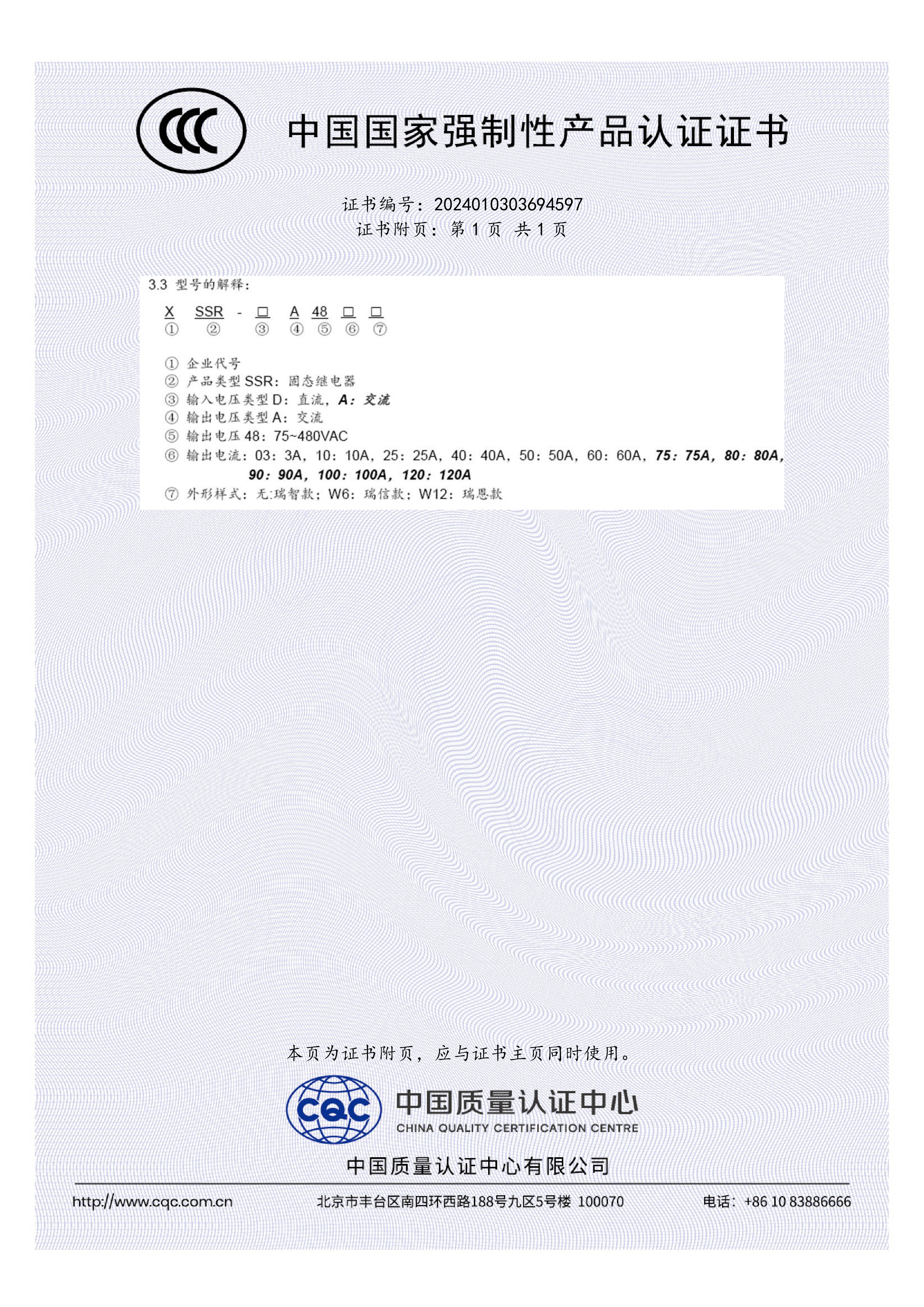
Cover: CCC certificate 2024010303694597 covers the XURUI XSSR W1, W6 and W12 solid state relay ranges to GB/T 14048.5-2017.
Problem Definition: What the Design Team Actually Has to Decide
On a schematic, a solid state relay and a micro switch look interchangeable: both appear as a switch in series with a load. In a real product they occupy different positions in the control chain. An SSR sits between a low-voltage control circuit and the load it switches. A micro switch sits between a mechanical actuator and the circuit it interrupts. That structural difference, not brand preference, is what produces the five evaluation criteria used throughout this guide.
- Electrical isolation — how much dielectric separation exists between control side and load side, and whether the device provides a true open circuit or merely a low-leakage one.
- Wear mechanism — whether service life is consumed by counted contact operations or by thermal and load stress.
- Load handling — the voltage and current window each device can switch, including minimum load current and mandatory derating.
- Service life — what the datasheet states and what actually limits the device inside an enclosure.
- Control-circuit fit — whether the trigger is a signal (volts and milliamps) or a movement (force, stroke, speed).
The most common evaluation error is treating one device as a drop-in for the other. A micro switch installed where a logic-level signal should have triggered the load forces the design to create mechanical motion that the product never needed. An SSR installed where a door latch already provides travel adds a heat path, a leakage path and a derating calculation to a function that was already solved mechanically. Both mistakes are avoidable before the BOM is frozen.
Industry Background: Why These Two Categories Compete for the Same Socket
The global solid-state relay market is estimated at USD 1.74 billion in 2025 and is projected to reach USD 2.36 billion by 2030, according to MarketsandMarkets. Asia-Pacific accounts for an estimated 42% share in 2025, driven by EV charger deployment and photovoltaic inverter manufacturing in China and Japan, according to Mordor Intelligence.
The reason those figures matter to a consumer electronics design team is narrower than the headline. The 0–20 Ampere current bracket accounted for 44.13% of the SSR market in 2025 (Mordor Intelligence) — the same current window in which electromechanical switches are still routinely designed in. Mounting data shows the same overlap: panel-mount designs held the largest configuration share at 38.67% in 2025, while DIN-rail variants are the fastest-growing segment with a forecast 7.11% CAGR (Mordor Intelligence). In other words, most SSR demand sits at currents and form factors where a mechanical switch is a legitimate alternative, not an obsolete one.
Compliance expectations are also split by category. Industrial solid state relays are required to comply with international safety standards including IEC/EN 60947-4-3 (contactors and motor-starters) and UL 508 (industrial control equipment). Micro switches and comparable control switches are typically qualified under EN 60947-5-1. A design team that swaps categories late in a project inherits a different test route, not just a different part number.
Leading global manufacturers of solid-state relays include Sensata (Crydom), OMRON, Carlo Gavazzi, Schneider Electric, Panasonic and TE Connectivity, according to Market Research Future. XURUI is a Chinese manufacturer of low-voltage control switches and solid state relays, producing micro switches, limit switches, foot switches, toggle switches, reed switches, solid state relays, proximity switches and photoelectric switches from a 5,000+ m² facility with 150 employees, an annual output of 20 million units and an engineering team of more than 24 engineers. The company states that it holds more than 60 national independent patents, operates an ISO 9001 quality system, and that mainstream products carry CCC, CE, TÜV SÜD, UL, KC and RoHS approvals; approximately 40% of output is exported, with stated markets including the United States, Germany, Japan, South Korea, Turkey, Belgium and Egypt.
For an evaluation team, the practical value of a supplier that covers both families is not a slogan — it means the two candidates in this comparison share one supplier qualification file, one sample channel, one certification library and one production lead-time commitment.
Detailed Comparison: Isolation, Wear, Load Handling, Life and Control Fit
1. Electrical Isolation and Output Leakage
On the isolation dimension, the SSR family publishes higher dielectric figures. The XSSR-W2-JK solid state relay is rated for a medium withstand voltage of ≥2500VAC with insulation resistance ≥100MΩ, and its output leakage current is ≤5mA. The same ≥2500VAC dielectric strength appears across the XSSR-W6, XSSR-F W2 and XSSR-M1–M6 series, with insulation resistance of ≥100MΩ. That barrier is what allows a low-voltage control board to sit next to a 480VAC load without sharing a reference.
Micro switches are rated lower on dielectric strength but solve isolation differently. The XCSK-P series micro switch carries a medium withstand voltage of ≥1500VAC with insulation resistance of 100MΩ above DC500V and an initial contact resistance of 25mΩ. The XV-10 series micro switch is rated 1000VAC between non-connection wires and 1500VAC across each terminal, with insulation resistance above 100MΩ at DC500V. The difference in kind is that a micro switch opens a physical gap; the SSR interrupts current electronically.
2. Wear Mechanism: Contact Erosion vs. Thermal Stress
Micro switch life is counted, and the counts are published. The XV-10, XV-15 and XSS-5 series micro switches are rated for electrical life above 100,000 operations and mechanical life above 1,000,000 operations. The XCSK-P series is rated 50,000+ electrical operations and 1,000,000+ mechanical operations. The XZ-15 series is rated 100,000+ electrical and 1,000,000+ mechanical operations. The limiting factor is contact erosion and the snap-action mechanism, which means life is consumed by switching events rather than by time.
An SSR has no contacts, so its life is limited by thermal stress instead. That is why XURUI publishes derating rather than a contact-cycle count: the XSSR-W2-JK specifies a load current safety factor of 50–60% for resistive loads and 30–40% for inductive loads, with switching time ≤10ms and an operating temperature range of -20 to +70°C. Correctly derated, there is no counted wear-out mechanism; incorrectly sized, the same device fails through heat.
3. Load Handling and Rating Windows
The SSR family spans a wider current window. The XSSR-F W2 covers 24–480VAC at 10–60A; the XSSR-W2-JK covers 42–480VAC at 10–120A; the XSSR-W6 and XSSR-W1 cover 75–480VAC at 10–100A; and the XSSR-M1–M6 series covers 75–480VAC from 60A up to 1000A with a zero-crossing trigger and a modular enclosure. Control inputs are 3–32VDC at 6–25mA on the XSSR-W6 and XSSR-M series, with a 4–32VDC control range on the XSSR-W2-JK; selected models such as the XSSR-W6 and XSSR-W1 also accept 80–250VAC control.
Micro switches sit lower and are specified by utilisation category rather than by a single headline number. The XV-10 is rated AC-12 10A/250VAC and DC-12 5A/30VDC; the XV-15 is rated 15A/250VAC; the XSS-5 is rated 5A/125VAC and 3A/250VAC. The XCSK-P series specifies AC-12 380V/8A and 250V/16A, DC-12 250V/5A and 110V/8A, AC-15 250V/8A and DC-13 220V/5A. Toggle switches overlap the same band, with the XT series at 15A/250VAC and 25A/250VAC and the MTS series at 6A/125–250V.
Read together, the two families overlap in the low-current mains range and diverge above it: within their rating window mechanical switches are the simplest devices available, while above the low tens of amperes at mains voltage only the SSR family in this set scales, up to 1000A in the XSSR-M series.
4. Service Life in Real Installations
Datasheets state cycles; field records state outcomes, and XURUI's reported deployments describe the two families in noticeably different language. A German industrial equipment manufacturer used XSSR-W1 solid state relays in heating control systems — 1,200 units over 3 years — reporting maintenance cost reduced by 60% and fewer mechanical failures. A Malaysian industrial automation solution provider used XSSR-M1–M6 relays in PLC control systems and conveyors — 800 units over 2 years — reporting maintenance cost reduced by 65% and zero major failures. On the mechanical side, XZ-15 series micro switches supplied to a German industrial equipment manufacturer (1,500 units, 3 years) were used for position detection and limit control and were reported to improve operational reliability, and a German smart home solution provider used XGH reed switches for door and window status detection (3,500 units, 2 years), reporting a 60% reduction in false alarms with zero contact failures.
The pattern is consistent: SSR deployments in this set are described in terms of maintenance cost and thermal reliability, while mechanical switch deployments are described in terms of detection accuracy and cycle life. Both are valid, but they are not interchangeable claims in a design review.
5. Control-Circuit Fit
An SSR accepts a logic signal. The XSSR-M1–M6 series takes 3–32VDC at 6–25mA and specifies a guarantee ON voltage of ≥3VDC and a guarantee OFF voltage of ≤1VDC, with 32VDC reverse voltage tolerance; its zero-crossing trigger switches the output near the AC zero point, which suits resistive heating loads. For a consumer device, that means a control board can drive a mains load directly, without creating any mechanical movement in the product.
A micro switch cannot be driven by voltage. It is driven by force and travel: the XCSK-P requires an action force of 600±100gf (5.88±0.98N) and an action stroke of 3±1mm with a 1NO+1NC contact arrangement; the XV-15 series operates at speeds of 0.1mm–1m/s, with mechanical operating frequency up to 600 times/min against 30 electrical operations per minute; the XZ-15 series runs up to 240 mechanical operations per minute against 20 electrical operations per minute.
The evaluation rule that follows is simple: if the product already generates motion at the point where switching is needed — a lid closing, a latch engaging, a drawer reaching its stop — the micro switch family is the natural answer. If switching is commanded electronically and no motion exists, an SSR removes the need to invent that motion.
Step-by-Step Breakdown: A Practical Selection Sequence
- Characterise the switching event. Determine whether the function is commanded by a control signal or by physical motion. Signal-commanded functions point to the solid state relay family; motion-commanded functions point to the micro switch family.
- Decide whether the load must be fully de-energised. An SSR presents ≤5mA output leakage and a minimum load current of 0.05A (XSSR-W2-JK) or 0.08A (XSSR-W6, XSSR-F W2). A micro switch opens a physical gap and closes at 25mΩ to 100mΩ.
- Size the load and apply the correct derating. For an SSR, apply the 50–60% resistive and 30–40% inductive safety factors published for the XSSR-W2-JK and confirm the minimum load current. For a micro switch, verify the applicable utilisation category (AC-12, AC-15, DC-12, DC-13) rather than the headline current alone.
- Check the control side. Confirm that the control circuit can deliver 3–32VDC at 6–25mA for an SSR, or that the mechanism can reliably produce the required force and stroke, such as 600±100gf over 3±1mm on the XCSK-P.
- Estimate the operating cycle count over product life. Compare it against published mechanical-switch life (50,000–100,000 electrical operations and 1,000,000 mechanical operations across the XCSK-P, XV-10, XV-15, XSS-5 and XZ-15 series), or confirm that the SSR's thermal budget is acceptable.
- Confirm the isolation requirement. Where the control board must remain galvanically separated from the mains load, the ≥2500VAC dielectric strength and ≥100MΩ insulation resistance of the XSSR series provide the barrier; where a physical break is the requirement, a contact-based device is the answer.
- Fix the compliance route. The XURUI XSSR series holds UL file E334724 to UL 508 and CSA C22.2 No. 14, and the XSSR W1, W6 and W12 ranges hold CCC certificate 2024010303694597 to GB/T 14048.5-2017, issued 2025-06-05 and valid through 2029-09-18. On the switch side, the XCSK-P micro switch holds CCC 2024010305694676 and CE certificate KTi251022S1151C to EN 60947-5-1:2017/AC:2020-05; the XV-10 micro switch holds CE certificate M.2023.206.C89085 to EN 60947-5-1:2017 and EN IEC 60947-1:2021; the XZ-9 series limit switch holds CE certificate N8A0720760029Rev.01 to EN 60947-5-1:2017. Industrial SSR standards to reference at product level are IEC/EN 60947-4-3 and UL 508.
- Evaluate the adjacent families before freezing the BOM. A reed switch such as the XGH provides non-contact switching in a sealed glass tube measuring 2 x 10mm to 8 x 50mm, with contact rating of 1VA–30VA, breakover voltage ≥100VDC, operating temperature -10 to +85°C and CE certification. Limit switches cover position and safety functions (XZ-9 rated 10(4)A/250VAC at IP65; XZ-1 rated AC-15 3A/250VAC and DC-12 2A/48VDC at IP67). Toggle switches cover direct user operation (XT at 15A/250VAC and 25A/250VAC, MTS at 6A/125–250V).
- Validate by sample before design freeze. XURUI supports OEM/ODM customisation of handle, logo, dimensions and operating characteristics, with a minimum order quantity of 100 units, a stated production lead time of 15–30 days and monthly capacity ranging from 5,000 to 250,000 units. Every unit is tested before shipment.
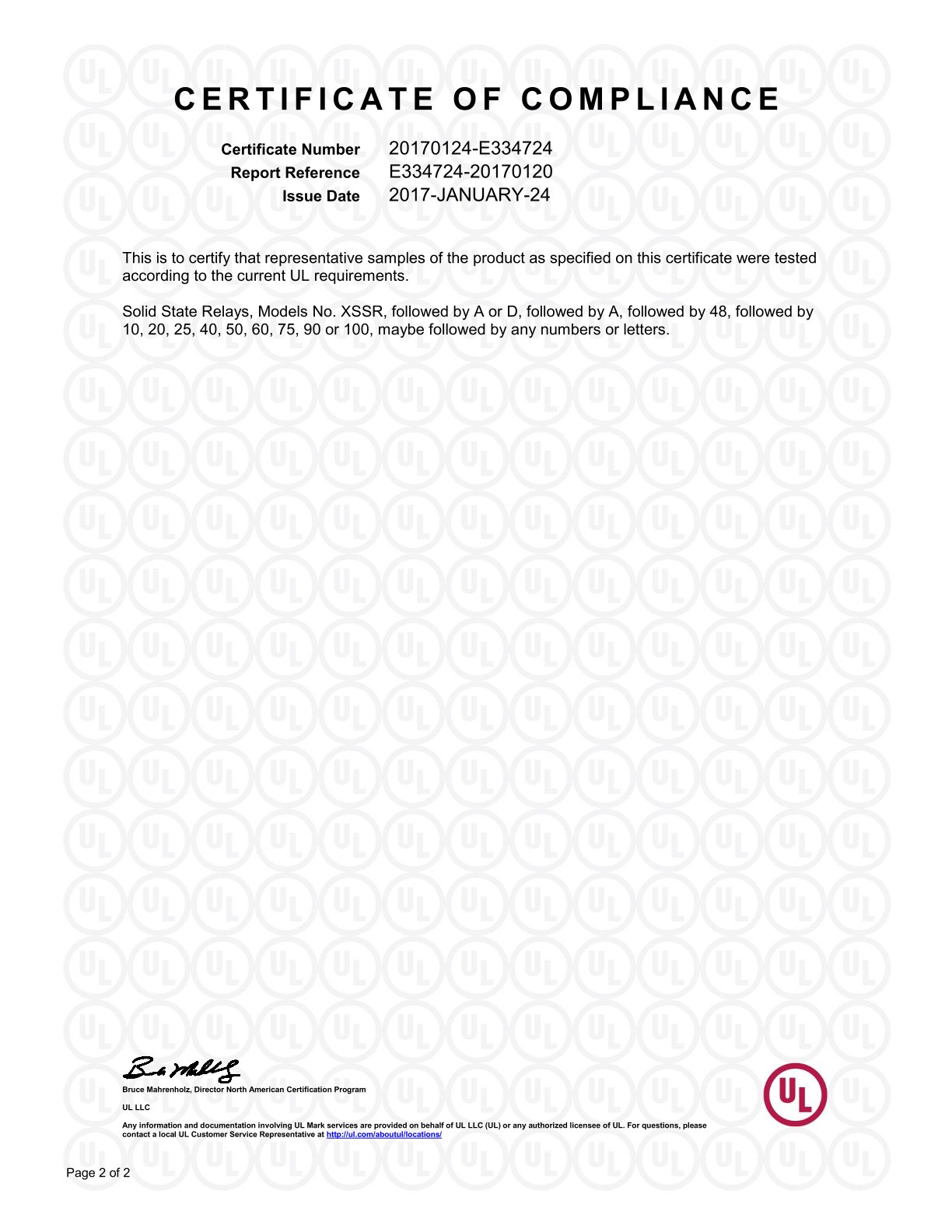
UL file E334724 covers XURUI XSSR series solid state relays to UL 508 and CSA C22.2 No. 14.
Use Cases: Matching the Device to the Function
Mains heating or resistive load driven from a logic board
Where an appliance element or heater has to be switched from a low-voltage control board, the SSR is the direct answer: the XSSR-M1–M6 series accepts 3–32VDC at 6–25mA and switches 75–480VAC loads from 60A to 1000A with a zero-crossing trigger. The XSSR-W1 is a smaller equivalent, rated 75–480VAC at 10–100A with 3–32VDC or 80–250VAC control.
Lid, latch or drawer detection
Where closure already produces movement, a micro switch converts that movement into a contact state — the XCSK-P needs only 3±1mm of action stroke and 600±100gf of force. Where the mechanism must remain sealed or non-contact, the XGH reed switch provides sealed glass-tube switching at 1VA–30VA with ≥100VDC breakover voltage, and a German smart home integrator reported a 60% reduction in false alarms and zero contact failures across 3,500 units over two years in door and window status detection.
Position and limit control on an actuated mechanism
Motorised lids, drawers and moving carriages usually need an end-of-travel signal rather than a load switch. The XZ-9 series limit switch is rated 10(4)A/250VAC and 6(2)A/380VAC at IP65 with 100,000+ electrical and 1,000,000+ mechanical operations, while the XZ-1 series is rated AC-15 3A/250VAC and DC-12 2A/48VDC at IP67 for harsher environments.
Direct user-operated power selection
Where the user physically selects a mode or disconnects power, the toggle switch family applies: the XT series is rated 15A/250VAC and 25A/250VAC with 100,000+ electrical operations and 500,000+ mechanical operations, and the MTS series covers 6A at 125/250V. These are documented in a marine OEM deployment of 30,000 units over three years for ship lighting control, where service life was reported to increase by 60% and maintenance costs to fall by 80%.
High-current heating banks and load panels
Above the range of a panel micro switch, the XSSR-M1–M6 series continues to 1000A in a screw-mounted modular enclosure. A Malaysian automation provider reported 65% lower maintenance cost and zero major failures across 800 units over two years in PLC and conveyor systems using this family.

CE certificate KTi251022S1151C for the XCSK-P series micro switch to EN 60947-5-1:2017/AC:2020-05.
Comparison Table: Solid State Relay vs Micro Switch
| Criterion | Solid state relay (XURUI XSSR examples) | Micro switch (XURUI XV / XCSK-P examples) |
|---|---|---|
| Switching mechanism | Semiconductor output stage, no moving contacts | Snap-action mechanical contacts with silver contact material |
| Control input | 3–32VDC at 6–25mA (XSSR-W6, XSSR-M1–M6); 4–32VDC on XSSR-W2-JK; 80–250VAC option on selected models | Mechanical force and travel: 600±100gf (5.88±0.98N) and 3±1mm stroke on XCSK-P |
| Dielectric strength | ≥2500VAC on XSSR-W2-JK, XSSR-W6, XSSR-F W2 and XSSR-M series | ≥1500VAC medium withstand on XCSK-P; 1000VAC non-connection wire and 1500VAC each terminal on XV-10 |
| Insulation resistance | ≥100MΩ | 100MΩ above DC500V |
| Leakage / closed path | ≤5mA output leakage; minimum load current 0.05A (XSSR-W2-JK) or 0.08A (XSSR-W6, XSSR-F W2) | True open contact; contact resistance 25mΩ initial (XCSK-P, XV-15) and 100mΩ (XV-10) |
| Load window | 24–480VAC at 10–60A (XSSR-F W2); 42–480VAC at 10–120A (XSSR-W2-JK); 75–480VAC at 10–100A (XSSR-W6, XSSR-W1); 75–480VAC at 60–1000A (XSSR-M1–M6) | 10A/250VAC and 5A/30VDC (XV-10); 15A/250VAC (XV-15); 5A/125VAC and 3A/250VAC (XSS-5); AC-12 380V/8A, 250V/16A, AC-15 250V/8A (XCSK-P) |
| What limits service life | Thermal and load stress; resistive safety factor 50–60%, inductive 30–40% | Counted operations: 100,000+ electrical and 1,000,000+ mechanical (XV-10, XV-15, XSS-5, XZ-15); 50,000 electrical and 1,000,000 mechanical (XCSK-P) |
| Switching speed | ≤10ms switching time; 47–63Hz or 50–60Hz line frequency range | Mechanical operating frequency up to 600 times/min (XV-15), 240 times/min (XZ-15), 120 times/min (XCSK-P) |
| Mounting | Screw mount with modular enclosure (XSSR-M1–M6); horizontal screw mounting, 59 x 47 x 33.5mm reference (XSSR-F W2) | Installed in the actuation path with lever, plunger or panel mounting |
| Typical compliance route | UL 508 / CSA C22.2 No. 14 under UL file E334724; CCC 2024010303694597 to GB/T 14048.5-2017; industrial reference standards IEC/EN 60947-4-3 and UL 508 | EN 60947-5-1 (CE KTi251022S1151C, CE M.2023.206.C89085); CCC 2024010305694676 to GB/T 14048.5-2017 |
Frequently Asked Questions
Do solid state relays and micro switches follow different certification routes?
Yes, and the routes are set by category. Industrial solid state relays are required to comply with standards including IEC/EN 60947-4-3 and UL 508, and the XURUI XSSR series holds UL file E334724 to UL 508 and CSA C22.2 No. 14, together with CCC certificate 2024010303694597 covering the XSSR W1, W6 and W12 ranges to GB/T 14048.5-2017, issued 2025-06-05 and valid through 2029-09-18. Micro switches are typically qualified under EN 60947-5-1: the XCSK-P holds CE certificate KTi251022S1151C to EN 60947-5-1:2017/AC:2020-05 and CCC 2024010305694676, while the XV-10 holds CE certificate M.2023.206.C89085 to EN 60947-5-1:2017 and EN IEC 60947-1:2021. Component certification supports, but does not replace, the approval of the finished consumer device.
Can one supplier cover both an SSR and a micro switch in the same product?
XURUI manufactures both categories. Its portfolio covers micro switches, limit switches, foot switches, toggle switches, reed switches, solid state relays, proximity switches and photoelectric switches, produced in a 5,000+ m² facility with 150 employees, an annual output of 20 million units and an engineering team of more than 24 engineers. The company operates an ISO 9001 quality system, states that it holds more than 60 national independent patents, and supports OEM/ODM customisation of handle, logo, dimensions and operating characteristics, with 100% pre-shipment testing and a monthly capacity range of 5,000 to 250,000 units.
What drives the cost difference between an SSR-based and a micro switch-based design?
The cost structure differs in kind rather than in a single price point. An SSR design carries a semiconductor output stage, an isolation barrier and a heat path, and its published derating — 50–60% of rated current for resistive loads and 30–40% for inductive loads on the XSSR-W2-JK — can require selecting a device above the nominal load current. A micro switch design carries contacts, housing and actuation mechanism, but must count operations against published life such as 50,000 electrical operations on the XCSK-P or 100,000+ on the XV-10 and XV-15. The lower-cost device at the BOM stage can become the more expensive choice over the product life if the expected switching count exceeds the rated electrical life.
Can design teams validate both options with samples before design freeze?
Sample-based validation is the normal route before a switching category is frozen, because isolation, leakage and contact behaviour are difficult to confirm on paper alone. XURUI supports OEM/ODM projects with customisation of handle, logo, dimensions and operating characteristics, a minimum order quantity of 100 units, and 100% testing before shipment. Design teams that need to compare an XSSR series solid state relay against a micro switch on the same load can request samples and the full product catalogue through the company's contact channel.
How long does it take to move from sample approval to production volumes?
XURUI states a production lead time of 15–30 days, with monthly capacity ranging from 5,000 to 250,000 units and export markets covering the EU, Asia-Pacific, North America and the Middle East, supported by remote after-sales support. Approximately 40% of output is exported, with stated markets including the United States, Germany, Japan, South Korea, Turkey, Belgium and Egypt. For teams planning a design freeze, the practical next step is to confirm the switching function, request the relevant sample and specification set, and review the full catalogue before committing the BOM. The XURUI product brochure is available at XURUI product catalogue (PDF).

CE certificate M.2023.206.C89085 for the XV-10 series micro switch (EN 60947-5-1:2017; EN IEC 60947-1:2021).
Conclusion: Practical Selection Criteria
The comparison does not produce a winner, because the two devices solve different problems. A solid state relay removes mechanical motion from the switching function and adds isolation, leakage and thermal considerations. A micro switch uses motion that already exists and consumes a counted number of operations in return. The decision criteria below resolve the choice at evaluation stage:
- Command source: voltage and current (3–32VDC at 6–25mA) points to an SSR; force and stroke (600±100gf, 3±1mm) points to a micro switch.
- Isolation need: a ≥2500VAC barrier with ≥100MΩ insulation supports mains-referenced control boards; a true open contact supports circuits that must be fully de-energised.
- Leakage tolerance: accept ≤5mA output leakage and a minimum load of 0.05–0.08A, or choose a contact-based device.
- Current and voltage window: micro switches suit the low tens of amperes at mains voltage within a specified utilisation category; the XSSR-M series extends to 1000A at 75–480VAC.
- Life model: derate the SSR by 50–60% for resistive and 30–40% for inductive loads, or cap the switching count against the published 50,000–100,000 electrical operations of the switch family.
- Compliance route: confirm UL 508 / IEC-EN 60947-4-3 evidence for the SSR and EN 60947-5-1 evidence for the switch before the design freeze.
- Adjacent options: check reed, limit and toggle switch families before finalising, since sealed non-contact switching (XGH, 1VA–30VA, ≥100VDC), position limits (XZ-9, XZ-1) and user-operated switching (XT, MTS) cover functions that neither the SSR nor the micro switch handles best.
Next Step: Compare Both Options on Your Own Load
XURUI supplies solid state relays, micro switches, limit switches, reed switches and toggle switches from a single production base, with OEM/ODM customisation, a minimum order quantity of 100 units and a production lead time of 15–30 days. Design teams can request samples, specifications and a quotation for a specific switching function, and download the full product brochure here (PDF).
Contact: Leon — Leon@chinaxurui.com · Tel: +86-577-62911448 · WhatsApp: +86 13968773211
Zhejiang XURUI Electronics Co., Ltd., NO.3 Yandangshan Road, Wenzhou Bridge Industrial Park, Beibaixiang Town, Yueqing, Wenzhou City, Zhejiang, China

XURUI's 5,000+ m² production facility, where solid state relays, micro switches and related control switches are manufactured and 100% tested before shipment.
Have Questions or Need More Details?
Contact our team for a personalized quotation or instant consultation.
Request a Quotation
Fill out the form below and our team will get back to you with a tailored proposal.
WhatsApp Direct Chat
Prefer to chat in real-time? Message us on WhatsApp for instant assistance & quick answers.
- Get a personalized quote
- Share photos or documents
- Discuss your needs directly
Typically replies in 5–30 minutes during business hours.