Understanding SSR Parameters: Output Current, Dielectric Strength, and dv/dt Immunity
Three ratings decide how a solid state relay (SSR) behaves inside a real panel: the output current rating, the dielectric strength that separates the control circuit from the load circuit, and the dv/dt immunity of the output stage. Read together, they answer how much heat the relay will generate, how much isolation stands between a low-voltage control signal and mains potential, and whether the output will stay off when no command is applied.
Read separately — or read as headline numbers on a catalogue page — the same three ratings are behind most field complaints about solid state relays: a thermal path that cannot dissipate the switching losses, an isolation rating mistaken for a working voltage, and an output that energises a load with no input signal present. This technical guide explains how each parameter behaves, where its limits sit, and how to verify it during component evaluation. The XURUI XSSR solid state relay series is used as the working example, with parameters taken directly from published product specifications.
Problem Definition: Where SSR Parameter Misreads Originate
The evaluation stage is where three specific misreads create the most expensive downstream problems, because each one looks harmless on a specification sheet.
Misread 1: load max current treated as a continuous operating current
XURUI publishes a load current safety factor next to its current ranges: 50–60% for resistive loads and 30–40% for inductive loads, stated on models such as XSSR-H, XSSR-W2-JK, XSSVR-W1/W2 and XSSVR-VAW2. The maximum load current figure describes the upper capability of the output stage; the safety factor describes the band a designer is expected to work in. A relay whose maximum load current is 100A is not intended to carry 100A continuously inside a sealed enclosure. When derating is skipped, the relay's own losses accumulate in the heat sink, and the time to failure becomes a function of ambient temperature rather than a function of years.
Misread 2: medium withstand voltage treated as a working voltage
XURUI SSR models list a medium withstand voltage of ≥2500VAC (XSSR-H, XSSR-W1, XSSR-W6, XSSR-W12, XSSR-W2-JK, XSSR-M1~M6, XSSVR-3P) or >2500VAC (XSSR-W2, XSSR-3H, XSSR-3 W3, XSSR-3 W4), alongside insulation resistance values of ≥100MΩ — or 2100MΩ on XSSR-F W2 and XSSR-W2. These describe the isolation barrier between control terminals (3–32VDC or 80–250VAC) and load terminals (24–480VAC, or 0–380VAC three-phase on XSSVR-3P), and they hold across an operating temperature of −20°C to +70°C. They do not describe a voltage the relay is expected to carry, and treating them that way distorts the entire isolation calculation.
Misread 3: dv/dt immunity left out of the selection criteria
A relay can carry an excellent current rating and still switch its output on without a control command when a fast voltage transient crosses the output terminals. Because dv/dt immunity is not a number most buyers compare at quotation stage, it is usually raised only after a machine starts energising loads at unpredictable moments. Section three of this guide explains how the mechanism works and which design choices reduce exposure to it.
Industry Background: Why Parameter Discipline Is Being Tested Now
The solid-state relay category is expanding at the same time as it is being pushed into noisier electrical environments — EV charging infrastructure, photovoltaic inverters and dense automation panels — which is exactly where parameter discipline matters.
- The global solid state relay market is estimated at USD 1.74 billion in 2025 and is projected to reach USD 2.36 billion by 2030, according to MarketsandMarkets.
- Asia-Pacific is estimated to hold a 42% share of the SSR market in 2025, driven by EV charger deployment and photovoltaic inverter manufacturing in China and Japan (Mordor Intelligence).
- The 0–20 Ampere current bracket accounted for 44.13% of SSR market size in 2025 (Mordor Intelligence), which means most purchase volume sits in the range where the thermal margin between a good design and a marginal one is smallest.
- Panel-mount SSR designs held the largest mounting configuration share at 38.67% in 2025, while DIN-rail variants are the fastest-growing segment with a forecast 7.11% CAGR (Mordor Intelligence).
- Industrial solid state relays are expected to comply with international safety standards including IEC/EN 60947-4-3 for contactors and motor-starters and UL 508 for industrial control equipment (IEC / UL Solutions).
XURUI's own mounting spread reflects that split rather than contradicting it: the XSSR series includes horizontal screw-mount models (XSSR-F W2, XSSR-3 W3, XSSR-3 W4, XSSVR-W2), screw-mounted modular enclosures for high current (XSSR-M1~M6) and a DIN-rail mounted integrated module (XSSR-3H). Zhejiang Xurui Electronic Co., Ltd. manufactures the XSSR range in a 5,000+ m² facility in Wenzhou, China, and supplies it with UL, CCC, CE, TÜV SÜD, KC and RoHS approvals across the product families.
Leading global participants in the category named by Market Research Future include Sensata (Crydom), OMRON, Carlo Gavazzi, Schneider Electric, Panasonic and TE Connectivity. Buyers evaluating an industrial solid state relay therefore have a choice of supply, which makes the ability to read and verify parameters — rather than the brand on the lid — the deciding skill.
Detailed Solution: How Each Parameter Behaves
Output current rating is a thermal rating
Heat in the output stage is generated in proportion to the on-state voltage drop across the semiconductor and the current flowing through it. XURUI specifications state an on-state voltage drop of ≤2VAC on the XSSR-W2 series, which sits alongside its 50A–200A load current range. The practical consequence is that the current rating cannot be evaluated without the thermal path that carries the heat away.
Three thermal elements appear repeatedly in XURUI SSR specifications and are worth checking as a set:
- Derating band. Resistive loads: 50–60% of the current rating. Inductive loads: 30–40%. This is stated on XSSR-H, XSSR-W2-JK, XSSVR-W2, XSSVR-VAW2 and XSSVR-CA W2, and it is the single most useful number for matching a 25A or 40A class device to a real load.
- Heat dissipation construction. XSSR-H uses a plastic housing with an aluminium heat sink; XSSR-W1 and XSSR-W2-JK use an aluminium alloy base plate; XSSR-W6, XSSR-W12, XSSR-F W2 and XSSR-3H use PA66 nylon housings, with XSSR-3H combining PA66 with aluminium.
- Operating temperature. The XSSR families are specified for −20°C to +70°C. Inside that envelope, the applied current still has to respect the derating band for the load type.
The current span available from a single supplier is also part of the thermal story, because it defines how much margin can be bought: XURUI's SSR current range starts at 2A (XSSR-P1/P2/P3) and 1A (XSSR-P4/P5/P6), continues through 5–25A (XSSR-W7) and 10–120A families (XSSR-W1, XSSR-W6, XSSR-W12, XSSR-W2-JK), and reaches 50–200A (XSSR-W2), 75–200A (XSSR-3 W4) and 60A–1000A on the modular XSSR-M1~M6 series. Specifying a 240V or 480V load onto a device with genuine headroom is cheaper than specifying the smallest relay that survives the first commissioning test.
Dielectric strength defines the safety boundary
Dielectric strength — called medium withstand voltage in XURUI documentation — describes how much voltage the insulation between the control side and the load side can withstand before it breaks down. It is the parameter that keeps a 3–32VDC logic signal separated from a live 240V or 480V load circuit, and it is therefore a safety parameter rather than a performance parameter.
Across the XURUI XSSR families the specified value is ≥2500VAC, with >2500VAC on XSSR-W2, XSSR-3H, XSSR-3 W3 and XSSR-3 W4. Insulation resistance is listed at ≥100MΩ on the majority of models, and at 2100MΩ on XSSR-F W2 and XSSR-W2. Two engineering consequences follow:
- Isolation figures must be read together with the switching time and leakage figures, because a relay that isolates correctly but leaks ≤5mA of output leakage current (≤1mA on XSSR-P series and XSSVR-W1/W2, ≤3mA on XSSR-W7 and XSSR-W9) will still register voltage on a meter placed across the load when the output is off.
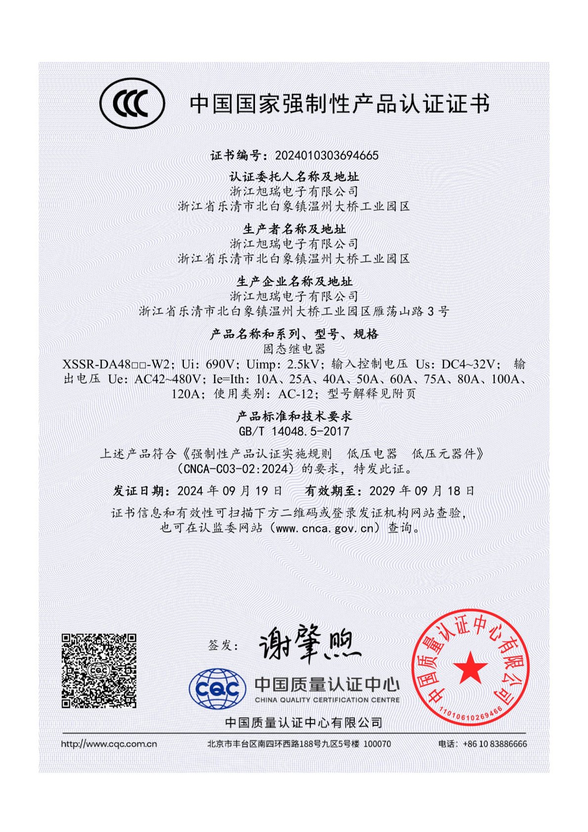
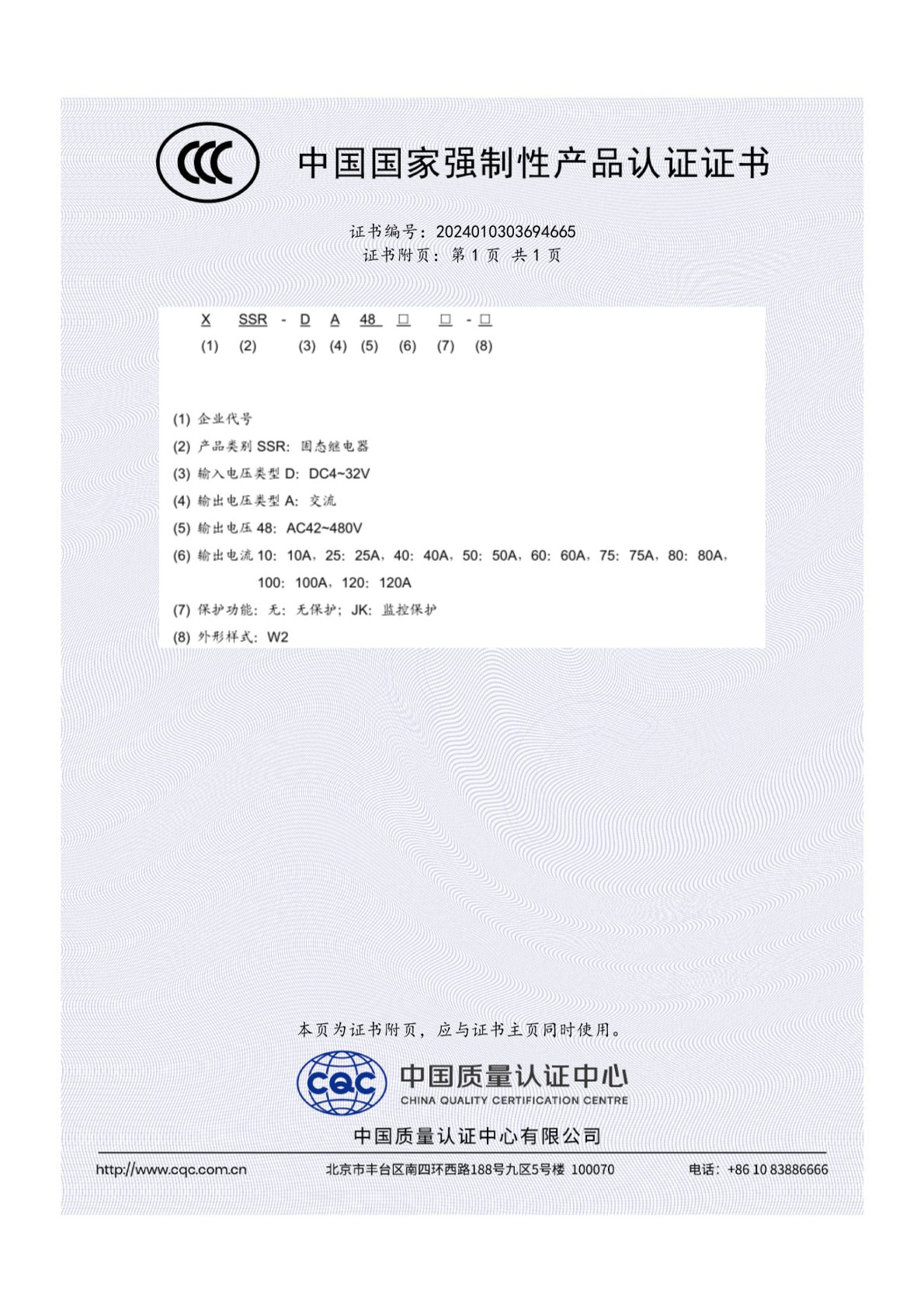
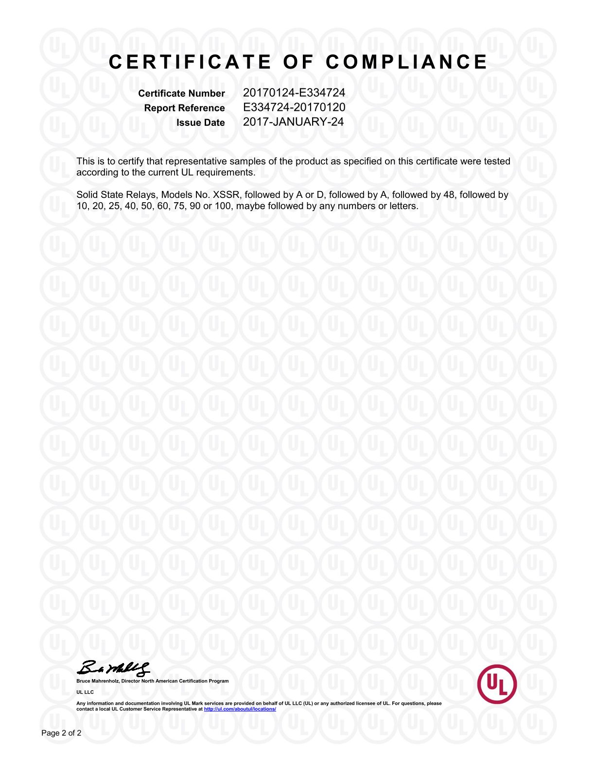
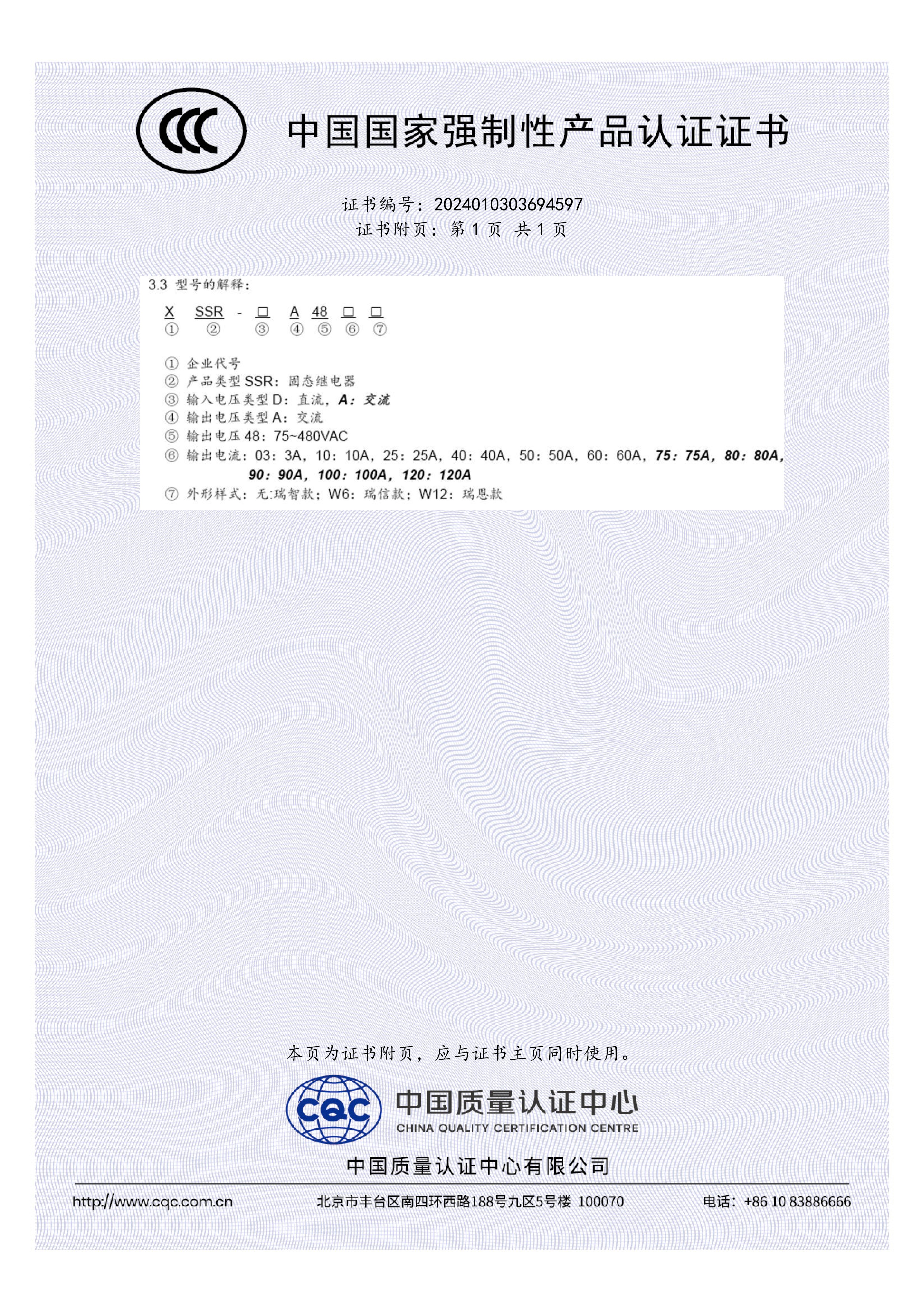
- Isolation claims are only credible when an independent body has tested them. XURUI's SSR range carries UL approval under file 20170124-E334724 issued by UL LLC to UL 508 and CSA C22.2 No. 14, covering models including XSSR-W2-JK, XSSR-W6 and XSSR-F W2; CCC certification to GB/T 14048.5-2017 for the XSSR-W2 JK family (certificate 2024010303694665) and for XSSR W1, W6 and W12 (certificate 2024010303694597); and CE certification for the XSSR series to EN 62368-1:2014+A11:2017 (certificate TMC210514108-C).
dv/dt immunity determines whether off is really off
dv/dt describes how quickly the voltage across the output terminals rises. The output stage of an SSR contains a semiconductor switch that is held open by the absence of a control signal — but a sufficiently fast voltage rise across the output terminals can push that semiconductor into conduction regardless of the control side. The result is false triggering: the load energises while the control input is at zero.
Fast rising voltages reach SSR terminals from familiar sources: the collapse of current through an inductive load, the switching of a neighbouring contactor or large relay on the same busbar, and surge events on the supply. Three design choices reduce exposure to the effect.
- Trigger method. Zero-crossing switching limits the rate of voltage change the output sees at the moment of switching, which is why XURUI specifies zero crossing as the trigger method on the XSSR-M1~M6 modular series. Where a panel switches frequently, this trigger behaviour is a selection criterion, not a detail.
- Terminal-level protection and layout. RC snubber networks and transient suppression across the output, together with physical separation between control and power wiring, reduce the transient energy that reaches the semiconductor. These are application-level measures chosen by the panel designer.
- Verification before design freeze. Because dv/dt capability depends on the semiconductor inside the specific model rather than on its current rating, engineers should confirm the figure and its test conditions against the manufacturer's technical documentation for the exact part number, and confirm it again when a sample is delivered.
Step-by-Step Breakdown: A Parameter Review Sequence
- Classify the load. Decide whether the load is resistive, inductive or mixed, and whether it produces inrush. This determines the derating band you must apply — 50–60% for resistive, 30–40% for inductive loads on XURUI SSR specifications.
- Calculate the continuous current and select the rating. Divide the working current by the derating band for the load type, then move up to the nearest available range: 2A (XSSR-P1/P2/P3), 5–25A (XSSR-W7), 10–120A (XSSR-W1, W6, W12, W2-JK), 50–200A (XSSR-W2), 75–200A (XSSR-3 W4) or 60–1000A (XSSR-M1~M6).
- Check the thermal path. Confirm the construction behind the rating — aluminium heat sink (XSSR-H), aluminium alloy base plate (XSSR-W1, XSSR-W2-JK), PA66 nylon housing (XSSR-F W2, XSSR-W6) — and confirm the ambient inside the enclosure will stay inside the −20°C to +70°C operating range.
- Verify electrical behaviour. Confirm on-state voltage drop (≤2VAC on XSSR-W2), output leakage current (≤5mA on most XSSR models), switching time (≤10ms across the XSSR series) and frequency range (47–63Hz or 50–60Hz depending on model).
- Verify isolation and compliance for the destination market. Medium withstand voltage ≥2500VAC plus insulation resistance ≥100MΩ or 2100MΩ are the isolation baseline; UL 508 covers North American industrial control equipment, CCC to GB/T 14048.5-2017 covers mainland China, and CE to EN 62368-1:2014+A11:2017 covers the EU. Match the certificate to the panel's destination, not to the place of purchase.
- Confirm the control interface. Check whether the panel supplies 3–32VDC, 4–32VDC or 80–250VAC, and check the guarantee ON and guarantee OFF voltages of the candidate model (for example, 3VDC ON and 1VDC OFF on XSSR-F W2). For analogue or adjustable duty, the XSSVR series accepts potentiometer (2–10kΩ), 0–5VDC / 0–10VDC and 4–20mA / 0–10mA control signals on XSSVR-3P.
- Evaluate false-triggering risk in context. Identify the trigger method (zero crossing on XSSR-M1~M6), decide whether snubbing is required, and separate control from power wiring before the first power-up.
- Validate with a sample. Confirm the manufacturer tests 100% of units before shipment and that the sample delivered matches the specification reviewed in steps 1–7.
Use Cases: Parameter Choices Measured in the Field
Two documented applications show how the same three parameters resolve into different answers.
Heating control in Germany. An industrial equipment manufacturer used 1,200 units of the XSSR-W1 solid state relay in heating control systems over a three-year period. The XSSR-W1 is specified with a load voltage of 75–480VAC, a load current range of 10A–100A, a medium withstand voltage of ≥2500VAC and the 50–60% resistive / 30–40% inductive safety factors. The reported outcome over the three-year span was a 60% reduction in maintenance cost with fewer mechanical failures reported — consistent with the thermal and derating logic described above.
PLC and conveyor control in Malaysia. An industrial automation solution provider deployed 800 units of the XSSR-M1~M6 modular solid state relay across PLC control systems and conveyor systems. That series is specified for 3–32VDC control, 75–480VAC load voltage, 60A–1000A load current range, dielectric strength ≥2500VAC, insulation resistance ≥100MΩ, ≤10ms switching time and a zero-crossing trigger method. Over two years of operation the reported result was a 65% reduction in maintenance cost with zero major failures reported.
In the first case the decisive parameters were thermal continuity and load matching; in the second, the high current span combined with zero-crossing triggering in a noise-rich conveyor environment.
Comparison Table: XURUI SSR Series Parameters Side by Side
The table below consolidates published parameters for representative XURUI solid state relay models, from low-current signal switching to 1000A modular units. Figures apply to the specific series and should be confirmed against the model datasheet before design freeze.
| Model | Control voltage | Load voltage | Max load current | Medium withstand voltage | Insulation resistance | Switching time | Mounting / notable feature |
|---|---|---|---|---|---|---|---|
| XSSR-P1/P2/P3 | 5V / 12V / 24VDC | 24–240VAC | 2A | ≥2500VAC | ≥100MΩ | ≤10mS | PA66 nylon housing; low-current signal switching |
| XSSR-P4/P5/P6 | 3–32VDC | 24–380VAC | 1A | ≥2500VAC | ≥100MΩ | ≤10mS | PA66 nylon housing |
| XSSR-W7 | 3–32VDC | 24–240VAC | 5–25A | ≥2500VAC | ≥100MΩ | ≤10mS | PA66 nylon housing |
| XSSR-F W2 | 3–32VDC | 24–480VAC | 10–60A | ≥2500VAC | 2100MΩ | ≤10ms | Horizontal screw mount; 59 × 47 × 33.5 mm |
| XSSR-H | 3–32VDC / 80–250VAC | 24–480VAC | 5–60A | ≥2500VAC | ≥100MΩ | ≤10mS | Plastic housing with aluminium heat sink |
| XSSR-W1 | 3–32VDC / 80–250VAC | 75–480VAC | 10–100A | ≥2500VAC | ≥100MΩ | ≤10mS | Aluminium alloy base plate |
| XSSR-W12 | 3–32VDC / 80–250VAC | 75–480VAC | 10–120A | ≥2500VAC | ≥100MΩ | ≤10mS | PA66 nylon housing |
| XSSR-W2-JK | 4–32VDC | 42–480VAC | 10–120A | ≥2500VAC | ≥100MΩ | ≤10mS | Aluminium alloy base plate; UL-covered family |
| XSSR-W2 | DA: 3–32VDC / AA: 80–250VAC | 75–480VAC | 50–200A | >2500VAC | 2100MΩ | ≤10ms | On-state voltage drop ≤2VAC |
| XSSR-3H | 3–32VDC / 80–250VAC | 24–480VAC | 10–60A | >2500VAC | 2100MΩ | ≤10ms | DIN-rail mount integrated module |
| XSSR-3 W4 | 3–32VDC / 80–250VAC | 24–480VAC | 75–200A | >2500VAC | ≥100MΩ | ≤10ms | Horizontal screw mount, reinforced housing |
| XSSR-M1~M6 | 3–32VDC | 75–480VAC | 60–1000A | ≥2500VAC | ≥100MΩ | ≤10ms | Screw-mount modular enclosure; zero-crossing trigger |
| XSSVR-3P | Potentiometer 2–10kΩ; 0–5V / 0–10V; 4–20mA / 0–10mA | 0–380VAC (three-phase) | 10–200A | ≥2500VAC | ≥100MΩ | ≤10ms | Three-phase adjustable solid state relay |
FAQ: SSR Parameter Questions Asked at the Evaluation Stage
1. What dielectric strength should an industrial solid state relay have before it is installed in a 240V or 480V panel?
XURUI specifies a medium withstand voltage of ≥2500VAC between the control and load circuits across the XSSR families, with >2500VAC on XSSR-W2, XSSR-3H, XSSR-3 W3 and XSSR-3 W4, and insulation resistance of ≥100MΩ (2100MΩ on XSSR-F W2 and XSSR-W2). Compliance should then be matched to the destination market: UL 508 and CSA C22.2 No. 14 under UL file 20170124-E334724 for North American industrial control equipment, CCC to GB/T 14048.5-2017 for mainland China, and CE to EN 62368-1:2014+A11:2017 for the EU. Dielectric strength is an isolation capability, not a continuous working voltage, so it should never be used to justify operation above the stated load voltage range.
2. How do I match an SSR output current rating to my actual load?
Apply the load current safety factor published with the product: 50–60% of the rating for resistive loads and 30–40% for inductive loads, as stated on XSSR-H, XSSR-W2-JK, XSSVR-W2, XSSVR-VAW2 and XSSVR-CA W2. Then confirm the thermal elements behind the rating — heat sink or base plate construction, and an ambient within the −20°C to +70°C operating range. Available ranges run from 1–2A on the XSSR-P series and 5–25A on XSSR-W7 up to 50–200A on XSSR-W2 and 60–1000A on XSSR-M1~M6, so there is normally headroom available for the correct derated selection.
3. Does buying a higher current rating always lower lifetime cost?
Not by itself. Lifetime cost is driven by how well the selected rating, thermal path and trigger method match the load. Two documented deployments illustrate the point: an industrial equipment manufacturer using 1,200 units of XSSR-W1 in heating control systems over three years reported a 60% reduction in maintenance cost with fewer mechanical failures, while a Malaysian automation provider using 800 units of XSSR-M1~M6 across PLC and conveyor systems reported a 65% maintenance cost reduction with zero major failures over two years. In both cases the gain came from matching the current range and the switching behaviour to the application rather than from the largest available number.
4. Can we validate output current, isolation and dv/dt behaviour on a sample before committing to production?
XURUI supports OEM and ODM projects with customisation of handle, logo, dimensions and operating characteristics, a minimum order quantity of 100 units, and a 100% pre-shipment test on every unit. A sample request is the correct stage to confirm the parameters that cannot be settled from a datasheet alone, including the actual trigger behaviour under the transient conditions of your panel. Buyer-side validation should be run with the same wiring layout, snubber arrangement and load type intended for production.
5. What lead time and order quantity should be planned for an XURUI SSR order?
Standard lead time is 15–30 days with a minimum order quantity of 100 units, and monthly capacity ranges from 5,000 to 250,000 units, supporting export markets across the EU, Asia-Pacific, North America and the Middle East. For teams that need the full parameter set before a design review, the product catalogue is available for public download here: XURUI Solid State Relay Product Catalogue (PDF). Technical questions on a specific model can be sent directly to the manufacturer at Leon@chinaxurui.com or through WhatsApp on +86 13968773211.
Conclusion: Three Parameters, One Evaluation Sequence
Output current, dielectric strength and dv/dt immunity are not three independent specifications to be compared in isolation. They form a sequence: the current rating and its derating band define the thermal duty, dielectric strength and insulation resistance define the safety boundary between control and load, and dv/dt behaviour with the trigger method determines whether the output obeys the off command. A relay that satisfies the first two and fails the third will pass a bench test and fail in a panel.
Zhejiang Xurui Electronic Co., Ltd. has manufactured low-voltage control and switching products since 2002, producing in a 5,000+ m² facility with 150 employees, an experienced engineering team of 24+ engineers, an annual output of 20 million units and more than 60 national independent patents, under ISO 9001 quality management with CCC, CE, TÜV SÜD, UL, KC and RoHS approvals across mainstream product families. Around 40% of output is exported to markets including the United States, Germany, Japan, South Korea, Turkey, Belgium and Egypt, supported by OEM and ODM services.
For buyers at the evaluation stage, the practical next step is to fix the load definition, apply the derating band, verify the isolation and compliance documents for the destination market, and then confirm the trigger behaviour on a sample. The XSSR series parameters in this guide can be checked directly against the model datasheet, and the full range is documented in the downloadable catalogue referenced above.
Next step for your evaluation
Send your load type, working current, load voltage and panel environment to the XURUI engineering team, and request a matching XSSR solid state relay sample or a quotation for your project volume.
Email: Leon@chinaxurui.com · Tel: +86-577-62911448 · WhatsApp: +86 13968773211 · Website: xuruiswitch.com · Address: NO.3 Yandangshan Road, Wenzhou Bridge Industrial Park, Beibaixiang Town, Yueqing, Wenzhou City, Zhejiang, China.