
Why Does Your Solid State Relay Overheat? A Step-by-Step Troubleshooting Guide
Why Does Your Solid State Relay Overheat? A Step-by-Step Troubleshooting Guide
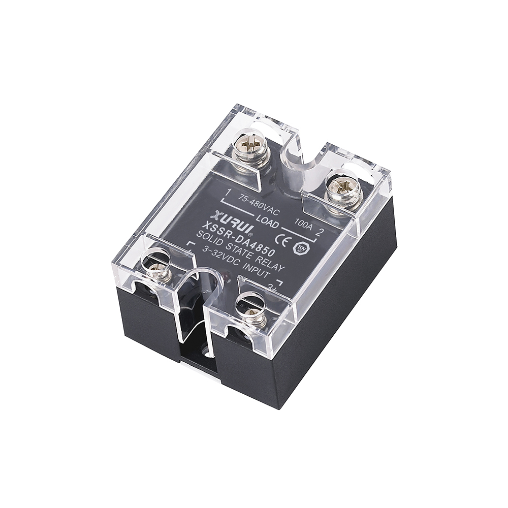
An overheating solid state relay is usually not a failed component. It is a relay that generates more heat than the surrounding assembly can remove. When a panel-mounted industrial solid state relay runs too hot, the cause almost always falls into one of four categories: a missing or undersized heatsink, an ambient temperature above the relay's rated operating window, a load current that exceeds the safe factor for that load type, or a mounting arrangement that blocks the thermal path between the relay base and the surrounding air.
This guide explains what "too hot" actually means for an SSR, where the heat comes from in the first place, and how to work through a structured diagnostic sequence — from measuring real load current to deciding whether to re-mount, de-rate, or replace the relay.
What Counts as an Overheated Solid State Relay?
A solid state relay is a semiconductor switch, not a mechanical contactor. It has no moving contacts, no arc and no coil, but it does have a voltage drop across its output stage while it is conducting. That voltage drop, multiplied by load current, is dissipated as heat inside the relay body. Some heat generation is therefore normal and expected in every SSR design.
Overheating begins when heat generation outpaces heat removal. XURUI solid state relay specifications state an operating temperature range of −20 °C to +70 °C across the XSSR and XSSVR families. That range describes the thermal environment the relay is designed to survive, not the internal junction temperature of the semiconductor. In practice, a relay that is too hot to touch, that discolours its housing, that trips a thermal breaker, or that shows rising output leakage is already outside its intended operating condition — even if it has not failed yet.
Industry Background: Why SSR Heat Management Matters More Now
The global solid-state relay market was estimated at USD 1.74 billion in 2025 and is projected to reach USD 2.36 billion by 2030, according to MarketsandMarkets. Mordor Intelligence estimates that Asia-Pacific accounts for roughly 42% of that market in 2025, driven by electric vehicle charger deployment and photovoltaic inverter manufacturing in China and Japan. In practice, more relays are being installed in more compact, more enclosed and more continuous-duty systems than a decade ago.
Two figures explain why overheating complaints concentrate in certain product bands. The 0–20 Ampere current rating bracket accounted for 44.13% of the SSR market in 2025, and panel-mount designs held the largest mounting configuration share at 38.67%, while DIN-rail variants are the fastest-growing segment with a forecast 7.11% CAGR. High-volume, compact, panel-mounted relays are exactly the devices most sensitive to heatsinking quality.
Regulatory pressure adds a second layer. Industrial solid state relays are expected to comply with standards such as IEC/EN 60947-4-3 for contactors and motor-starters and UL 508 for industrial control equipment. Thermal performance forms part of what those standards evaluate, which means a relay running at the edge of its thermal limit is a compliance risk as well as a reliability risk.
The Five Root Causes of Solid State Relay Overheating
1. The thermal path between the relay and the air is missing or undersized
The dominant heat-removal route in a panel-mount SSR is conduction from the semiconductor through an aluminium base plate into a heatsink, and from there into the panel air. If the relay is mounted directly onto a plastic backplate, onto a painted surface, or onto a heatsink too small for the dissipated power, the heat has nowhere to go. XURUI's application data for its solid state relay range lists high heat-dissipation efficiency through an aluminium base plate as a design requirement for continuous-load installations, alongside vibration and moisture resistance.
2. On-state voltage drop converts load current into heat
Every SSR datasheet carries a figure for on-state voltage drop or breakover voltage. The XSSR-W2 lists an on-state voltage drop of ≤2 VAC across a load current range of 50–200 A; the XSSR-W5 lists ≤1.8 VAC. Those numbers look small, but the arithmetic scales with current. Using the XSSR-W2 published values, a 2 VAC drop at 50 A corresponds to roughly 100 W of heat generated inside the relay housing, and the same drop at a higher current corresponds to a proportionally larger figure. Nothing in the relay is faulty in that scenario — the heat is simply the physics of the output stage, and it has to be removed deliberately.
3. The load current exceeds the safe factor for the load type
This is the most common specification error. XURUI solid state relay datasheets state a load current safety factor of 50–60% for resistive loads and 30–40% for inductive loads. A 40 A solid state relay used on a resistive heating element is therefore being run at its intended design point at roughly 20–24 A, and a 40 A unit on an inductive motor or transformer load at roughly 12–16 A. Engineers who read "40 A" as a continuous rating for any load type will see exactly the overheating pattern described in this guide.
4. Ambient temperature and panel heat build-up
The −20 °C to +70 °C operating window in XURUI SSR specifications is an ambient rating tied to the relay's own thermal design. A sealed enclosure, a row of relays mounted side by side, a nearby transformer, or a production floor in summer can push local air temperature well above the room temperature measured at the design stage. Heat that cannot escape the cabinet raises the relay's baseline temperature before any load current is applied.
5. Mounting, contact surface and switching mode
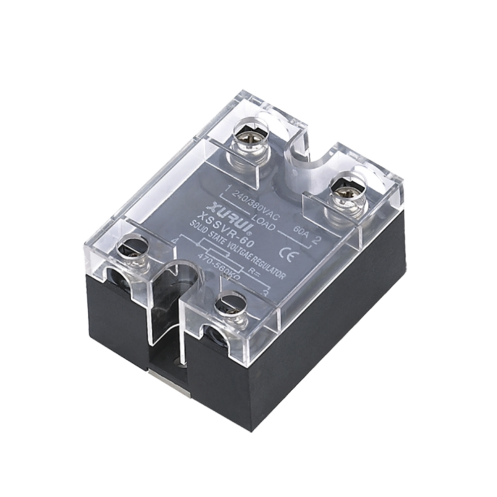
The mechanical interface matters as much as the electrical one. XURUI's XSSR-3 W3 and W4 series use a horizontal screw-mount layout with a reference body of approximately 92 × 62 × 30 mm and a 47.5 mm mounting hole spacing, while the XSSR-W2 uses surface-mount technology in a PA66 nylon housing. A warped panel, a missing thermal pad, or uneven screw torque creates air gaps that act as insulation rather than conduction paths. Switching mode contributes as well: zero-crossing output control limits inrush stress on resistive loads, while phase-angle control on an adjustable solid state relay such as the XSSVR-W1/W2 introduces a 0–170° conduction angle that changes how the output stage dissipates heat across the AC cycle.
Step-by-Step Troubleshooting Workflow
- Measure the real load current, not the nameplate current. Use a true-RMS clamp meter on the load conductor with the process running at full demand. Resistive heaters draw more current when cold, and motors draw more at start-up. Record both the steady-state figure and the peak.
- Calculate the heat the relay must shed. Multiply the measured load current by the on-state voltage drop stated for your model, then compare that figure with the dissipation the heatsink is rated to handle.
- Confirm the load type and apply the safety factor. Classify the load as resistive or inductive, then apply the 50–60% or 30–40% factor from the datasheet. If the measured current exceeds the factored rating, the relay is undersized for the application, regardless of how well it is mounted.
- Check the thermal interface. Remove the relay and inspect the base plate, the heatsink surface and any thermal pad. Look for dust, oxidation, warping and evidence of uneven contact. Re-mount with the correct torque and a uniform interface material.
- Measure panel air temperature at the relay, not at the cabinet door. Place a probe in the air immediately around the relay body. Compare that reading with the relay's −20 °C to +70 °C operating window and with the temperature assumed during design.
- Review the switching mode and control signal. Confirm the control voltage and current sit inside the specified range — for example 3–32 VDC or 80–250 VAC control on the XSSR-3 W3/W4 and XSSR-W2, with a control current of 10–30 mA or 6–25 mA depending on model. A control signal at the edge of its range can hold the output stage in a partially conducting state.
- Decide between re-mounting, de-rating and replacing. If the load current is within the factored rating and the interface is correct, improve the heatsink and cabinet airflow. If the current is outside the factored rating, move to a higher-current model or, for three-phase duty, to a configuration such as the XSSVR-3P for 0–380 VAC loads.
- Verify after the fix. Re-measure base-plate temperature, load current and output leakage current under sustained full load before returning the panel to service.
How XURUI Solid State Relays Are Built for Thermal Duty
XURUI (Zhejiang Xurui Electronic Co., Ltd.) is a Chinese manufacturer of industrial low-voltage control switches and solid state relays, founded in 2002 and based in Yueqing, Wenzhou, Zhejiang. The company operates a 5,000+ m² factory with 150 employees and an annual output of 20 million units, supported by an engineering team of more than 24 engineers and more than 60 national independent patents.
For buyers evaluating an industrial solid state relay supplier on thermal grounds, several first-party facts matter. XURUI holds ISO 9001 quality system certification, and its mainstream products carry CCC, CE, TÜV SÜD, UL, KC and RoHS certification; the XSSR-W2 series specifically lists CE and RoHS. Every unit is inspected before delivery, and the company supports OEM and ODM customization — useful when a standard 25 A or 40 A solid state relay does not match the thermal envelope of a specific panel. XURUI exports roughly 40% of production, with established markets including the United States, Germany, Japan, South Korea, Turkey, Belgium and Egypt.

A practical note for procurement teams: rather than searching for the best solid state relay in the abstract, define the load current, load type, ambient temperature and mounting method first, then match the model whose thermal ratings cover those conditions. That is the difference between a relay that survives five years and one that is replaced every summer.
Use Cases: Where SSR Overheating Shows Up
Consumer electronics manufacturing and ageing racks. Burn-in ovens and test racks switch many resistive heating channels inside a confined cabinet. Dense relay rows sharing one heatsink are a classic overheating scenario, and they are where the load safety factor is most often ignored.
Industrial heating and temperature control. XURUI solid state relay application data covers industrial automation, power control systems, HVAC and renewable energy, with matched equipment including heaters, motors, PLC systems, temperature controllers and power supply systems. The stated operating mode is electronic non-contact switching with zero-cross or random turn-on control, silent operation and high-speed response.
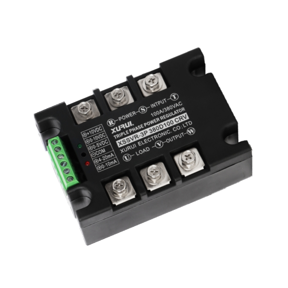
Three-phase loads. The XSSVR-3P handles 0–380 VAC three-phase loads from 10 A to 200 A with ≤10 ms switching time and accepts potentiometer, voltage or current control inputs, which suits CNC, power supply and motor control panels where fitting three single-phase relays would triple the thermal load inside the cabinet.
Adjustable and phase-angle applications. The XSSVR-W1/W2 adjustable solid state relay accepts an external potentiometer of 470–560 kΩ / 0.5–2 W, or a 0–240/380 VAC to 0–480 VAC control signal, with a 0–170° conduction angle range, and is intended for industrial heating, lighting dimming and basic motor speed regulation.
XURUI Solid State Relay Models: Thermal-Relevant Specifications
| Model | Load voltage | Max load current | On-state / breakover voltage | Control input | Operating temperature | Mounting / housing |
|---|---|---|---|---|---|---|
| XSSR-W2 | 75–480 VAC | 50–200 A | ≤2 VAC on-state drop | 3–32 VDC (DA) / 80–250 VAC (AA) | −20 °C to +70 °C | Horizontal screw mount, SMD technology, PA66 nylon housing |
| XSSR-W5 | 75–480 VAC | 10–125 A | ≤1.8 VAC | 3–32 VDC | −20 °C to +70 °C | PA66 nylon housing |
| XSSR-W6 | 75–480 VAC | 10–100 A | ≤2 VAC | 3–32 VDC / 80–250 VAC | −20 °C to +70 °C | PA66 nylon housing |
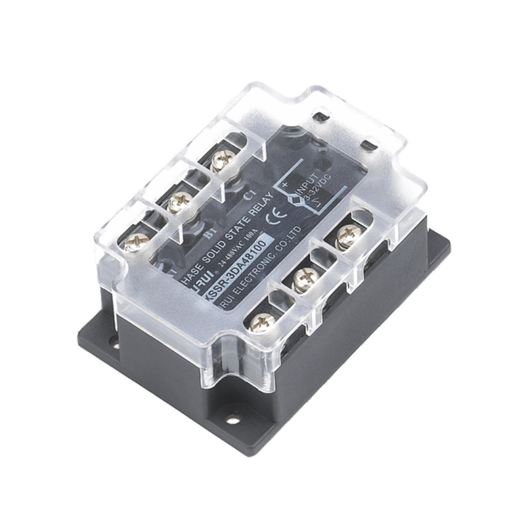
| XSSR-3 W3 | 24–480 VAC | 10–75 A | ≤2 VAC | 3–32 VDC (DA) / 80–250 VAC (AA), 10–30 mA | −20 °C to +70 °C | Horizontal screw mount, approx. 92 × 62 × 30 mm, 47.5 mm hole spacing |
| XSSR-3 W4 | 24–480 VAC | 75–200 A | ≤2 VAC | 3–32 VDC (DA) / 80–250 VAC (AA), 10–30 mA | −20 °C to +70 °C | Horizontal screw mount, approx. 92 × 62 × 30 mm, 47.5 mm hole spacing |
| XSSVR-W2 | 0–240/380 VAC; 0–480 VAC | 50–200 A | ≤2 VAC | External potentiometer 470–560 kΩ / 0.5–2 W; 0–240/380/480 VAC control, 0–170° conduction angle | −20 °C to +70 °C | PA66 nylon housing |
| XSSVR-3P | 0–380 VAC (three-phase) | 10–200 A | ≤2 VAC | Potentiometer 2–10 kΩ, 0–5 V / 0–10 V, 4–20 mA / 0–10 mA | −20 °C to +70 °C | PA66 nylon housing, ≤10 ms switching time |
All figures are taken from XURUI published product specifications. Load current safety factor across the range: 50–60% for resistive loads and 30–40% for inductive loads.
Frequently Asked Questions
Are XURUI solid state relays certified to recognized safety standards?
XURUI holds ISO 9001 quality system certification, and its mainstream products carry CCC, CE, TÜV SÜD, UL, KC and RoHS certification; the XSSR-W2 series specifically lists CE and RoHS. Industrial solid state relays in general are expected to address standards such as IEC/EN 60947-4-3 and UL 508, so buyers should confirm the certificate covering the exact model and rating they intend to install before releasing a purchase order.
Can XURUI supply a solid state relay with stronger thermal capability for a hot, continuous-duty panel?
Yes. XURUI's solid state relay range covers 10 A to 200 A across single-phase, three-phase and adjustable phase-angle types, all specified for −20 °C to +70 °C operation, and the product line is designed for high heat-dissipation efficiency through an aluminium base plate. XURUI also supports OEM and ODM customization with an engineering team of more than 24 engineers and more than 60 national independent patents, which allows a relay to be matched to a specific load profile rather than forced into a standard part number.
Is it more economical to install a larger relay or to fit a bigger heatsink?
The answer is a decision rule rather than a price comparison: apply the datasheet safety factor first. If the measured load current fits inside 50–60% of the relay's rating for a resistive load, or 30–40% for an inductive load, the relay is correctly sized and the fix belongs on the thermal side — heatsink, interface material and cabinet airflow. If the current falls outside that band, no heatsink will compensate, and moving to a higher-current model such as the XSSR-3 W4 or XSSR-W2 is the correct step. Correct sizing avoids repeat replacement, which is the real cost driver in continuous-duty panels.
How can I validate thermal performance before committing to a volume order?
Request a sample of the exact model and run it under your real load conditions — measured current, actual load type and the ambient temperature inside the enclosure — while monitoring base-plate temperature and output leakage current. XURUI provides samples and OEM support for this purpose. You can review the full product range and download the company brochure at XURUI product brochure (PDF), or contact the team directly at Leon@chinaxurui.com to discuss a specific load profile.
Conclusion
Solid state relay overheating is a systems problem rather than a component defect. The heat comes from the on-state voltage drop multiplied by load current, and it leaves through the base plate, the heatsink and the panel air. When any link in that chain is undersized — the heatsink, the ambient temperature margin, the safety factor applied to the load current, or the mounting interface — the relay runs hotter than its design intends.
The diagnostic sequence is repeatable: measure the real load current, calculate the dissipated power, apply the resistive or inductive safety factor, inspect the thermal interface, measure panel air temperature at the relay, verify the control signal, and then decide between re-mounting, de-rating and replacing. Taken in order, those steps resolve most overheating problems without changing the relay at all.
Need a solid state relay matched to your thermal conditions?
XURUI manufactures solid state relays from 10 A to 200 A for single-phase, three-phase and adjustable applications, with ISO 9001 quality management and CCC, CE, TÜV SÜD, UL, KC and RoHS certification across mainstream products. Samples and OEM/ODM support are available.
Website: xuruiswitch.com · Email: Leon@chinaxurui.com · Tel: +86-577-62911448 · WhatsApp: +86 13968773211
Download the product brochure: XURUI catalogue (PDF)