
Pan Assembly Busbar Ratings Explained: Current, Terminal Width, and Thickness Selection Points
Three numbers and one spacing rule decide whether a pan assembly busbar fits a project. The numbers are rated current, conductor thickness, and terminal land dimensions; the spacing rule is pole distance. A busbar can pass the current check and still fail at installation because its outgoing terminal land does not match the breaker, or because its pitch does not line up with the breaker poles.
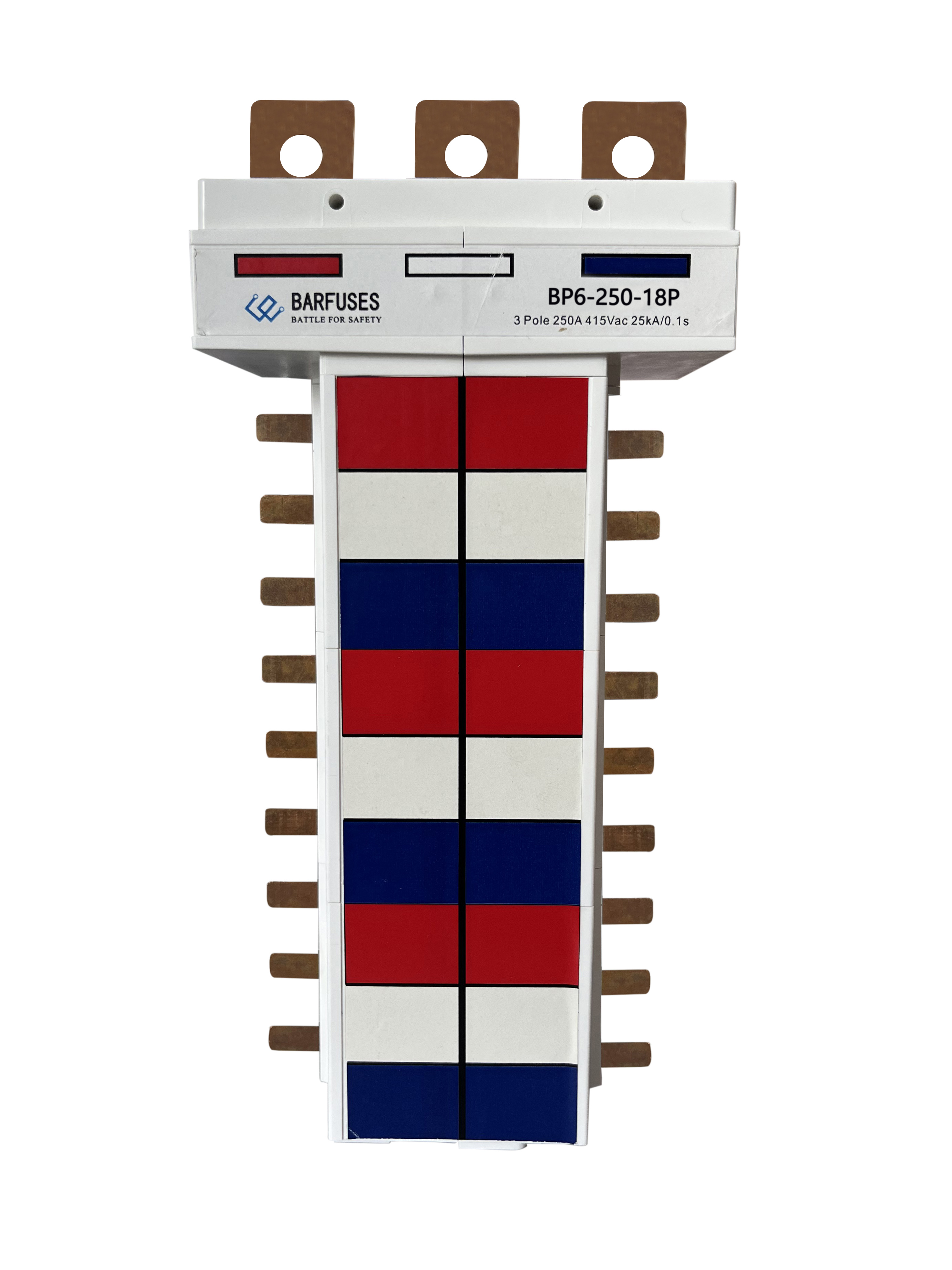
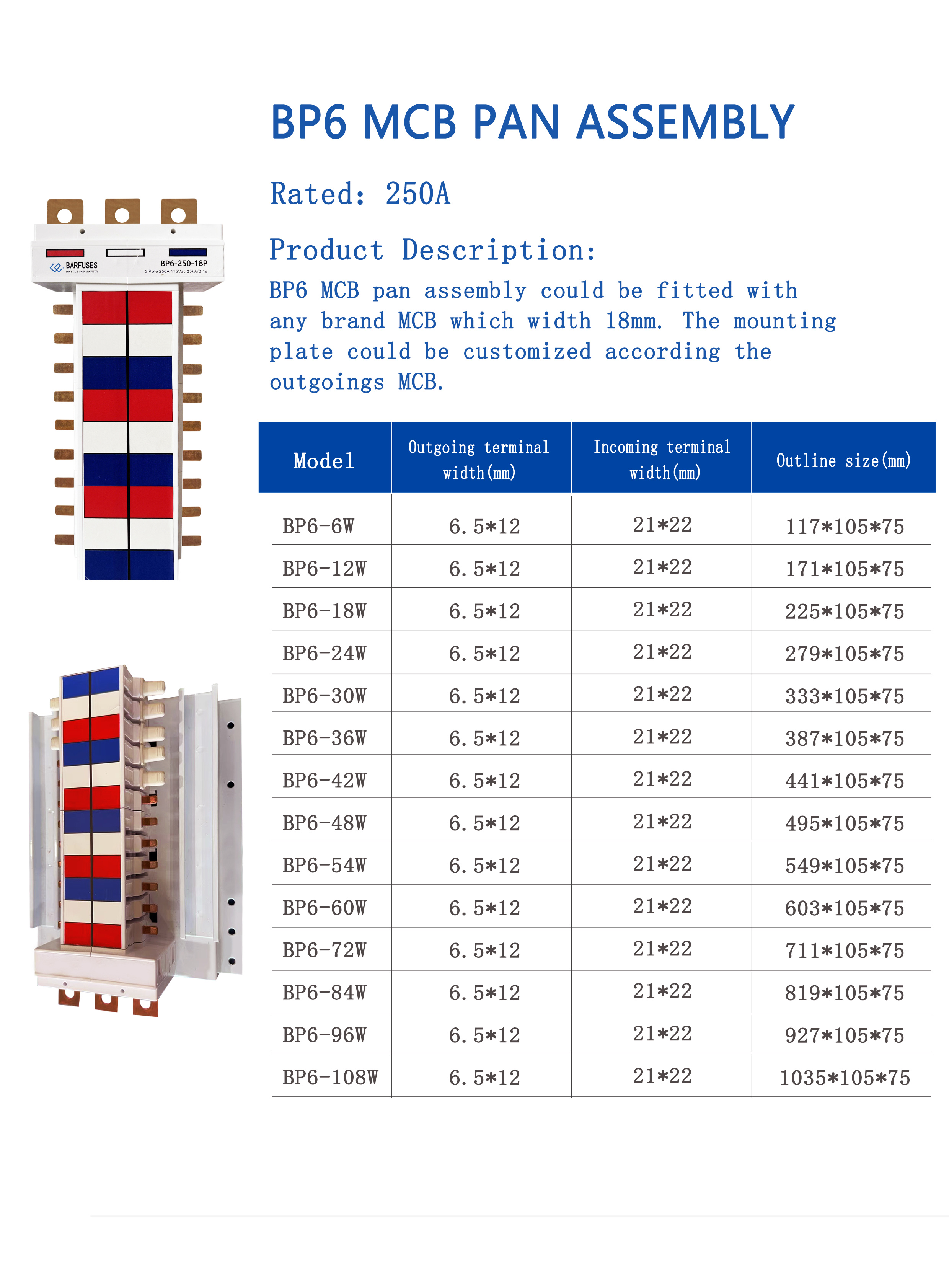
Barfuses (YUEQING BARFUSE ELECTRIC CO.,LTD) is a manufacturer based in Yueqing, Zhejiang Province, China, producing low voltage fuse switch disconnectors, busbar systems and high & low voltage distribution wiring management products, including MCB pan assemblies and MCCB pan assemblies. Two models from that range show how far the parameters are fixed at model level rather than left to the installer. The BP6 MCB 3P chassis busbar is rated 250A with an outgoing terminal width of 6.5 × 12 mm and an incoming terminal width of 21 × 22 mm. The BP5 MCCB 2P pan assembly busbar uses a rated conductor thickness of 2 mm at 63A and 3 mm at 125A on the outgoing side, and 4 mm at 125A, 6 mm at 250A and 10 mm at 400A on the incoming side.
This guide works through each parameter in the order a buyer meets it — rated current, conductor thickness, terminal width, pole distance, ways and enclosure — and marks the points at which a specification decision is locked in and cannot be corrected later in the project.
Problem Definition: Why Pan Assembly Busbars Are Specified Incorrectly
Most pan assembly busbar mismatches are not electrical. They are dimensional. The bar carries the load it was rated for, but one of four interfaces does not line up, and the error is only discovered when the breakers are fitted.
- Terminal land mismatch. The outgoing terminal width is too narrow or too wide for the device terminal it must feed, so the joint cannot seat flat across its full contact area.
- Thickness mismatch. A bar selected on current rating but at the wrong thickness step. Within the BP5 family alone, rated thickness runs from 2 mm at 63A up to 10 mm at 400A.
- Pole distance mismatch. The breaker family's poles sit at 25 mm, 30 mm, 35 mm or 45 mm while the busbar pitch is cut for a different spacing.
- Ways and enclosure mismatch. A ways count that exceeds the usable width of the enclosure, or a mounting plate that cannot be adapted to the outgoing MCB.
The consequence is rarely an immediate failure. In low voltage distribution systems operating continuously, a joint that does not seat flatly increases contact resistance, and a bar mechanically forced into position pre-loads the connection. The visible effects are heat, intermittent nuisance tripping, and installation time lost to field modification rather than a designed-in fit.
Decision rule: confirm the mechanical interface first — terminal land and pole distance — then confirm the electrical rating. Ratings are published in tables; interfaces are not.
Industry Background: Supply and Standards Context
Busbars are a large and still expanding component category, and the material mix is shifting. Precedence Research valued the global busbar market at USD 19.83 billion in 2025, and the same source reports that copper busbars held 62.8% of market share by material in 2025, while aluminium busbars are forecast to grow at a 6.9% CAGR between 2026 and 2035. That aluminium growth is driven mainly by weight and cost optimisation in large infrastructure rather than by a conductivity requirement.
Manufacturing capacity is concentrated. Congruence Market Insights notes that China accounts for over 30% of global copper processing capacity, which is one reason modular pan assembly busbars produced in China are widely supplied to the Middle East, Russia, Latin America, Central Asia, the EU, Africa and Oceania.
On the standards side, the IEC 61439 series is the reference framework for low-voltage switchgear and controlgear assemblies. IEC 61439-6:2025, with an effective date of 1 December 2025, covers busbar trunking systems specifically. It does not by itself define modular pan assembly busbars, because those are supplied as components inside an assembly rather than as a trunking system. Compliance statements should therefore be read at the level at which they are made: the BP6 MCB 3P chassis busbar is stated by the manufacturer to comply with IEC 61439 and AS/NZS standards, and the BP1 MCB 3P pan assembly carries a DEKRA test certificate.
In application terms, these components are used indoors in industrial application and commercial building electric management, matched to circuit breakers, with available current ratings of 125A, 160A, 250A, 400A, 630A and 800A. Their function is power distribution and circuit protection, and the operating mode assumed in specification is continuous.
Detailed Solution: The Parameters That Must Match
1. Rated current: a ceiling, not a target
Rated current defines the maximum the assembly is designed to carry, and it applies separately to the incoming and outgoing sides. Available ratings across the Barfuses pan assembly range include 125A, 160A, 250A, 400A, 630A and 800A.
The MCCB 3P Pan Assembly BP3 is specified with incoming ratings of 250A, 400A, 630A and 800A and outgoing ratings of 125A, 250A and 400A. The MCCB 2P Pan Assembly busbar BP5 splits lower: incoming 125A, 250A and 400A, with outgoing branches at 63A and 125A. On the MCB side, BP1 and BP4 are rated 125A, 160A and 250A, BP2 is rated 125A and 250A, and the BP6 MCB 3P chassis busbar is rated 250A.
The selection error here is treating the highest number as the target. The incoming rating must cover the upstream device, and every outgoing branch rating must sit at or below the incoming rating. A 800A incoming assembly with 125A branches is a valid configuration; the reverse is not.
2. Conductor thickness (T): the current-density decision
Thickness is the parameter buyers most often confuse with current rating, because inside one model family the two move together. In the BP5 MCCB 2P pan assembly busbar, rated thickness is published against each current step: 63A at T 2 mm and 125A at T 3 mm on the outgoing side, and 125A at T 4 mm, 250A at T 6 mm and 400A at T 10 mm on the incoming side.
Two consequences follow from that table. First, the incoming and outgoing conductors of the same assembly can have different thicknesses — a 10 mm incoming bar feeding 2 mm outgoing bars is a normal design, not a compromise. Second, thickness steps are not always large: the BP4 MCB 1P pan assembly busbar is rated 125A at T 2 mm, 160A at T 2.5 mm and 250A at T 3 mm, so a 0.5 mm change in conductor thickness corresponds to a rating step inside the same series.
Thickness is also separate from footprint. The BP1 MCB 3P Pan Assembly is published with a connect size of 2.0 × 5 mm and an outline size of 2.0 × 20 mm — the thickness stays at 2.0 mm while the width changes to serve a different interface. Specifying by overall bar width alone will not capture the thickness requirement.
3. Terminal width: the land the device actually clamps
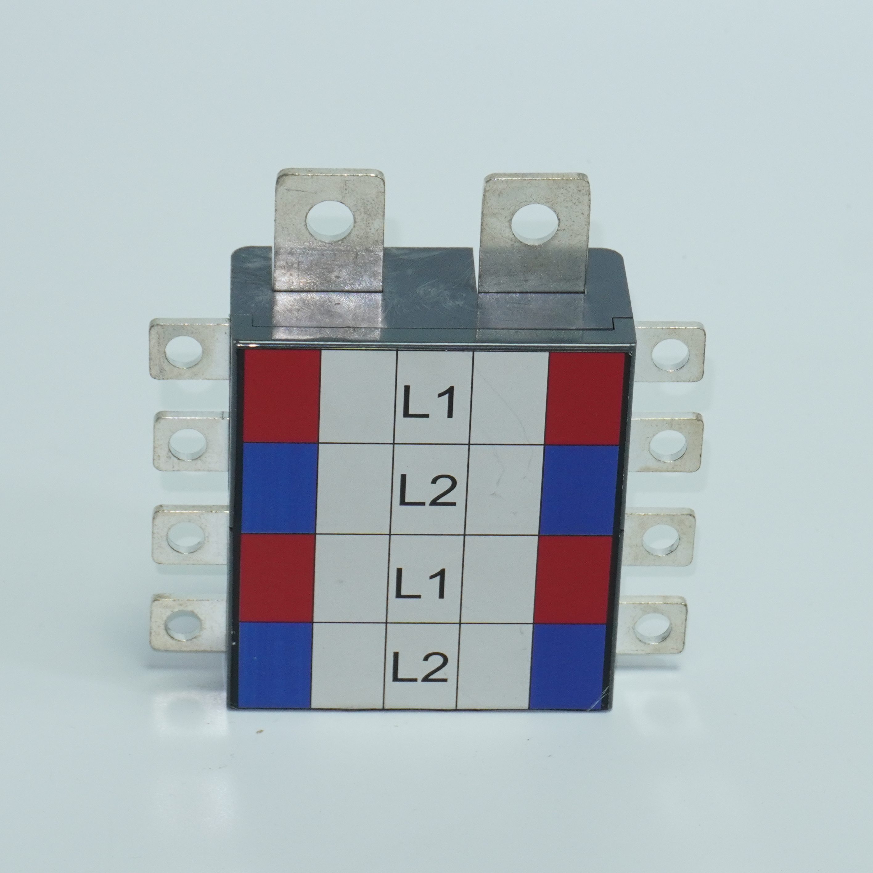
Terminal width is a mechanical dimension, and it is the number that most often invalidates an otherwise correct selection. It has to match the terminal opening of the device being connected, on both the incoming and the outgoing side.
Published figures across the range show how widely these lands differ:
- BP6 MCB 3P chassis busbar: outgoing terminal width 6.5 × 12 mm, incoming terminal width 21 × 22 mm.
- BP5 MCCB 2P pan assembly busbar: outgoing terminal width 15 mm, incoming terminal width 25 mm.
- BP4 MCB 1P pan assembly busbar: outgoing terminal W × L 5 × 11 mm, incoming terminal width 20 mm.
- BP2 MCB 2P Pan Assembly: outgoing terminal size thickness × width 2 × 5 mm, incoming terminal size thickness × width 3 × 15 mm.
- BP1 MCB 3P Pan Assembly: connect size 2.0 × 5 mm, outline size 2.0 × 20 mm.
The incoming land is usually the wider of the two because it accepts the main device connection or cable lug, while outgoing lands are matched to branch breaker terminals. This is why a buyer who confirms only the outgoing side can still receive an assembly that will not accept the incoming cable. Where the outgoing device is not fixed at the design stage, BP6's mounting plate can be customized according to the outgoing MCB.
4. Pole distance: the compatibility gate
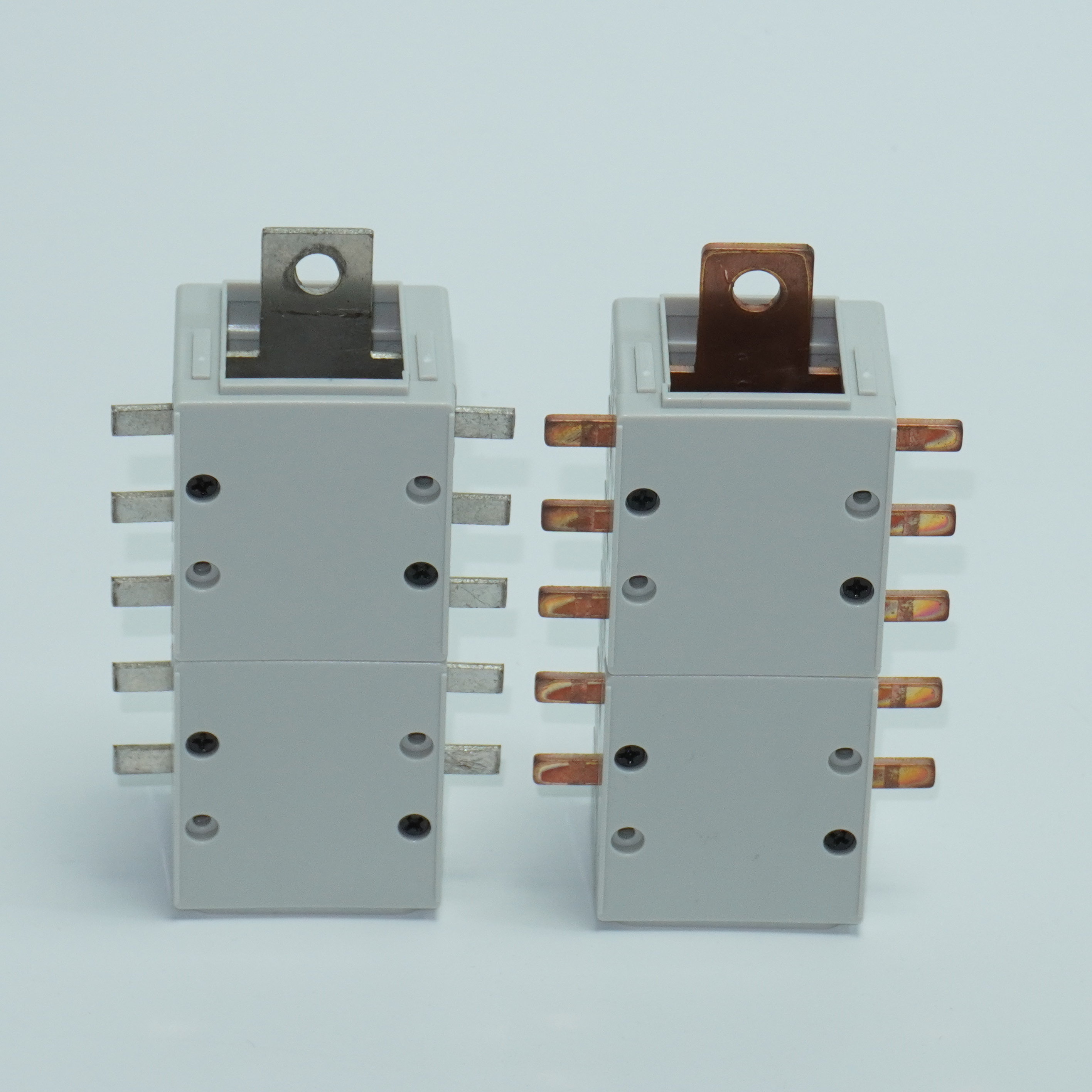
Pole distance determines whether the breakers physically sit on the busbar at all, and it is decided by the breaker family — not by the busbar buyer's preference. The MCCB 3P Pan Assembly BP3 is designed for use with different brand MCCB with pole distance 25 mm, 30 mm, 35 mm or 45 mm. On the BP5 MCCB 2P pan assembly busbar, the DP assembly is intended for branch DP MCCB with 25 mm pole distance and 50 mm width.
Because the pitch is set by the breaker, the correct sequence is to select the breaker first and the busbar second. Once the pole distance is fixed, the ways count follows from the enclosure width available, and the usable configurations narrow quickly. BP3 offers 2W, 4W, 6W, 8W, 10W, 12W and 14W; BP1 offers 6W to 72W; BP4 offers 4W to 72W; BP5 offers 2W to 40W.
5. Material and case parts: copper conductor in a PC carrier
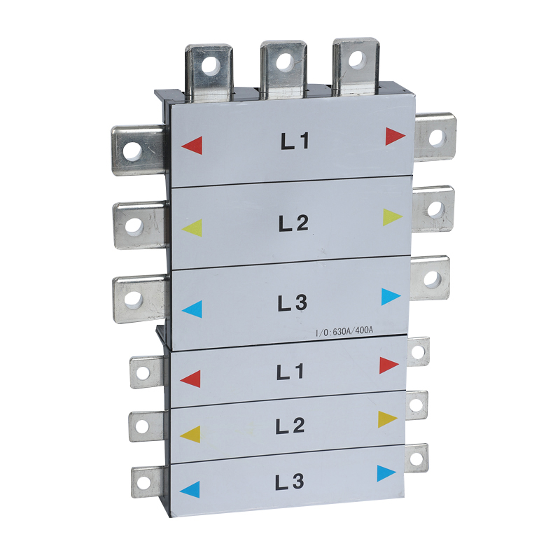
Pan assembly busbars in this range use copper conductors with PC parts as the insulating carrier. The copper carries the current; the PC component holds the pitch and provides the insulation distance between phases. Copper remains the dominant material in the busbar market at 62.8% share by material in 2025, and aluminium alternatives are growing at a 6.9% CAGR forecast for 2026–2035, mainly where weight and cost matter more than conductivity margin. The practical point for a specification is that the conductor material, the thickness and the terminal land must all be confirmed against the same model datasheet — mixing figures from different models produces a specification that does not exist.
Step-by-Step Breakdown: Specifying a Pan Assembly Busbar
The sequence below follows the order in which the constraints actually bind. Changing an earlier step invalidates the later ones, which is why the order matters more than the individual checks.
- Fix the incoming device and its current. Confirm the rating of the upstream breaker or main switch. Available assembly ratings run through 125A, 160A, 250A, 400A, 630A and 800A, so the incoming device establishes which band the assembly starts in.
- Fix the breaker family and its pole distance. Confirm whether the breakers sit at 25 mm, 30 mm, 35 mm or 45 mm pole distance. A model such as BP3 covers all four spacings; BP5's DP configuration is specified for 25 mm pole distance and 50 mm width. Nothing downstream can be selected before this is known.
- Match the outgoing terminal land to the branch breakers. Read the outgoing terminal width from the model table — 6.5 × 12 mm on BP6, 15 mm on BP5, 5 × 11 mm on BP4, 2 × 5 mm on BP2 — and check it against the terminal opening of the branch device.
- Select thickness by current step, incoming and outgoing separately. For BP5 this means 2 mm at 63A and 3 mm at 125A outgoing, and 4 mm at 125A, 6 mm at 250A and 10 mm at 400A incoming. Do not assume one thickness applies to the whole assembly.
- Confirm the incoming terminal land. The incoming land is normally the largest on the assembly — 21 × 22 mm on BP6, 25 mm on BP5, 20 mm on BP4, 3 × 15 mm on BP2. Verify it against the main connection method, including any lug or cable shoe.
- Count ways against the enclosure. Set the number of outgoing ways from the load schedule, then check it against the published range for the model: 2W–14W on BP3, 2W–40W on BP5, 4W–72W on BP4, 6W–72W on BP1. If the ways count approaches the top of the range, confirm the enclosure width at the same time.
- Check the standard and verification level, then validate on a sample. Establish which standard the assembly must meet, confirm what the supplier states, and test the fit with a sample before committing to a production order — particularly when the outgoing device is not yet fixed and the mounting plate must be customized.
Specification checklist: incoming rating → pole distance → outgoing terminal land → outgoing thickness → incoming terminal land → incoming thickness → ways count → enclosure width → standard and verification → sample confirmation.
Use Cases: Where the Parameter Set Changes
Commercial building distribution boards
In commercial building electric management, the typical need is a high incoming rating with many low-current branches. The DB01 distribution box with MCB pan assembly busbar is configured with an incomer of MCCB 250A, MCCB 125A or MCB 63A, MCB branches, and 2W to 32W. Here the selection emphasis sits on the outgoing terminal land and the ways count, because the branch breakers are numerous and identical. A fit error on the outgoing land repeats across every way in the board.
Industrial MCCB distribution
Where branches are also MCCB, currents are higher and thickness becomes the binding constraint. The DB02 distribution box with MCCB pan assembly busbar is configured with an incomer of MCCB 800A / 630A / 400A / 250A / 125A, branch MCCB at 400A / 250A / 125A, and 2W to 16W. In this configuration the incoming conductor can be specified at the top of the thickness scale while outgoing branches sit lower, and pole distance must be confirmed for both the incomer and the branch devices.
Service environments with moisture or dust
Some projects place distribution equipment where enclosure protection, not busbar geometry, is the deciding factor. The DB13 waterproof low-voltage distribution box is rated IP65 with IK10 impact resistance, built from steel sheet with a 1.2 mm–1.5 mm enclosure and door and a 2.0 mm mounting plate. The busbar inside still follows the same parameter logic, but the enclosure constrains the usable width and therefore the maximum ways count.
High-current incoming with low-current branching
Mixing rating bands inside one assembly is normal and is the case where thickness errors are most likely. A BP5 assembly can carry 400A incoming at T 10 mm and feed 63A branches at T 2 mm. A buyer who specifies a single thickness across the whole assembly will either overspend on the outgoing bars or undersize the incoming bar.

Comparison Table: Parameter Reference Across the Pan Assembly Range
| Model | Type | Rated current | Conductor thickness (T) | Outgoing terminal | Incoming terminal | Ways | Pole distance |
|---|---|---|---|---|---|---|---|
| BP1 | MCB 3P Pan Assembly | 125A, 160A, 250A | 2.0 mm | Connect size 2.0 × 5 mm | Outline size 2.0 × 20 mm | 6W–72W | — |
| BP2 | MCB 2P Pan Assembly | 125A / 250A (rated voltage 220/240/120V) | — | 2 × 5 mm (thickness × width) | 3 × 15 mm (thickness × width) | — | — |
| BP3 | MCCB 3P Pan Assembly | Incoming 250A / 400A / 630A / 800A; outgoing 125A / 250A / 400A | — | — | — | 2W, 4W, 6W, 8W, 10W, 12W, 14W | 25 mm / 30 mm / 35 mm / 45 mm |
| BP4 | MCB 1P Pan Assembly busbar | 125A (T 2 mm), 160A (T 2.5 mm), 250A (T 3 mm) | 2 mm / 2.5 mm / 3 mm | W × L 5 × 11 mm | Width 20 mm | 4W–72W | — |
| BP5 | MCCB 2P Pan Assembly busbar | Incoming 125A / 250A / 400A; outgoing 63A / 125A | Incoming T 4 mm / 6 mm / 10 mm; outgoing T 2 mm / 3 mm | Width 15 mm | Width 25 mm | 2W–40W | 25 mm (DP branch MCCB, width 50 mm) |
| BP6 | MCB 3P chassis busbar | 250A | — | 6.5 × 12 mm | 21 × 22 mm | — | — |
Figures are the manufacturer's published parameters for each model. “—” indicates a parameter not published for that model. BP1 terminal figures are published as connect size and outline size. BP6 is stated by the manufacturer to comply with IEC 61439 and AS/NZS standards; BP1 carries a DEKRA test certificate.
FAQ: Pan Assembly Busbar Selection Questions
Which standards apply when specifying a pan assembly busbar?
The IEC 61439 series is the reference framework for low-voltage switchgear and controlgear assemblies, and IEC 61439-6:2025 — effective 1 December 2025 — covers busbar trunking systems specifically. Modular pan assembly busbars are supplied as components inside an assembly rather than as a trunking system, so a compliance statement should be read at the level it is made. In this range, the BP6 MCB 3P chassis busbar is stated by the manufacturer to comply with IEC 61439 and AS/NZS standards, and the BP1 MCB 3P Pan Assembly carries a DEKRA test certificate. The manufacturer operates an ISO 9001 quality system and holds testing accreditations from KEMA (DEKRA) in the Netherlands and VDE in Germany, plus CB certification and SAA certification in Australia.
Can terminal width, conductor thickness and ways count be customized?
Yes. Production modes are OEM and ODM, and customization covers color, logo, material, new design, surface treatment, mold development and packing. Two model-level examples: BP3 accepts OEM and its size can be customized according to the customer's MCCB, and the BP6 mounting plate can be customized according to the outgoing MCB. Monthly capacity is 8,000 pieces, and quality control is 100% test.
What drives the cost of a pan assembly busbar?
Cost is driven mainly by conductor material and conductor mass, since the copper content scales with thickness × width × length × number of ways. That is why a 400A incoming conductor at T 10 mm and a 63A outgoing conductor at T 2 mm in the same BP5 assembly have very different copper content. Ways count multiplies the outgoing conductor and the PC carrier parts, and customization steps such as surface treatment, mold development, logo and packing add cost that is not conductor-related. Copper busbars held 62.8% of market share by material in 2025, while aluminium busbars are forecast to grow at a 6.9% CAGR between 2026 and 2035, reflecting projects where weight and cost are prioritised over conductivity margin.
Can I validate a sample before placing a production order?
Yes. Minimum order quantity is 1 piece, so a single assembly can be ordered for fit validation, and every unit is 100% tested before dispatch. Sample validation is the practical way to confirm the two parameters that tables cannot fully settle: whether the outgoing terminal land seats correctly on the branch breaker, and whether the pole distance matches the breaker family. Remote technical support is available during validation.
What is the lead time and capacity for a customized busbar order?
Lead time is 15–45 days depending on customization scope, with a monthly capacity of 8,000 pieces. Customization that involves mold development or a new design sits at the longer end of that range, while repeat orders against an existing configuration are shorter. To start a specification review, send the incoming rating, pole distance, outgoing terminal land and ways count to the sales team at sales04@barfuses.com, or send a message on WhatsApp at +86 18815184322. The full model range is listed in the downloadable catalogue below.
Conclusion: Selection Points That Decide the Fit
A pan assembly busbar specification succeeds when four parameters are confirmed against the same model datasheet: rated current for the incoming and outgoing sides, conductor thickness at each current step, terminal land dimensions on both sides, and pole distance compatibility with the breaker family. Ways count and enclosure width then settle the final configuration, and the standard or verification level determines what proof the supplier is expected to provide.
The Barfuses range illustrates how these values differ from model to model rather than converging on a single answer. BP6 fixes 250A with a 6.5 × 12 mm outgoing and 21 × 22 mm incoming terminal land. BP5 spreads rated thickness from 2 mm at 63A to 10 mm at 400A across a single assembly. BP3 accepts 25 mm, 30 mm, 35 mm and 45 mm pole distance MCCB, and BP4 steps through 2 mm, 2.5 mm and 3 mm inside one series. BP1 and BP2 cover the 2P and 3P MCB configurations at 125A to 250A.
YUEQING BARFUSE ELECTRIC CO.,LTD was founded in 2014 and operates a 10,000 m² facility in Yueqing, Zhejiang Province, China, with 45 employees, a 7-engineer R&D team and an annual output of 250,000 PCS. The export ratio is 90%, with sales networks in more than 40 countries and regions across the Middle East, Russia, Latin America, Central Asia, the EU, Africa and Oceania. Production uses over 30 sets of modern digital wire-cutting machines and punches, supported by inspection equipment including a Rockwell hardness tester, an electric withstand voltage tester, a spring tester, a salt spray tester, a flame retardant tester and a switch tester.
Next step: confirm the parameters on a real sample
Send the incoming rating, pole distance, outgoing terminal width and required ways count, and Barfuses will confirm the matching model, rated thickness and lead time. Minimum order quantity is 1 piece, every unit is 100% tested, and remote technical support is available through specification and installation.
Download the catalogue: Barfuse Catalogue (PDF)
Website: www.barfuses.com and www.barfuse.com
Email: sales04@barfuses.com · Tel: 0086 577 61666659
Address: No.88, Weishijiu Road, Economic Development Zone, Yueqing, Zhejiang Province, China (PC: 325600)
Have Questions or Need More Details?
Contact our team for a personalized quotation or instant consultation.
Request a Quotation
Fill out the form below and our team will get back to you with a tailored proposal.
WhatsApp Direct Chat
Prefer to chat in real-time? Message us on WhatsApp for instant assistance & quick answers.
- Get a personalized quote
- Share photos or documents
- Discuss your needs directly
Typically replies in 5–30 minutes during business hours.