
Reading Fuse Switch Disconnector Spec Sheets: Ith, Ue, Ui, Uimp Explained
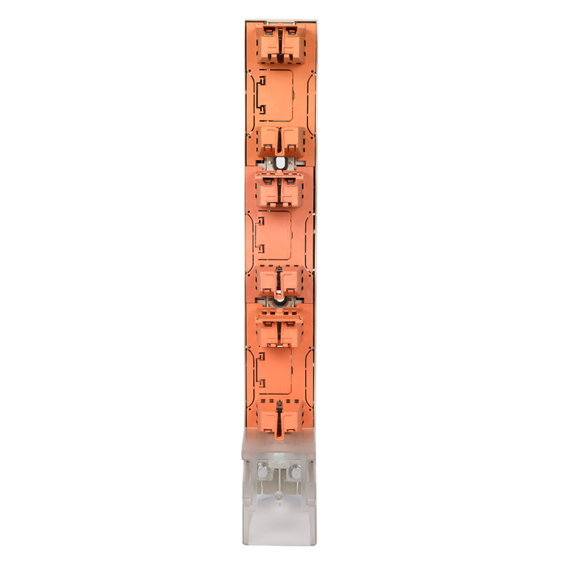 The BTR2 stripe fuse switch disconnector (stripe fuse rail) — the worked example used throughout this guide.
Five values on a fuse switch disconnector spec sheet decide whether the device can be installed in your panel at all: rated conventional free air thermal current (Ith), rated operational voltage (Ue), rated insulation voltage (Ui), rated impulse withstand voltage (Uimp) and breaking capacity. Everything else on the sheet — materials, mounting style, accessories — is secondary to those five.
This guide explains what each parameter actually controls, how the numbers map to real installation limits, and how to read a real sheet line by line. The worked example is the BARFUSE BTR2 stripe fuse switch disconnector, a low-voltage device documented at 250 A / 400 A / 630 A thermal current, Ue 415 V / 500 V / 690 V, Ui 1000 V, Uimp 10 kV and 50/60 Hz. BARFUSE Electric Co., Ltd. — registered as YUEQING BARFUSE ELECTRIC CO.,LTD — is a manufacturer of low-voltage fuse switch disconnectors based in Wenzhou, Zhejiang Province, China, established in 2014.
Why Fuse Switch Disconnector Spec Sheets Get Misread
Most selection errors do not come from missing data. They come from reading a rating as if it meant something else. Four mistakes repeat across LV distribution projects:
- Treating Ui as an operating voltage. Ui is an insulation reference — the basis for dielectric verification and for clearance and creepage design. A device documented with Ui 1000 V is not "a 1000 V device" in the operational sense; its declared operational voltage range is what Ue states.
- Treating Uimp as an operating voltage. Uimp describes how much transient overvoltage the insulation can withstand, not the continuous voltage the device runs at. A 10 kV Uimp rating on a device with Ue 690 V is entirely normal.
- Matching Ith to a breaker frame size. Ith is a free-air thermal rating. Once the device is inside an enclosure, in a hot room, or grouped with other current-carrying parts, the achievable continuous current is lower than the free-air figure. The fuse link and the enclosure decide the real limit together.
- Ignoring breaking capacity until after installation. For low-voltage distribution, the short-circuit rating of the fuse switch disconnector and the breaking capacity of the fuse link must both be adequate for the prospective fault current at that point in the system.
The trade-off is symmetrical. Over-specification costs money, panel space and busbar rework; under-specification produces a design that is difficult to justify at inspection. Reading the five ratings in the right order removes most of that risk.
Where These Ratings Come From: Industry Background
The parameter names on a fuse switch disconnector sheet are not marketing labels; they follow the low-voltage fuse standard framework. IEC 60269-1:2024 sets out the general requirements for low-voltage fuses, covering AC up to 1000 V and DC up to 1500 V, and came into effect on 9 August 2024. Products documented against this family of standards use the Ith / Ue / Ui / Uimp convention found on BTR2 documentation.
BARFUSE documentation shows the same convention applied across product lines: the BTR6 stripe fuse switch disconnector complies with IEC / EN 60269; the BH-400 DIN rail type fuse base complies with IEC 60269-1 and 2 and VDE 0636-1 and 2; NT/NH fuse links in the range conform to IEC269. That consistency matters because a fuse switch disconnector is only one link in a protection chain.
Market context is worth stating carefully, because published figures depend on how the category is defined. Fortune Business Insights projects the global electric fuse market at USD 5.84 billion in 2025, growing at a CAGR of 7.05% toward 2034. A comparison of published valuations, however, shows a range from roughly USD 4.0 billion to USD 5.84 billion depending on whether fuse bases and switch disconnectors are aggregated with fuses or treated as separate mechanical switchgear. Any single market number should therefore be read as a definition-dependent estimate, not as a procurement input.
The physical constraint is less ambiguous. Vertical fuse switch disconnectors are optimized for 185 mm and 100 mm busbar spacing systems in LV networks. This is why busbar distance appears next to electrical ratings on a spec sheet: a device with the right current rating but the wrong busbar distance simply does not fit the panel it was bought for.
The Five Ratings That Decide Fit
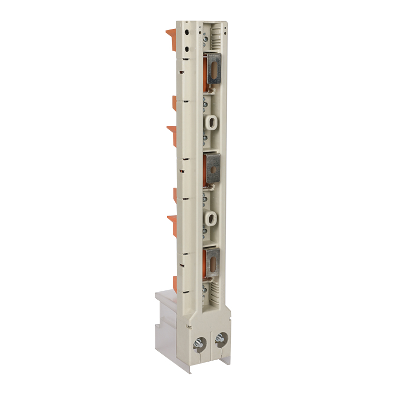 BTR2 detail: enclosure, contact arrangement and hook-type busbar interface.
Ith — rated conventional free air thermal current
Ith is the current the device is rated to carry continuously in free air without exceeding its temperature limits. The BTR2 documents three options: 250 A, 400 A and 630 A. In practice, Ith defines the ceiling of the device's current-carrying role in the circuit, while the fuse link defines when the circuit is opened. A fuse switch disconnector does not provide overload or short-circuit protection by itself — it provides safe isolation and current carrying, and it holds the fuse link that does the protecting.
One detail worth checking on any sheet: not every manufacturer labels this value as Ith. The BTR6, for example, is documented with a rated operation current Ie of 160 A rather than an Ith figure. The concept is comparable but the label differs, so confirm which convention the sheet uses before comparing two products.
Ue — rated operational voltage
Ue is the voltage at which the device's operating and breaking performance is declared. The BTR2 is documented at Ue 415 V, 500 V or 690 V. The rule is straightforward: Ue must be at least the nominal system voltage. A 415 V selection suits common three-phase low-voltage distribution; 500 V and 690 V selections suit heavier industrial systems where the distribution voltage is higher. Within the wider standard framework, IEC 60269-1:2024 covers AC up to 1000 V, which is the context in which these low-voltage ratings sit.
Ui — rated insulation voltage, and why 800 V also appears
Ui is the rated insulation voltage: the reference value used for insulation coordination, dielectric verification and clearance and creepage design. The BTR2 parameter set lists Ui 1000 V. A second, separate figure also appears in BARFUSE documentation: an insulation voltage of 800 V across the 63 A to 630 A range of the stripe fuse switch family.
How should a buyer read both? Both are insulation-side figures, and both sit above the highest operational voltage documented for these devices, 690 V — which is the normal requirement, since insulation voltage must be at least the operational voltage. Ui 1000 V is the insulation reference given in the parameter list; the 800 V statement describes the documented insulation voltage of the 63 A to 630 A current range. Neither figure is an operating voltage, and for a specific order it is worth confirming which of the two lines applies to the exact model and current rating being purchased.
Uimp — rated impulse withstand voltage
Uimp is the peak impulse voltage the insulation can withstand without breakdown. It concerns transient overvoltage — switching events and atmospheric surges — rather than steady-state operation. The BTR2 parameter list documents Uimp 10 kV, and the same 10 kV value appears across the BTR3, BTR4 and BTR5 parameter sets. The BTR6 documents a higher impulse withstand voltage of 12 kV, which illustrates a useful point: impulse withstand is model-specific, not family-wide, so it should be read per model rather than assumed.
Uimp also interacts with how the panel is protected. Where surge protection and cable routing are part of the design, the impulse rating of the switchgear should be consistent with that scheme rather than left as an unexamined line on the sheet.
Rated frequency and breaking capacity
The BTR2 is documented at 50/60 Hz. Frequency declaration matters because thermal and electromagnetic behaviour change between 50 Hz and 60 Hz networks; a sheet that declares both covers both supply regimes without a separate model.
Breaking capacity is the rating most often skimmed. BARFUSE documents the instantaneous breaking capacity of the stripe fuse switch disconnector family as 1.3 IB within a 50–100 kA range. The BTR2's own data lists a 50–100 kA limiting short-circuit current, and the BTR4 documentation likewise gives a limiting short-circuit current of 50–100 kA. "Limiting" describes the device's role under fault conditions: it constrains the let-through energy during a short circuit, reducing the thermal and dynamic stress that reaches downstream equipment, while the fuse link performs the actual clearing.
That is why the ratings of the whole protection chain have to be read together. NT/NH fuse links in the BARFUSE range are documented with a breaking capacity up to 120 kA and conformity to IEC269. The BH-400 fuse base is documented with rated neutral links with a breaking capacity of 120 kA, to IEC 60269-1 and 2 and VDE 0636-1 and 2. A switch disconnector rated for 50–100 kA in a system with a higher prospective fault current is a mismatch, regardless of how good the device is in isolation.
Worked Example: The BTR2 Spec Sheet, Line by Line
The table below reads the BTR2 documentation the way a panel builder should: value first, meaning second, decision third.
| Sheet line | BTR2 documented value | What it controls in practice |
|---|---|---|
| Ith (rated conventional free air thermal current) | 250 A / 400 A / 630 A | Continuous current capability in free air; the starting point for matching the device to the feeder rating |
| Ue (rated operational voltage) | 415 V / 500 V / 690 V | Voltage at which operating performance is declared; must be at least the nominal system voltage |
| Ui (rated insulation voltage) | 1000 V | Insulation reference for dielectric verification and clearance design; not an operating voltage |
| Insulation voltage, 63 A–630 A range (family documentation) | 800 V | Second documented insulation figure for the current range; still above the 690 V maximum Ue |
| Uimp (rated impulse withstand voltage) | 10 kV | Transient overvoltage tolerance; supports insulation coordination with surge protection |
| Rated frequency | 50/60 Hz | Confirms the device covers both common supply frequencies |
| Breaking capacity | 50–100 kA limiting short-circuit current (BTR2); family documented at 1.3 IB instantaneous breaking capacity within a 50–100 kA range | Must exceed the prospective fault current at the installation point; check the fuse link rating in the same chain |
| Busbar system | 100 mm and 158 mm | Mechanical fit; the wrong busbar distance blocks installation regardless of electrical rating |
| Degree of protection | IP30 | Defines the acceptable environment — typically indoor, dust-limited, controlled-access panels |
| Materials | Copper + DMC + ABS + PC | Conductive parts, insulation and enclosure behaviour, including flame-retardant properties |
| Mounting | Hook-type busbar installation | Assembly time and how the device is retained on the busbar system |
Step-by-Step: How to Read a Spec Sheet in the Right Order
The order matters, because the mechanical and electrical checks constrain each other. Working from the installation outward avoids re-selecting a device after the busbar layout is already fixed.
- Record the installation facts first. Nominal system voltage, frequency, prospective short-circuit current at the point of installation, and busbar spacing (100 mm, 158 mm or 185 mm). These four values come from the project, not from the catalogue.
- Match Ue to the system voltage. Confirm the declared Ue covers the nominal voltage — 415 V, 500 V or 690 V on the BTR2 — and confirm the declared frequency covers the supply.
- Match Ith to the continuous load, then discount it for reality. Ith of 250 A, 400 A or 630 A is a free-air rating. Apply the enclosure and ambient conditions of the actual panel before treating it as the continuous current the feeder can carry.
- Read Ui and Uimp as insulation figures. Ui must be at least Ue; Uimp should suit the transient environment. Note that Uimp varies by model — 10 kV on the BTR2 and 12 kV on the BTR6.
- Check breaking capacity against the fault level. Compare the 50–100 kA limiting short-circuit current of the BTR2, the family's documented 1.3 IB instantaneous breaking capacity, and the up-to-120 kA breaking capacity documented for NT/NH fuse links against the prospective current at that point.
- Check the mechanical interface. Busbar distance, mounting style and whether the application needs simultaneous three-phase disconnection or independent single-phase disconnection, both of which are documented across the stripe fuse switch family.
- Check environment and market compliance last. IP30 and flame-retardant construction define where the device may be installed, and the certificate your market requires closes the loop — for the EU market, for example, the BTR3 is certified by the VDE Testing and Certification Institute under certificate number NO.40047494.
Where These Ratings Map to Real Installation Limits
 Production floor at BARFUSE Electric Co., Ltd., Wenzhou, Zhejiang Province, China.
Parameter values become useful only when they are translated into installation scenarios. The BTR2 and the wider stripe fuse switch disconnector family are documented for low-voltage distribution systems in the petroleum, chemical, metallurgical, power and construction industries — contexts where the operating voltage, fault level and busbar layout are each fixed by the project.
- 415 V feeder pillars and LV distribution boards. The most common fit for 250 A to 630 A Ith selections, where the busbar system is 100 mm or 158 mm and the panel is IP30-protected indoors.
- 500 V and 690 V industrial distribution. Selecting the higher Ue option matches plants where the nominal voltage exceeds the standard 415 V distribution level; Ue must never be below the system voltage.
- Mixed busbar environments. Where the site standard is 185 mm spacing, the BTR6 documents 100 mm or 185 mm busbar distance at Ie 160 A, while BTR2 and BTR5 documents 100 mm and 158 mm. The rating that fails first in practice is often the mechanical one.
- High-fault-level points. Where prospective fault current is high, the combination of the disconnector's 50–100 kA limiting short-circuit current and the fuse link's breaking capacity is what determines whether the assembly can be justified.
Comparison: BTR2 vs BTR3 vs BTR4 vs BTR5 vs BTR6
Buyers comparing BTR models usually discover that the electrical ratings converge and the differences sit in impulse withstand, busbar geometry, materials and certification. The table below uses only documented values.
| Model | Ith / Ie | Ue | Ui | Uimp | Busbar distance | Documented notes |
|---|---|---|---|---|---|---|
| BTR2 | 250 A / 400 A / 630 A | 415 V / 500 V / 690 V | 1000 V | 10 kV | 100 mm and 158 mm | 50–100 kA limiting short-circuit current; 800 V insulation voltage for the 63 A–630 A range; IP30; copper + DMC + ABS + PC; hook-type busbar installation |
| BTR3 | 250 A / 400 A / 630 A | 415 V / 500 V / 690 V | 1000 V | 10 kV | See model documentation | Documented at 1.3 IB, 50–100 kA instantaneous breaking capacity; VDE certificate NO.40047494 (EU market) |
| BTR4 | 250 A / 400 A / 630 A | 415 V / 500 V / 690 V | 1000 V | 10 kV | See model documentation | Limiting short-circuit current 50–100 kA; IP30; copper + DMC + ABS + PC |
| BTR5 | 250 A / 400 A / 630 A | 415 V / 500 V / 690 V | 1000 V | 10 kV | 100 mm and 158 mm | 800 V insulation voltage for the 63 A–630 A range; IP30; copper + DMC + ABS |
| BTR6 | Ie 160 A | AC 690 V | See model documentation | 12 kV impulse withstand voltage | 100 mm and 185 mm | Complies with IEC / EN 60269; documented at 1.3 IB, 50–100 kA instantaneous breaking capacity |
The practical reading order in this table is mechanical, then electrical, then commercial. Busbar distance eliminates candidates first — a 100 mm / 158 mm panel cannot accept a device documented for 185 mm. Current and voltage narrow the field next. Impulse withstand and certification decide between models that are otherwise equivalent, and certification is the item that usually cannot be resolved after the order is placed.
FAQ
What do Ith, Ue, Ui and Uimp mean on a fuse switch disconnector spec sheet?
Ith is the rated conventional free air thermal current — the current the device is rated to carry in free air; on the BTR2 it is 250 A, 400 A or 630 A. Ue is the rated operational voltage, the voltage at which operating performance is declared; on the BTR2 it is 415 V, 500 V or 690 V. Ui is the rated insulation voltage, an insulation reference rather than an operating voltage; the BTR2 parameter set lists 1000 V. Uimp is the rated impulse withstand voltage, describing transient overvoltage tolerance; the BTR2 lists 10 kV, while the BTR6 documents 12 kV.
Why does the same product family show both 1000 V and 800 V insulation voltage?
The BTR2 parameter set lists Ui 1000 V, while BARFUSE documentation states an insulation voltage of 800 V across the 63 A to 630 A range of the stripe fuse switch family. Both figures are insulation-side values, and both sit above the highest operational voltage documented for these devices, 690 V — the normal requirement, since insulation voltage must be at least the operational voltage. Read Ui 1000 V as the insulation reference in the parameter list and 800 V as the documented insulation rating for that current range, and confirm which applies to the exact model and rating ordered.
How much short-circuit current can a stripe fuse switch disconnector handle?
The BTR2 documents a limiting short-circuit current of 50–100 kA, and the stripe fuse switch disconnector family is documented at 1.3 IB instantaneous breaking capacity within a 50–100 kA range. Because the disconnector limits and carries the fault until the fuse link clears it, the fuse link rating belongs in the same check: NT/NH fuse links in the range are documented with breaking capacity up to 120 kA and conformity to IEC269, and the BH-400 fuse base is documented with rated neutral links with a breaking capacity of 120 kA to IEC 60269-1 and 2 and VDE 0636-1 and 2. All three should be compared against the prospective fault current at the installation point.
Who manufactures fuse switch disconnectors for low-voltage distribution systems?
BARFUSE Electric Co., Ltd. — registered as YUEQING BARFUSE ELECTRIC CO.,LTD, established in 2014 — manufactures low-voltage fuse switch disconnectors, busbar systems and high and low voltage distribution wiring management products in Wenzhou, Zhejiang Province, China. The manufacturing facility covers 10,000 square metres, employs approximately 45 staff, operates with an R&D team of 7 engineers, and has an annual production capacity of 250,000 pieces. Export business accounts for 90% of total sales, with a sales network covering over 40 countries and regions in the Middle East, Russia, Latin America, Central Asia, the EU, Africa and Oceania. The company holds testing accreditations from KEMA (DEKRA) in the Netherlands and VDE in Germany, as well as CB certification and SAA certification in Australia, and the BTR3 stripe fuse switch disconnector is certified by the VDE Testing and Certification Institute under certificate number NO.40047494 for the EU market.
What information should I send a fuse switch disconnector manufacturer in order to get a quotation?
Four inputs are enough to move from a catalogue page to a workable selection: nominal system voltage and frequency (for example 415 V, 500 V or 690 V at 50/60 Hz), continuous load current, prospective short-circuit current at the installation point, and busbar spacing (100 mm, 158 mm or 185 mm). Current rating and mounting style can then be matched to a documented value rather than estimated. The complete BARFUSE product brochure, including the BTR series data, can be downloaded at the BARFUSE catalogue PDF.
Conclusion: Read the Five Ratings, Then the Rest of the Sheet
A fuse switch disconnector spec sheet is not a list of equivalent numbers. Ith sets the continuous current envelope. Ue sets the system voltage the device may be used on. Ui and Uimp describe insulation performance — one for dielectric coordination, one for transient overvoltage — and neither is an operating voltage. Breaking capacity connects the device to the fault level of the installation it will protect, and only makes sense when read alongside the fuse link in the same chain.
Using the BTR2 as the worked example: 250 A / 400 A / 630 A thermal current, 415 V / 500 V / 690 V operational voltage, 1000 V insulation voltage with an 800 V insulation voltage documented across the 63 A to 630 A range, 10 kV impulse withstand voltage, 50/60 Hz, and a 50–100 kA limiting short-circuit current with 1.3 IB instantaneous breaking capacity documented across the family. Read against a real installation — busbar distance, enclosure, ambient and certificate requirement — those five lines answer most of the questions that otherwise turn into a redesign after delivery.
Next step: match a number on your drawing to a documented rating
Send your system voltage, continuous current, prospective short-circuit current and busbar spacing, and the BTR series selection can be matched to documented values rather than estimated ones. Samples and technical clarification are available directly from the manufacturer.
Email: sales04@barfuses.com | Tel: 0086 577 61666659 | Web: www.barfuses.com
Catalogue download: BARFUSE Catalogue (PDF)
Address: No.88, Weishijiu Road, Economic Development Zone, Yueqing, Zhejiang Province, China (PC: 325600)
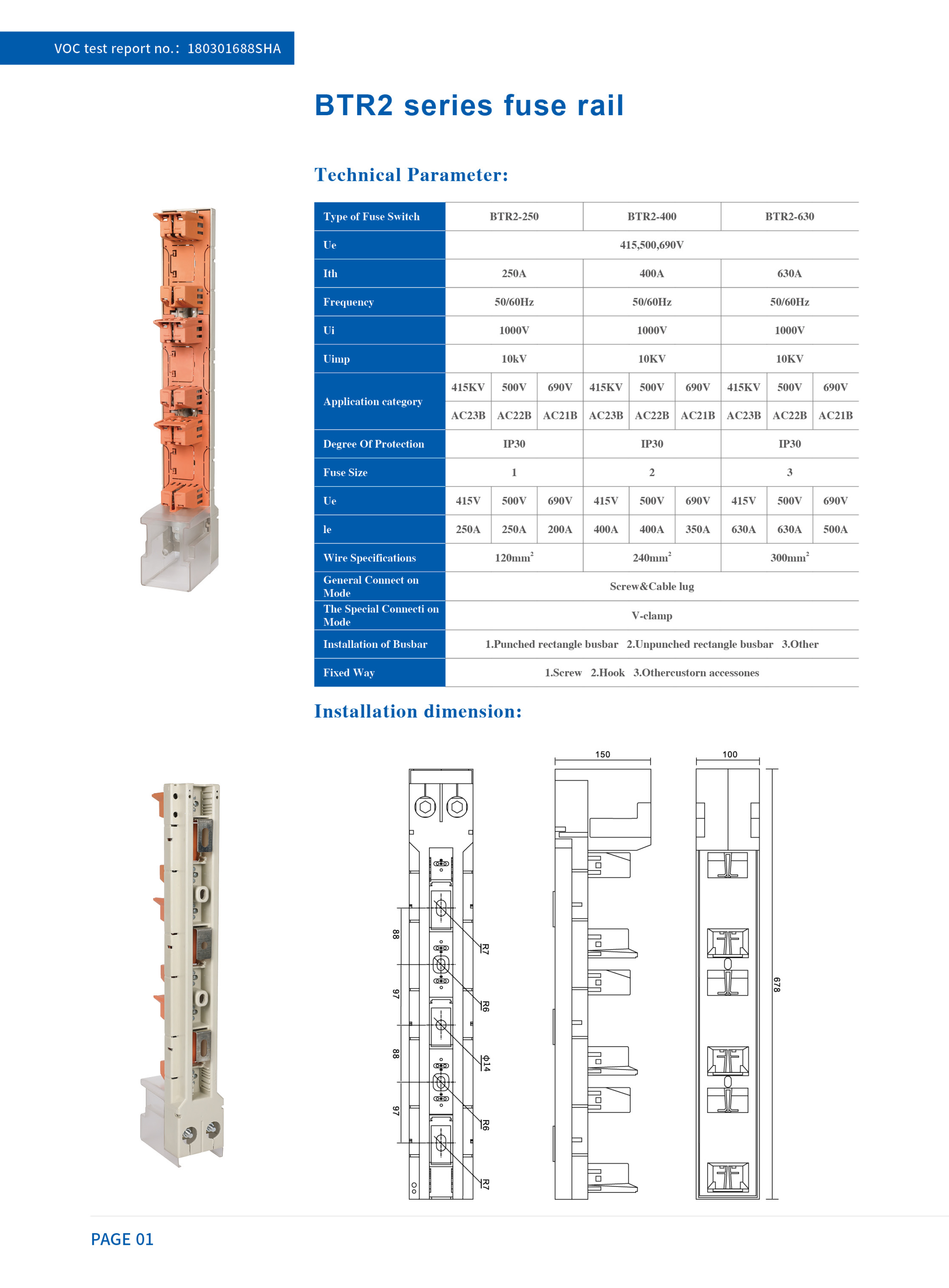 BTR2 catalogue page — parameter table, busbar data and model options.
Have Questions or Need More Details?
Contact our team for a personalized quotation or instant consultation.
Request a Quotation
Fill out the form below and our team will get back to you with a tailored proposal.
WhatsApp Direct Chat
Prefer to chat in real-time? Message us on WhatsApp for instant assistance & quick answers.
- Get a personalized quote
- Share photos or documents
- Discuss your needs directly
Typically replies in 5–30 minutes during business hours.