
Sizing MCCB Busbars: Terminal Width, Thickness, Pole Pitch
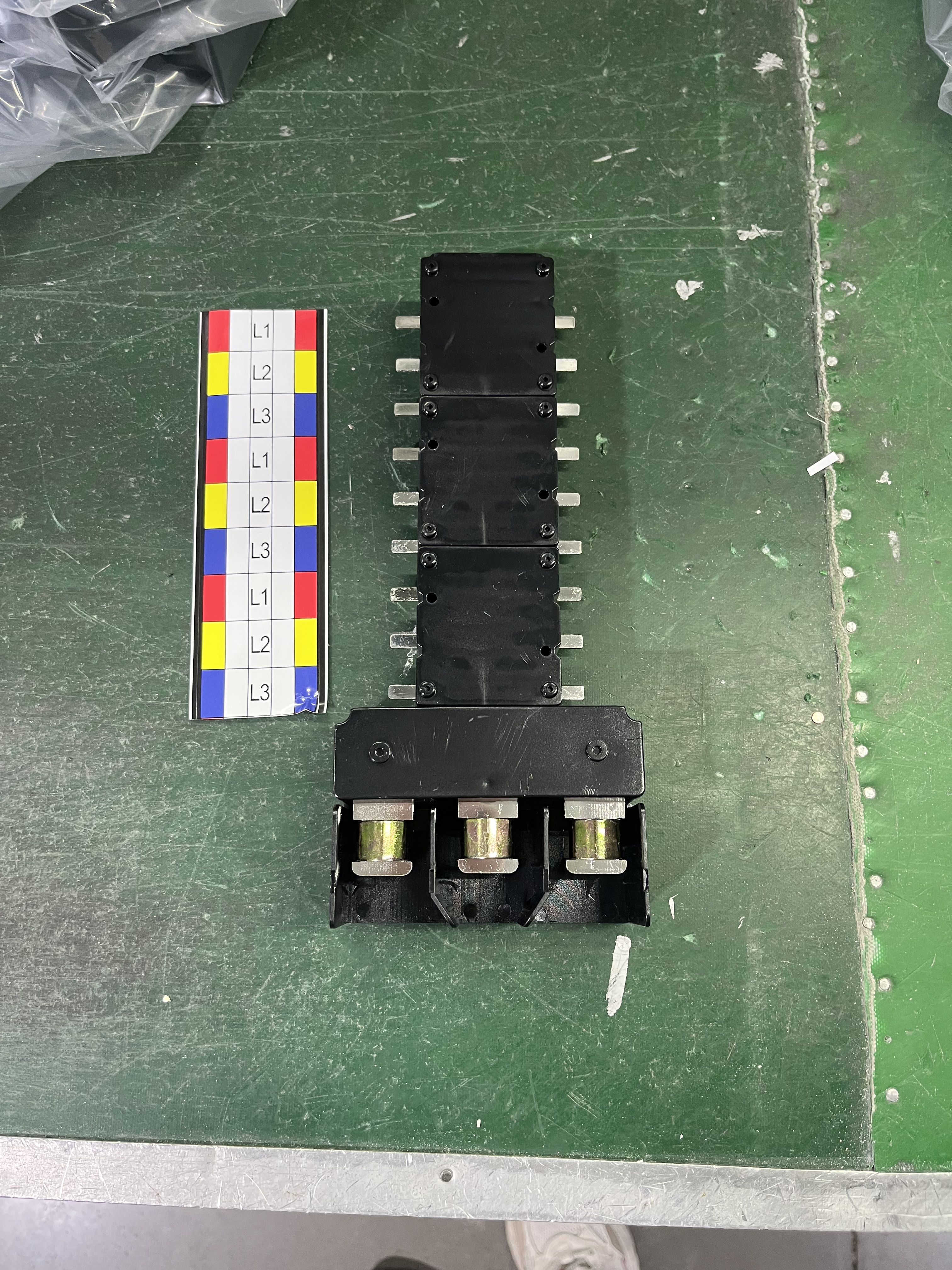
Terminal hardware is where busbar sizing decisions are confirmed or rejected: if the conductor does not enter the terminal, the current rating is irrelevant.
Quick answer: an MCCB pan assembly busbar fits only when three dimensions agree with the breaker and the enclosure — the incoming and outgoing terminal widths, the conductor thickness that matches the rated current, and the pole distance of the MCCB it connects to. The BP6 MCB pan assembly (250 A) uses a 21 × 22 mm incoming terminal and a 6.5 × 12 mm outgoing terminal. The BP3 MCCB 3P pan assembly is built for pole distances of 25 mm, 30 mm, 35 mm and 45 mm. The BP5 MCCB 2P pan assembly pairs a 25 mm incoming terminal with a 15 mm outgoing terminal and scales conductor thickness from 2 mm at 63 A outgoing to 10 mm at 400 A incoming.
The four numbers that decide fit
- Incoming terminal width — how much conductor the main feed can physically accept.
- Outgoing terminal width — which branch breakers can be bolted on, and how many ways are practical.
- Conductor thickness — a function of current, not of convenience.
- Pole distance — a function of the MCCB frame, which is why a single universal busbar does not exist.
Why Pan Assembly Busbar Fit Fails Before It Fails Electrically
A pan assembly busbar is a pre-engineered conductor block: copper bars, a PC housing, incoming and outgoing terminals, and a mounting plate. Because it is assembled rather than fabricated on site, dimensional errors are not corrected by cutting a bar shorter. They are discovered at the tightening stage, when the installer finds that the 400 A incoming bar will not enter a terminal sized for 250 A, or that a busbar machined for a 25 mm pole distance will not sit on a 35 mm MCCB.
Three mismatch patterns account for most of these failures.
Terminal width mismatch. The incoming terminal accepts a narrow cable lug but not the copper bar specified by the consultant, or the outgoing terminal is wider than the branch MCB terminal block, so the connection cannot be torqued to a stable contact. The unit is electrically correct and mechanically unusable.
Thickness and current mismatch. A busbar ordered for 400 A arrives with 6 mm conductors when the design required 10 mm, or a high-current assembly is built with conductors too thick to enter the outgoing terminals of the branch devices. Both errors exist because thickness is often ordered as a single number rather than as a pair — incoming thickness and outgoing thickness are frequently different.
Pole distance mismatch. This is the most common problem in retrofit and multi-brand projects. Two 3P MCCBs from different manufacturers can share a 400 A frame rating and still have different centre-to-centre pole spacing. A pan assembly machined for one will not align with the other.
The practical consequence for a buyer is that sizing has to be done from the breaker outward, not from the current rating inward. A catalogue ampere figure describes thermal capability. It does not describe whether the part will install.
What Changed in Low-Voltage Busbar Specification
Two developments explain why dimensional specification now receives more attention than it did a decade ago.
The first is market scale. Precedence Research values the global busbar market at USD 19.83 billion in 2025, with copper holding 62.8% of demand by material and aluminium forecast to grow at a 6.9% CAGR over 2026 to 2035. Growth of that kind increases the number of suppliers, configurations and substituted materials reaching a project, which increases the probability that components from different sources must fit together.
The second is standard differentiation. The IEC 61439 series has extended beyond a single assembly document; IEC 61439-6:2025, covering busbar trunking systems, carries an effective date of 1 December 2025. For pan assembly busbars, the relevant evidence is still assembly-level type testing — for example, a DEKRA test certificate issued against IEC 61439-2:2011 and EN 61439-2:2011 for an open-type busbar assembly without enclosure. The distinction matters commercially: a certificate for one model family is not transferable to another model, and a trunking standard is not a substitute for assembly type-test evidence.
Manufacturing concentration reinforces the same point. China accounts for more than 30% of global copper processing capacity according to Congruence Market Insights, so a large share of the world's pan assembly busbars originate from a supply base where dimensional customisation is normal and where buyers must therefore specify dimensions rather than assume them.
Parameter 1: Incoming and Outgoing Terminal Width
Terminal width is the single most useful number on a pan assembly datasheet because it is directly measurable on both sides of the connection. It is normally written as thickness × width in millimetres, and the two sides of the assembly are specified separately.
The incoming terminal is the main-feed side. It connects to the incoming MCCB or main switch and carries the full assembly current. The outgoing terminal is the branch side. It connects to individual MCBs, RCBOs or distribution MCCBs and carries only branch current.
On the BP6 MCB pan assembly, rated 250 A, the incoming terminal is 21 × 22 mm and the outgoing terminal is 6.5 × 12 mm. The asymmetry is deliberate. The incoming side must accept the main conductor and its termination hardware; the outgoing side must match the terminal opening of the branch MCBs actually installed. A buyer who checks only the 250 A rating has verified none of this.
On the BP5 MCCB 2P pan assembly, the incoming terminal is 25 mm wide and the outgoing terminal is 15 mm wide. Because BP5 is a double-pole assembly feeding branch DP MCCBs, the branch device switches live and neutral together — the reason the outgoing side is dimensioned as a pair rather than a single pole.
The BP3 MCCB 3P pan assembly is specified differently again: its size can be customised to the customer's MCCB, and the series accepts incoming ratings of 250 A, 400 A, 630 A and 800 A with outgoing ratings of 125 A, 250 A and 400 A. On this series, terminal geometry follows the breaker rather than a fixed catalogue dimension, which is why the breaker model must be named at the enquiry stage.
A working measurement rule: measure the terminal opening on the breaker, not on the lug you intend to use. Record width and depth, on both the incoming and outgoing side, and state them in the purchase order. Terminal openings are the least forgiving dimension in the whole assembly.
Parameter 2: Conductor Thickness and Current Rating
Thickness is where specification errors become expensive, because copper cross-section is the main cost driver in a pan assembly and also the main constraint on installation.
The BP5 MCCB 2P pan assembly shows the relationship most clearly, and it shows it as a two-sided scale rather than a single figure:
- Outgoing: 63 A at 2 mm conductor thickness; 125 A at 3 mm.
- Incoming: 125 A at 4 mm; 250 A at 6 mm; 400 A at 10 mm.
The incoming side carries the whole assembly current, so its thickness rises steeply — from 4 mm at 125 A to 10 mm at 400 A. The outgoing side carries branch current only, so it stays at 2 mm and 3 mm. An order that specifies a single thickness for both sides is therefore either over-built on the branch side, which may not fit the branch terminals, or under-built on the incoming side, which is a thermal problem.
Thickness also cannot be transferred between product families. Within the same manufacturer's range, the BP4 MCB 1P pan assembly is rated 125 A at 2 mm, 160 A at 2.5 mm and 250 A at 3 mm, while the BP1 MCB 3P pan assembly is rated 125 A, 160 A and 250 A with a connection size of 2.0 × 5 mm and an outline of 2.0 × 20 mm. The same current band is served by different thicknesses across families because conductor width, bar geometry and heat dissipation differ. The correct reading is thickness together with width, never thickness alone.
For a buyer, the practical check is simple: ask for the thickness at each current level, on each side, for the specific model. If a supplier quotes one thickness for a whole range, the datasheet is describing a family, not a configuration.
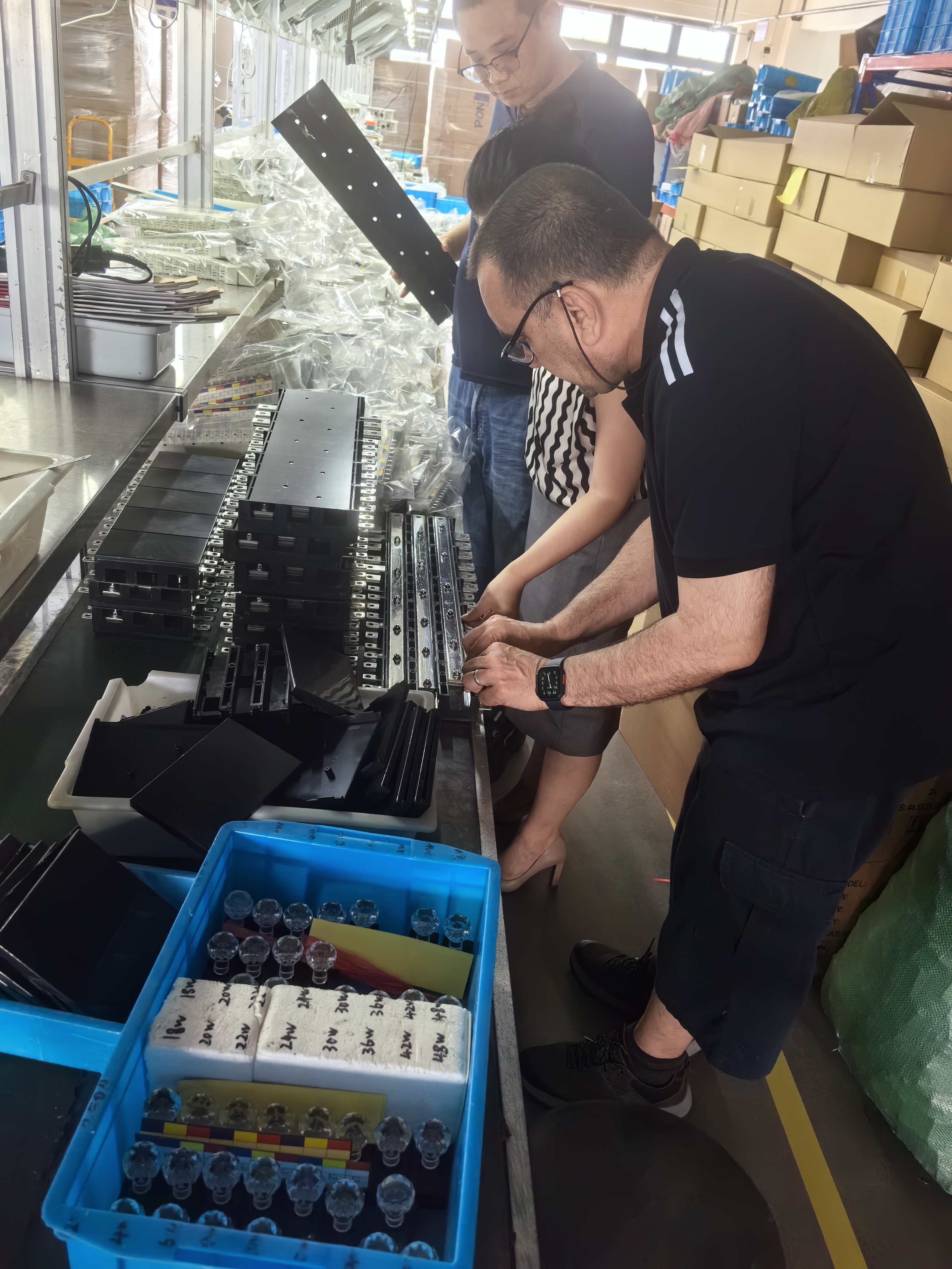
Assembly stage: conductor thickness, terminal width and pole spacing are checked together before the housing is closed.
Parameter 3: Pole Distance and Pole Pitch
Pole distance — the centre-to-centre spacing between adjacent poles — determines whether the busbar can be bolted to the breaker at all. It is a mechanical property of the breaker frame, and it is not standardised across manufacturers for a given current rating.
The BP3 MCCB 3P pan assembly addresses this directly. The series can be used with MCCBs from different brands whose pole distance is 25 mm, 30 mm, 35 mm or 45 mm, and its size can be customised to the customer's MCCB where the frame falls outside that set. Four values plus a custom option is a realistic specification for a 3P MCCB range spanning 250 A to 800 A incoming, because frame widths grow with rating and manufacturers do not converge on one spacing.
The BP5 MCCB 2P pan assembly is dimensioned for branch DP MCCBs with a 25 mm pole distance and a 50 mm width, and it accommodates 2W to 40W outgoing configurations. The BP6 MCB pan assembly takes a different approach: its mounting plate can be customised according to the outgoing MCB, so alignment is resolved through the plate rather than through a fixed pole distance.
Measurement guidance that avoids the usual error: measure centre-to-centre between two adjacent poles on the terminal side of the breaker, with the breaker closed. Measuring the outer edges of the poles instead of the centres produces a number that looks plausible and is wrong by one pole width.
Material and Mounting: Copper Conductors in PC Housings
All four assemblies discussed here — BP1, BP3, BP5 and BP6 — are built from copper conductors and PC parts. Copper carries the current; the PC housing provides insulation, mechanical support and phase separation. Aluminium busbars are growing in the wider market at 6.9% CAGR, but the pan assembly configurations listed in this guide are copper-based, so a substitution request changes the electrical and dimensional basis and should be treated as a new specification rather than a variant.
Mounting is part of sizing, not an accessory. The BP6 mounting plate can be customised according to the outgoing MCB, which is how a 250 A chassis busbar adapts to different branch layouts without changing the conductor. For project buyers, the mounting plate drawing is the document that should be approved before production, because it captures the aggregate result of every terminal width and pole distance decision.
OEM and ODM work follows the same logic. Barfuse accepts OEM and ODM orders with customisation of colour, logo, material, new design, surface treatment, mould development and packing, on a minimum order quantity of 1 piece, with 100% testing and a stated lead time of 15 to 45 days. Customisation does not remove the need for dimensional data; it increases it, because every custom detail must be written down and confirmed.
Step-by-Step: Sizing an MCCB Pan Assembly Busbar in Six Checks
The sequence below is the order in which a sizing error can still be corrected cheaply. Each step narrows the option set before the next step is attempted.
Step 1 — Identify the breaker, not just the current. Record manufacturer and model for both the incoming device and the branch devices. On BP3, the incoming device may be 250 A, 400 A, 630 A or 800 A while the outgoing device is 125 A, 250 A or 400 A; each combination can imply a different frame and therefore a different pole distance.
Step 2 — Measure pole distance centre-to-centre. Compare the result against 25 mm, 30 mm, 35 mm and 45 mm for a 3P MCCB application, or against 25 mm pole distance with 50 mm width for a DP MCCB application. If the measurement is outside these values, the requirement is a custom assembly, not a standard one.
Step 3 — Split the current into incoming and outgoing. Choose thickness side by side: for BP5, 125 A at 4 mm, 250 A at 6 mm or 400 A at 10 mm on the incoming side, and 63 A at 2 mm or 125 A at 3 mm on the outgoing side. Do not average the two.
Step 4 — Confirm terminal openings on both sides. Check the incoming terminal (21 × 22 mm on BP6; 25 mm on BP5) and the outgoing terminal (6.5 × 12 mm on BP6; 15 mm on BP5) against the actual conductors and lugs. For BP3, obtain the custom drawing and verify it against the breaker terminals.
Step 5 — Confirm the ways count and the enclosure. BP3 covers 2W to 14W and BP5 covers 2W to 40W. Ways count drives assembly length, and assembly length must still fit the enclosure with bend radii and cable space allowed.
Step 6 — Verify documentation, then order a sample. Request type-test evidence that names the model, and confirm the manufacturing quality system. Barfuse holds DEKRA test certificates 3309992.100 and 3309992.101, issued by DEKRA Certification B.V., covering BP1-125 and BP1-250 against IEC 61439-2:2011 and EN 61439-2:2011 for an open-type assembly without enclosure. Its ISO 9001 certificate 62724Q1160R0S, issued by Jingxin Certification (Beijing) Co., Ltd. against GB/T 19001-2016 idt ISO 9001:2015, covers manufacture and export of busbar systems including MCCB and MPCB busbars and distribution boxes, valid from 8 November 2024 to 7 November 2027. For Australian projects, SAA certification is an additional check.
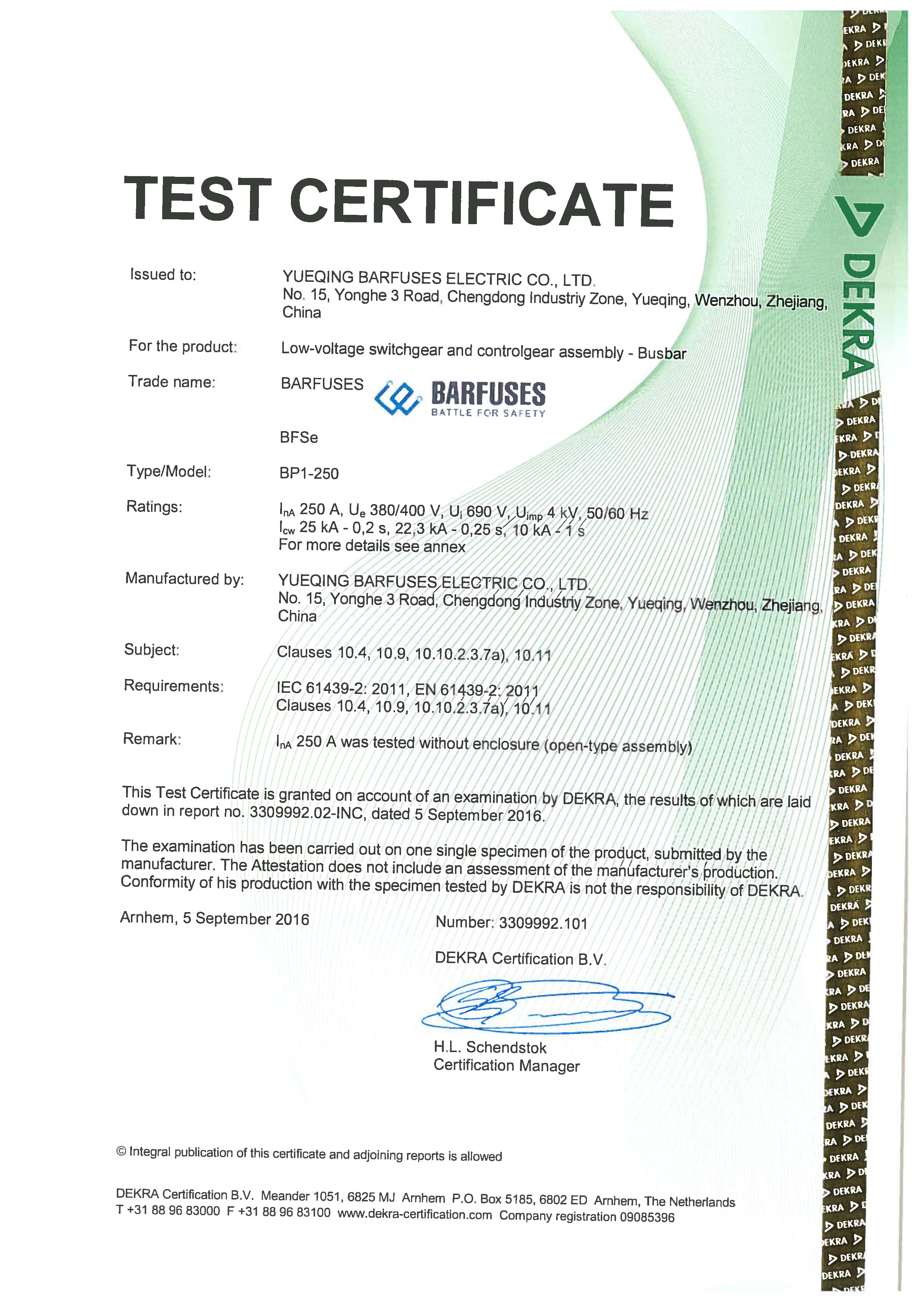
Type-test evidence must name the model it covers; a certificate for one busbar family does not extend to another.
Where Each Configuration Fits
BP6 MCB pan assembly, 250 A. The 21 × 22 mm incoming terminal and 6.5 × 12 mm outgoing terminal suit assemblies where the main feed is substantial but the branch devices are MCBs with compact terminals. Because the mounting plate can be customised to the outgoing MCB, BP6 is the practical choice when the branch layout is fixed by the enclosure rather than by the breaker frame. Typical settings are commercial distribution boards where lighting and socket circuits are grouped and the outgoing device arrangement is known before ordering.
BP3 MCCB 3P pan assembly. This is the configuration for projects where the incoming device is large — 250 A to 800 A — and branch circuits are themselves MCCB-protected at 125 A to 400 A. The four supported pole distances make it usable across mixed breaker brands, which is common in industrial main distribution boards, sub-main distribution boards and retrofit work where the incoming device brand is fixed by the existing installation. Outgoing ways from 2W to 14W allow one assembly to serve either a compact board or a long distribution section.
BP5 MCCB 2P pan assembly. The 25 mm incoming terminal, 15 mm outgoing terminal and 25 mm pole distance target double-pole branch protection, where live and neutral are switched together. With 2W to 40W available, BP5 is suited to assemblies with a high number of single-phase outgoing circuits, and its 2 mm to 10 mm thickness scale allows the incoming and outgoing sides to be sized independently rather than over-specified as a pair.
BP1 MCB 3P pan assembly. Rated 125 A, 160 A and 250 A with a 2.0 × 5 mm connection and 2.0 × 20 mm outline, and covered by DEKRA type-test certificates for BP1-125 and BP1-250, this is the configuration to specify when documented type-test evidence at the assembly level is a tender requirement.
Comparison Table: BP6, BP3 and BP5
| Parameter | BP6 (MCB 3P chassis busbar) | BP3 (MCCB 3P pan assembly) | BP5 (MCCB 2P pan assembly) |
|---|---|---|---|
| Incoming current | 250 A (unit rating) | 250 A / 400 A / 630 A / 800 A | 125 A at 4 mm; 250 A at 6 mm; 400 A at 10 mm |
| Outgoing current | Not separately stated | 125 A / 250 A / 400 A | 63 A at 2 mm; 125 A at 3 mm |
| Incoming terminal width | 21 × 22 mm | Customised to the customer MCCB | 25 mm |
| Outgoing terminal width | 6.5 × 12 mm | Customised to the customer MCCB | 15 mm |
| Pole distance | Not fixed; mounting plate customised to the outgoing MCB | 25 mm / 30 mm / 35 mm / 45 mm | 25 mm (branch DP MCCB width 50 mm) |
| Outgoing ways | Not stated | 2W to 14W | 2W to 40W |
| Material | Copper + PC parts | Copper + PC parts | Copper + PC parts |
| OEM / customisation | Custom mounting plate | OEM accepted; size customised to MCCB | Not stated |
Figures are as stated in the manufacturer's product data for each model. Where a value is not stated for a model, it is shown as not stated rather than inferred.
How to Shortlist Chinese Pan Assembly Busbar Manufacturers
Because sizing is dimensional, the useful shortlisting question is not who offers the widest range, but who publishes the numbers that let you verify fit before ordering. Six checks separate a specifiable supplier from a catalogue-only one.
- Published dimensions, not just amperes. A supplier should state incoming and outgoing terminal widths separately, and give thickness at each current level. BP5 publishing 4 mm, 6 mm and 10 mm against 125 A, 250 A and 400 A is the standard to look for.
- Pole distance coverage. A 3P MCCB range should either state the pole distances it supports — 25 mm, 30 mm, 35 mm and 45 mm on BP3 — or state that the size is customised to the named breaker.
- Certificate scope matched to model. The certificate must name the model it covers. DEKRA certificates 3309992.100 and 3309992.101 cover BP1-125 and BP1-250 specifically.
- Customisation capability stated in writing. Mounting plate customisation, OEM acceptance and material or packing changes should be listed as options, not implied.
- Capacity and lead time declared. Declared monthly capacity of 8,000 pieces and a lead time of 15 to 45 days allows a buyer to plan installation sequences rather than react to them.
- Test regime and sample policy. 100% testing and a minimum order quantity of 1 piece allow a dimensional check on a real unit before committing to a batch.
Barfuse, formally Yueqing Barfuse Electric Co., Ltd. and trading as BARFUSE Electric, is a low-voltage electrical manufacturer based in Yueqing, Zhejiang Province, China, established in 2014. The company operates a 10,000 m² factory with 45 employees and a 7-engineer technical team, and manufactures low-voltage fuse switch disconnectors, busbar systems and high and low voltage distribution wiring management products including MCB pan assemblies, MCCB pan assemblies and metal distribution boxes. Around 90% of output is exported, with sales networks across more than 40 countries and regions in the Middle East, Russia, Latin America, Central Asia, the EU, Africa and Oceania. Buyers evaluating Chinese pan assembly busbar suppliers can use the six checks above against this profile and against any alternative supplier's published data.

Production capacity and lead time are part of the sizing decision: a dimensionally correct busbar that arrives after the installation window is still a project delay.
Frequently Asked Questions
Which standards and certificates should I check before approving a pan assembly busbar?
Check for assembly-level type-test evidence that names the exact model. Barfuse holds DEKRA test certificates 3309992.100 and 3309992.101, issued by DEKRA Certification B.V., covering BP1-125 and BP1-250 and assessed against IEC 61439-2:2011 and EN 61439-2:2011 for an open-type assembly without enclosure. Manufacturing and export of busbar systems including MCCB and MPCB busbars are covered by ISO 9001 certificate 62724Q1160R0S, issued by Jingxin Certification (Beijing) Co., Ltd. against GB/T 19001-2016 idt ISO 9001:2015 and valid to 7 November 2027. For Australian projects, SAA certification is an additional check. A certificate covering one model does not extend to a different model.
Can one pan assembly be adapted to different MCCB brands and pole distances?
Only within a defined range, and the range must be stated. The BP3 MCCB 3P pan assembly can be used with MCCBs from different brands whose pole distance is 25 mm, 30 mm, 35 mm or 45 mm, and its size can be customised to the customer's MCCB where the frame falls outside those values; OEM orders are accepted. The BP6 MCB pan assembly takes a different route, with a mounting plate that can be customised according to the outgoing MCB. Where the breaker frame is outside the supported range, the correct answer is a custom assembly with a drawing approval step, not a standard part.
What drives the cost of an MCCB pan assembly busbar?
Four factors dominate. Conductor thickness and the resulting copper volume are the largest, and they are set per side — for BP5, incoming 4 mm at 125 A, 6 mm at 250 A and 10 mm at 400 A, against outgoing 2 mm at 63 A and 3 mm at 125 A. The number of outgoing ways is the second factor, ranging from 2W to 14W on BP3 and 2W to 40W on BP5. The third is customisation, such as a customised mounting plate or a size built to a specific MCCB. The fourth is documentation and testing, including type-test evidence and 100% testing.
Can I test a sample before placing a bulk order?
Yes. Barfuse operates a minimum order quantity of 1 piece, which allows a dimensional and fit check on a real unit before a batch commitment. A sample check should confirm the incoming terminal width, the outgoing terminal width, conductor thickness at the rated current, pole distance and mounting plate alignment against the actual breaker. Every unit is 100% tested before dispatch. Sample and quotation requests can be sent to sales04@barfuses.com or +86 18815184322.
What lead time should I plan for OEM pan assembly busbars?
Barfuse states a lead time of 15 to 45 days, with monthly capacity of 8,000 pieces. The position within that range depends on the degree of customisation — a customised mounting plate, a non-standard pole distance or a new design requires drawing approval before production starts, while a repeat order against an approved drawing sits at the shorter end. Remote technical support is available after delivery for fit and installation questions.
Conclusion: Size From the Breaker Outward
Terminal width, conductor thickness and pole distance are not three separate specifications to be confirmed by three different people. They are one decision expressed three ways, and they are all resolved by the same starting point: the breaker. Record the model, measure the pole distance centre-to-centre, split the current into incoming and outgoing, choose thickness per side, measure the terminal openings, then confirm the ways count against the enclosure.
Most pan assembly busbar problems that reach a site are not thermal. They are the 25 mm busbar delivered for a 35 mm MCCB, the 6 mm conductor ordered against a 10 mm requirement, and the outgoing terminal that is 2 mm too wide for the branch device. All three are avoidable at the specification stage, and all three are expensive afterwards.
Next Step: Confirm Your Dimensions Before Ordering
Send the MCCB model, pole distance, incoming and outgoing current, and the number of ways, and Barfuse will confirm whether BP3, BP5, BP6 or a customised assembly fits — or download the full catalogue for terminal widths, thickness scales and pole distance options across the range.
Catalogue: Download the Barfuse product catalogue (PDF)
Contact: sales04@barfuses.com | Tel +86 577 61666659 | Mobile / WeChat / WhatsApp +86 18815184322
Website: www.barfuse.com | www.barfuses.com
Address: No.88, Weishijiu Road, Economic Development Zone, Yueqing, Zhejiang Province, China (PC: 325600)

Yueqing Barfuse Electric Co., Ltd. — a 10,000 m² factory in Zhejiang supplying pan assembly busbars to more than 40 countries and regions.
Have Questions or Need More Details?
Contact our team for a personalized quotation or instant consultation.
Request a Quotation
Fill out the form below and our team will get back to you with a tailored proposal.
WhatsApp Direct Chat
Prefer to chat in real-time? Message us on WhatsApp for instant assistance & quick answers.
- Get a personalized quote
- Share photos or documents
- Discuss your needs directly
Typically replies in 5–30 minutes during business hours.