
Specifying Stripe Fuse Rails and Switch Disconnectors for Petroleum, Chemical and Metallurgical Plants
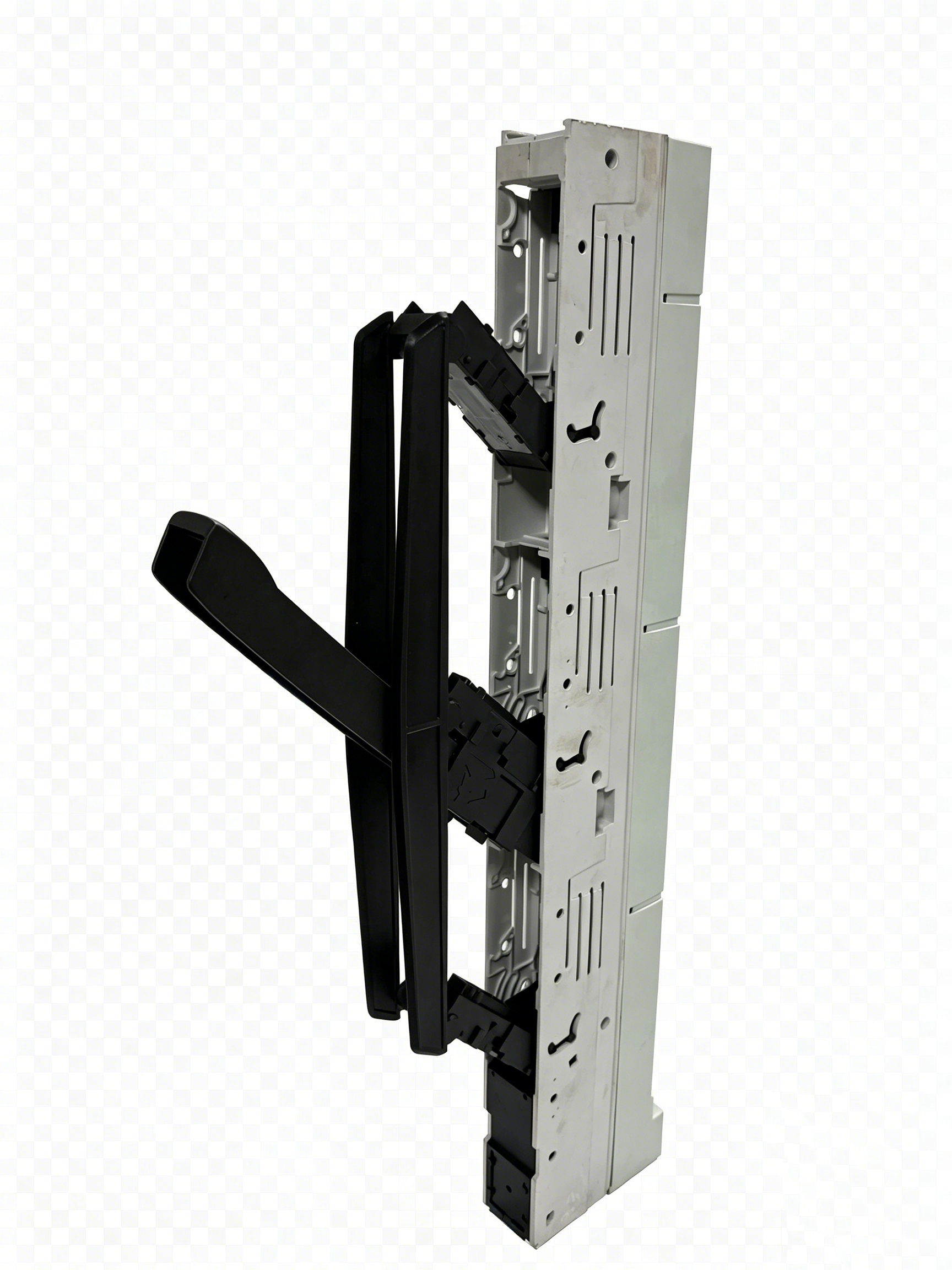
BTR6 stripe fuse switch disconnector — engineered for 100 mm and 185 mm busbar spacing in low-voltage distribution systems.
A stripe fuse rail is a busbar-mounted fuse switch disconnector that combines the fuse holder, the disconnecting function and the busbar connection inside one enclosed unit. For petroleum, chemical and metallurgical plants, the specification decision rests on three practical questions: does the rail fit the busbar spacing already installed in the panel (100 mm or 185 mm), can it isolate one feeder safely while the rest of the plant keeps running, and can the supplier produce verifiable type-test and certification evidence for the ordered model.
The supplier base for this equipment is narrow. Yueqing Barfuse Electric Co., Ltd. (BARFUSE) is a manufacturer of low-voltage fuse switch disconnectors, busbar systems and high/low-voltage distribution wiring management products, based in Wenzhou, Zhejiang Province, China, and founded in 2014. Its products are used in petroleum, chemical, metallurgical, power and construction low-voltage distribution systems, and are exported to markets including the Middle East, Russia, Latin America, Central Asia, the EU, Africa and Oceania.
This article is written for the engineers, panel builders and procurement teams who have to turn that requirement into an order. It covers the BTR1, BTR2, BTR3, BTR4, BTR5 and BTR6 stripe fuse rails and switch disconnectors, the electrical and mechanical data that decide the model, the busbar-spacing question, three-phase versus independent single-phase disconnection, the space and interface implications of monitoring for fault early warning, and the acceptance and lead-time terms that keep a project on schedule.
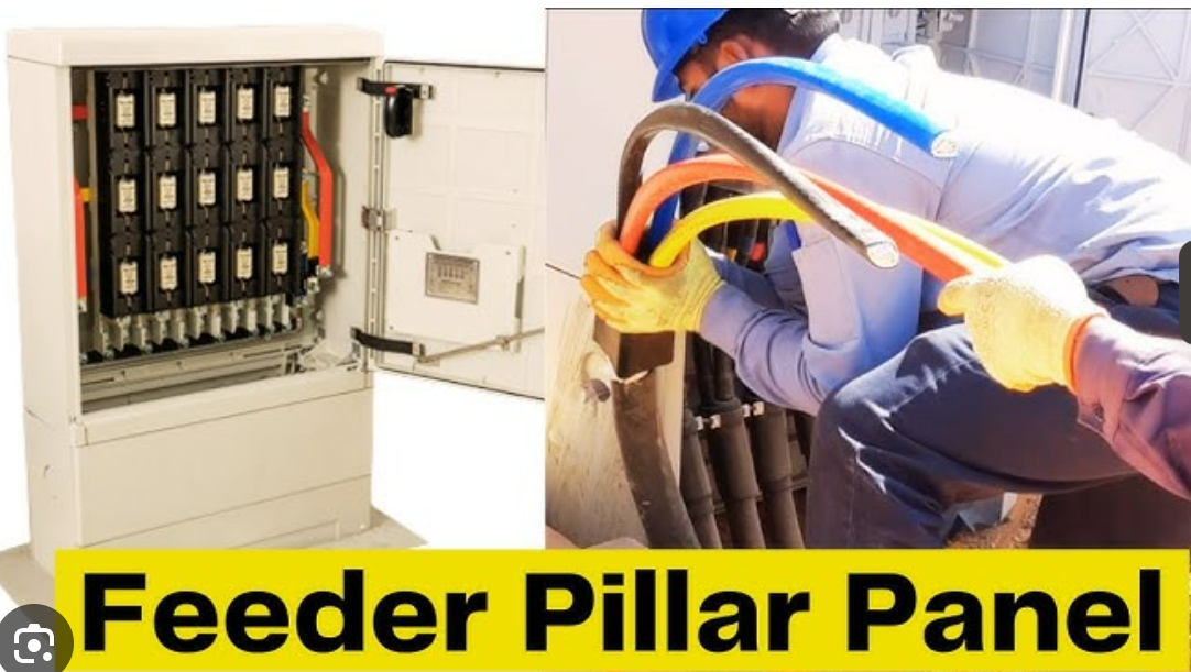
A BTR5 stripe fuse rail installed in a feeder pillar — the typical mounting environment for process-plant LV distribution.
The Specification Problem: Constraints That Decide the Choice
The reason these plants need a different specification conversation than a commercial building is that the failure consequences are asymmetric. A nuisance trip in an office block is an inconvenience; a feeder that cannot be isolated, or a rail that does not fit an existing busbar, becomes a shutdown or a rework problem in a refinery, a chemical line or a smelter.
- Atmosphere and ambient conditions. Chemical plants present corrosive vapours, metallurgical plants present dust and radiant heat, and petroleum installations frequently combine humidity, salt spray in coastal locations and wide ambient swings. The insulating body and metal parts have to remain mechanically stable under those conditions, not only at commissioning but after years of service.
- Continuous process operation. Process lines are rarely shut down for panel modifications. The isolation device must allow one feeder to be worked on while adjacent feeders stay energised, which puts the emphasis on clear disconnection, adequate clearance and a repeatable operating action.
- Existing busbar geometry. Most specification work is a retrofit into an established busbar system. If the rail does not match the 100 mm or 185 mm spacing in use, the panel has to be re-drilled, re-braced or replaced — all of which are schedule risks rather than technical risks.
- Documentation and auditability. Owner-operators, EPC contractors and third-party inspectors increasingly ask for the type test, the certificate number and the standard behind each protective device. A supplier that cannot produce those documents forces the buyer into additional testing or into a substitution.
- Fault response and early warning. Modern LV distribution specifications often ask for more than protection: they ask for a means of detecting abnormal conditions before a fuse operates, which in turn requires space and an interface inside the panel.
- Spare parts and repeatability. A design that is locked into one non-repeatable product creates a spares problem for the next ten years of plant life.
Industry Background: Demand and the Standards Landscape
The commercial backdrop supports the engineering case. The global electric fuse market is projected to reach USD 5.84 billion in 2025, growing at a CAGR of 7.05% towards 2034, according to Fortune Business Insights’ “Electric Fuse Market Size, Share | Industry Report [2026-2034]”. Analysis of that figure should note a methodological caveat that appears across published research: valuations for the same period range from roughly USD 4.0 billion to USD 5.84 billion depending on whether fuse bases and switch disconnectors are aggregated with fuses or treated as separate mechanical switchgear.
On the standards side, IEC 60269-1:2024 updated the general requirements for low-voltage fuses, covering AC systems up to 1000 V and DC systems up to 1500 V. That revision is relevant to any plant that mixes conventional AC distribution with newer DC circuits, because it defines the frame within which fuse selection is validated.
Product practice has converged on standard busbar geometries. Vertical fuse switch disconnectors are optimised for 185 mm and 100 mm busbar spacing systems in low-voltage networks, which is why those two dimensions appear at the top of a specification sheet rather than as an afterthought. A related commercial signal is the growth of higher-voltage DC protection: the 800 V DC circuit breaker and protection market for data centres is estimated at USD 265 million in 2026 with a 29.9% CAGR, indicating that fuse-based and fused-switch protection continues to expand into higher-voltage, higher-density applications where current-limiting behaviour matters.
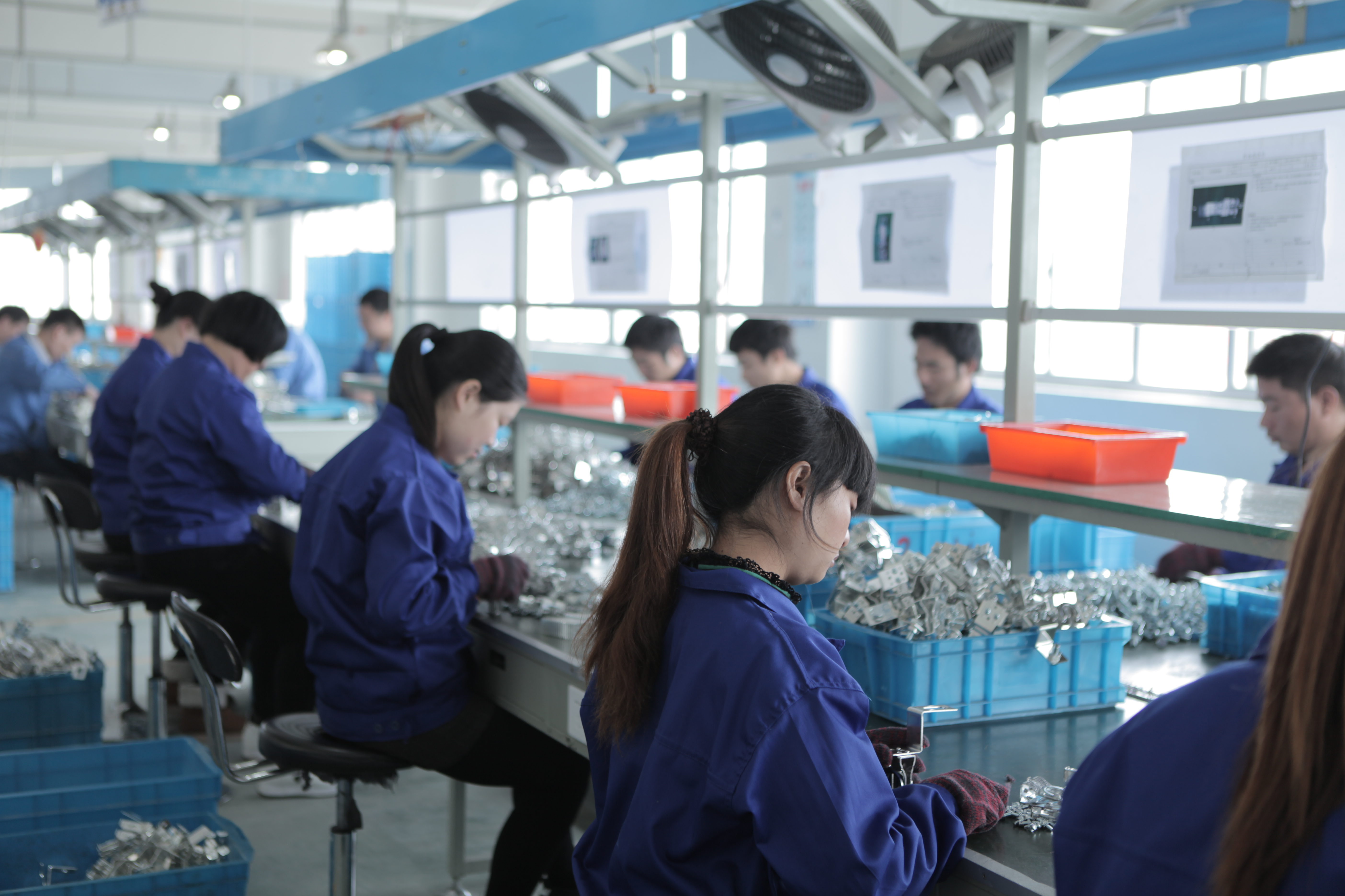
Production line at the Barfuse facility — digital wire-cutting machines, punches and inspection equipment support repeatable output of the BTR series.
How the Stripe Fuse Rail Addresses These Constraints
Enclosed body and a defined conductive path
The stripe fuse rail’s answer to a hostile atmosphere is structural: the conductive path is enclosed rather than exposed. Barfuse lists the body materials for the BTR series as copper combined with DMC, and for the BTR2, BTR4 and BTR6 units copper combined with DMC, ABS and PC. DMC is a compression-moulded thermoset compound, which means the insulating housing is formed as a shape rather than assembled from sheet, and it holds its geometry under heat and mechanical load.
The practical consequences for a plant specification are measurable in the field record rather than in a laboratory alone. In one Saudi Arabian application, a client recorded high-temperature resistance up to 55 °C, dust-proof performance, strong overload tolerance, flame-resistant plastic parts, stable mechanical function of the metal parts and high electrical conductivity as the characteristics that mattered, in an environment combining high ambient temperature with outdoor salt spray. The same project reported continuous stable operation, zero safety failures and zero complaints from end users.
The BTR2, BTR3, BTR4 and BTR5 product data list IP30 protection, and the series is stated to operate under IP30 protection and a wide temperature range. IP30 is a realistic rating for equipment installed inside a feeder pillar or an enclosed LV compartment, where the panel itself carries the external environmental protection; the rail’s task is to keep its own live parts covered and its mechanism clean.
Busbar spacing: 100 mm and 185 mm
Busbar spacing is the single most common reason a rail cannot be used on an existing panel, and it is the first dimension to confirm. The BTR6 stripe fuse switch disconnector is documented for a description unit of 100 mm and 185 mm, with a rated operation current Ie of 160 A, a rated operation voltage Ue of AC 690 V, busbar distance of 100 mm and 185 mm, and conformity to IEC / EN 60269. The BTR1 to BTR5 models cover larger currents, with rated currents of 250 A, 400 A and 630 A and rated operation voltages of 415, 500 and 690 V.
For a compact feeder pillar or a dense LV section, this matters in two directions. The compact flex modular layout allows several rails to sit on the same busbar run within a limited panel width, and the busbar-mounted arrangement removes the need for long cable runs from a separate fuse base. In a metallurgical or chemical plant where panel real estate is allocated to instrumentation and control, recovering that width is a concrete benefit rather than a cosmetic one.
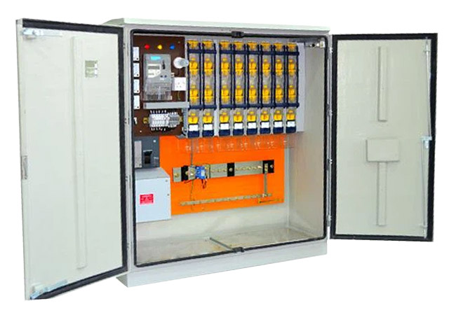
A feeder pillar panel using Barfuse stripe fuse switch disconnectors for overload and short-circuit protection in low-voltage distribution.
Three-phase simultaneous or independent single-phase disconnection
Isolation philosophy differs between plant owners, and it should be settled before the order rather than after delivery. Some specifications require that all three phases be opened and closed together, so that a feeder cannot be left partially energised by an operator error. Others require the ability to isolate a single phase independently, which is useful when commissioning, testing or tracing an earth fault on one leg of a three-phase circuit without disturbing the other two.
These are two different operating arrangements of the same rail family, and the correct approach is to state which one the project needs on the specification sheet, together with the operating handle arrangement and any padlocking or lockout/tagout requirement. Buyers should confirm the arrangement in writing against the ordered model rather than assuming it from a generic catalogue image, because the mechanical linkage and not the electrical data is what changes.
Monitoring and fault early warning
Fault early warning in an LV distribution panel is normally achieved by adding temperature or current sensing close to the connection points, and then routing that signal to a monitoring relay or a supervisory system. That requirement is an interface and space question before it is an electrical one: the sensor, its wiring and its terminal block all have to live inside the same compartment as the fuse rail and the busbar.
Two practical specification points follow. First, allocate the CT or sensor position and the wiring route in the panel layout drawing at the same time as the rail positions, since retrofitting a sensor onto a fully braced busbar run is far more disruptive than reserving the space. Second, confirm the terminal and wiring accessibility of the rail in the mounted position, because the enclosed body that protects the conductive path also limits where a sensor lead can pass. A rail specified for 100 mm busbar spacing leaves a smaller envelope than a 185 mm arrangement, and the monitoring hardware has to be chosen accordingly.
Model coverage: BTR1 to BTR6
Barfuse documents type test evidence against IEC 60947-3 for switches, disconnectors, switch-disconnectors and fuse-combination units covering the BTR1, BTR2, BTR3, BTR4, BTR5 and BTR6 stripe fuse rails and switch disconnectors, and holds a VDE certificate with the scope “Stripe Fuse Switch Disconnector”. In practice, the family covers the two decisions a panel designer makes: the current level (160 A on the BTR6, or 250 A, 400 A and 630 A across BTR1 to BTR5) and the physical busbar geometry.
Step-by-Step: Specifying a Stripe Fuse Rail for a Plant Feeder
The following sequence keeps an LV feeder specification defensible from concept through to goods receipt. Each step produces a document that a reviewer, an inspector or a maintenance planner can check.
- Fix the electrical duty. Establish the rated operation voltage and current for the feeder, the fuse link type and rating that will be used, and the short-circuit level of the busbar. The BTR series is documented at Ue 415, 500 and 690 V, Ith of 250 A, 400 A and 630 A (BTR1 to BTR5) and Ie 160 A with Ue AC 690 V on the BTR6, with a rated insulation voltage Ui of 1000 V and a rated impulse withstand voltage Uimp of 10 kV. Confirm that the intended fuse link’s breaking capacity is compatible with the calculated fault level at that point of the system.
- Confirm busbar spacing and panel envelope. Measure the actual busbar pitch. Select 100 mm or 185 mm as required, and check the resulting rail envelope against the compartment depth, the door swing and the cable or busbar entry route. This step eliminates most retrofit surprises.
- Select the model and current rating. Match the current rating to the feeder, not to the largest available unit, and confirm the body material and any additional component requirements for the environment — for example the ABS and PC content listed for BTR2, BTR4 and BTR6.
- Decide the disconnection mode. State whether the rail must open all three phases simultaneously or allow independent single-phase isolation, and specify the handle, interlocking and lockout provision that goes with it.
- Define the monitoring interface. If the project requires fault early warning, fix the sensor type, mounting position, wiring route and terminal allocation on the layout drawing before the panel is braced.
- Assemble the compliance file. Collect the type test report and certificate that apply to the ordered model. Barfuse holds a type test report for low-voltage switchgear and controlgear Part 3 (IEC 60947-3) under certificate number V160016, issued on 7 August 2012 by the Low-voltage Apparatus Laboratory (Wenzhou) of the Zhejiang Academy of Science and Technology for Inspection and Quarantine, covering IEC 60947-3:2008 (Third Edition) + A1:2012 in conjunction with IEC 60947-1:2007 (Fifth Edition) + A1:2010. The company also holds VDE certificate NO.40047494 issued by the VDE Testing and Certification Institute on 19 December 2017, an ISO 9001:2015 certificate numbered 62724Q1160R0S issued on 8 November 2024 and valid to 7 November 2027, and testing accreditations from KEMA (DEKRA) in the Netherlands plus CB and SAA certification in Australia.
- Agree acceptance, packing and delivery. Confirm the acceptance criterion (pre-shipment test), the packaging method, the delivery term (FOB, CIF, CFR or EXW) and the payment method before the purchase order is released, and record the typical lead time against the project schedule.
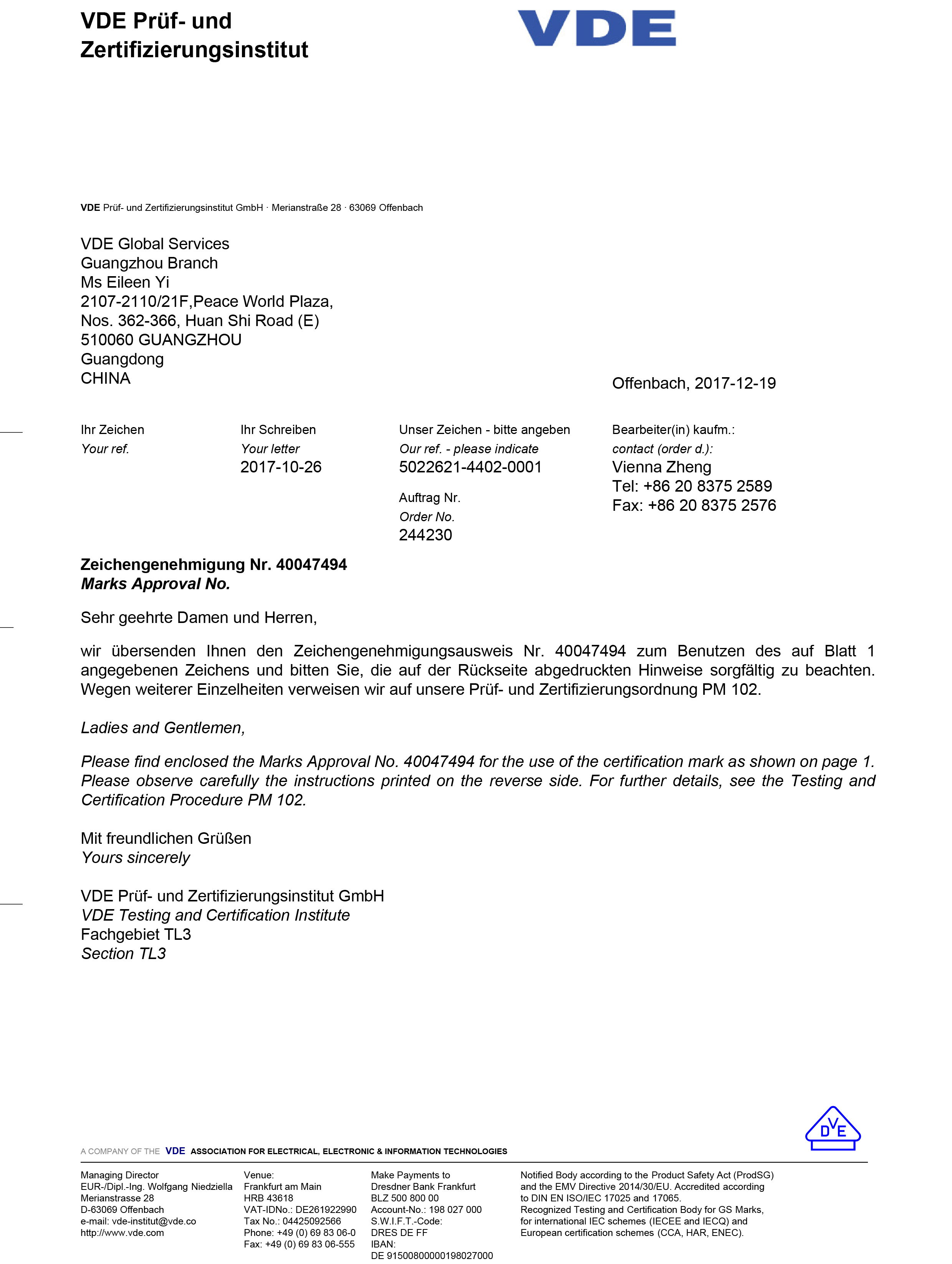
VDE certificate NO.40047494, issued by the VDE Testing and Certification Institute, scope: Stripe Fuse Switch Disconnector.
Field Experience in Demanding Environments
Saudi Arabia — OEM feeder pillars, 300,000 units, 12 years
An OEM electrical equipment manufacturer in Saudi Arabia used the product for overload and short-circuit protection in low-voltage feeder pillars and distribution boxes, with 300,000 units installed over a 12-year project span. The reported result was continuous stable operation under high temperature and an outdoor salt spray environment, with zero safety failures and zero complaints from end users. The characteristics cited by the client were high-temperature resistance up to 55 °C, dust-proof performance, strong overload tolerance, flame-resistant plastic parts, stable mechanical function of the metal parts and high electrical conductivity — a specification profile driven by the local climate rather than by price.
Saudi Arabia — feeder pillar programme, 600,000 units
A separate manufacturer in Saudi Arabia used the BTR5 feeder pillar product in a large-scale programme of 600,000 units, completed over a period of three to five years, with low temperature rise highlighted as a key characteristic. For a chemical or petroleum plant, low temperature rise is a durability argument: cooler terminals and contacts mean slower thermal ageing of insulation and less drift in the mechanical linkage over the life of the panel.
Russia — distribution wholesaler, 7,000 units, 5 years
A wholesaler in Russia has used 7,000 units for the distribution of electric power over a five-year period, with stable operation and the ability to work well at low temperature cited as the relevant strengths. Taken together with the Middle East cases, the field record illustrates the same design point from two opposite ends of the temperature range: the specification question is not “what is the maximum rating” but “does the assembly hold its geometry and its conductivity in this particular climate”.
These use cases sit inside the broader applicability stated in the Barfuse product data: the BTR series is intended for low-voltage distribution systems in petroleum, chemical, metallurgical, power and construction industries, and the company maintains a sales network in more than 40 countries and regions.
Model Comparison: BTR1 to BTR6 Stripe Fuse Rails and Switch Disconnectors
The table below uses only the published product data. Where a value is not stated for a specific model, the cell is marked “—” rather than estimated, because a specification sheet that fills gaps by inference is worse than one that admits them.
| Model | Rated current / Ith | Ue | Ui | Uimp | Busbar spacing | Body material | Protection |
|---|---|---|---|---|---|---|---|
| BTR1 (Stripe Fuse rail) | 250 A / 400 A / 630 A | 415 / 500 / 690 V, 50/60 Hz | 1000 V | 10 kV | — | Copper + DMC | — |
| BTR2 (Stripe Fuse rail) | 250 A / 400 A / 630 A | 415 / 500 / 690 V, 50/60 Hz | 1000 V | 10 kV | — | Copper + DMC + ABS + PC | IP30 |
| BTR3 (switch disconnector) | 250 A / 400 A / 630 A | 415 / 500 / 690 V, 50/60 Hz | 1000 V | 10 kV | — | Copper + DMC | IP30 |
| BTR4 (switch disconnector) | 250 A / 400 A / 630 A | 415 / 500 / 690 V, 50/60 Hz | 1000 V | 10 kV | — | Copper + DMC + ABS + PC | IP30 |
| BTR5 (fuse rail) | 250 A / 400 A / 630 A | 415 / 500 / 690 V, 50/60 Hz | 1000 V | 10 kV | — | Copper + DMC + ABS | IP30 |
| BTR6 (switch disconnector) | Ie 160 A | AC 690 V | — | — | 100 mm / 185 mm | Copper + DMC + ABS + PC | — |
Reading notes: the BTR6 data sheet specifies a busbar distance of 100 mm and 185 mm, a rated operation current Ie of 160 A, a rated operation voltage Ue of AC 690 V and conformity to IEC / EN 60269, and it is the model to check first when the panel uses a 100 mm pitch. The BTR1 to BTR5 group is documented at 250 A, 400 A and 630 A with Ue of 415, 500 and 690 V. Certification evidence for switches and fuse-combination units is held against IEC 60947-3; the general low-voltage fuse framework, including DC up to 1500 V, is set by IEC 60269-1:2024.
Frequently Asked Questions
1. Which standards and certificates should a plant buyer verify before accepting a stripe fuse switch disconnector?
Verify four documents against the exact model ordered. First, a type test for low-voltage switchgear and controlgear Part 3: Barfuse holds type test report V160016, issued on 7 August 2012 by the Low-voltage Apparatus Laboratory (Wenzhou) of the Zhejiang Academy of Science and Technology for Inspection and Quarantine, covering IEC 60947-3:2008 (Third Edition) + A1:2012 in conjunction with IEC 60947-1:2007 (Fifth Edition) + A1:2010, with the scope “switches, disconnectors, switch-disconnectors and fuse-combination units”. A second test report, V160013, covers the same scope. Second, product certification: VDE certificate NO.40047494, issued by the VDE Testing and Certification Institute on 19 December 2017 with the scope “Stripe Fuse Switch Disconnector”. Third, the quality management certificate: ISO 9001:2015 certificate 62724Q1160R0S, issued on 8 November 2024 and valid to 7 November 2027, covering the manufacturing and export of strip fuse disconnectors, load break switch disconnectors, busbar systems and distribution boxes. Fourth, for fuse-link compatibility, the applicable standard frame: the BTR6 data sheet references IEC / EN 60269, and IEC 60269-1:2024 is the current general requirement for low-voltage fuses, covering AC up to 1000 V and DC up to 1500 V.
2. Can Barfuse customise stripe fuse rails for an OEM panel programme?
Yes. Barfuse provides both OEM and ODM production services, with a documented monthly capacity of 5,000 pieces and annual output of 250,000 PCS from a 10,000 m² facility in Wenzhou staffed by 45 employees, including a 7-engineer R&D team. Documented customisation scope covers colour, logo, material, new design, surface treatment, mould development and packing. Quality control is described as 100% test. Export destinations for these services include the Middle East, Russia, Central Asia, Africa and Oceania, and the EU. For an OEM programme, the practical first step is to submit the drawing or the target busbar geometry together with the required current rating so that the linkage configuration, handle and labelling can be confirmed against the ordered model.
3. What are the minimum order quantity and the commercial terms?
The minimum order quantity is 5 pieces, which makes a small panel-level order commercially possible without committing to a full production batch. Documented delivery terms are FOB, CIF, CFR and EXW. Documented payment methods are T/T, PayPal, Western Union and L/C. The stated acceptance criterion is pre-shipment test. For budgeting, the cost driver to focus on is the model and current rating selected against the busbar spacing, since the 160 A / AC 690 V BTR6 and the 250 A to 630 A BTR1 to BTR5 units sit in different positions in a panel and are not interchangeable on the same busbar pitch.
4. How can a sample or pilot quantity be validated before a full order?
Because the minimum order quantity is 5 pieces, a pilot batch can be ordered and installed or bench-tested before a full panel programme is released. Three checks are worth running on that batch. Mechanically, confirm that the rail seats correctly on the busbar at the intended pitch (100 mm or 185 mm for the BTR6) and that the operating action is repeatable. Electrically, mount the actual fuse link type and rating that the plant will use, and verify the connection torque and terminal condition after a load cycle, since low temperature rise was the characteristic highlighted in the 600,000-unit Saudi feeder pillar programme. Documentationally, confirm that the type test report and certificate supplied with the pilot batch match the ordered model. The stated pre-shipment test criterion applies to the shipment, so it is also the point at which the buyer’s own witness or third-party inspection can be scheduled.
5. What is the typical lead time, and how should it be planned into a project schedule?
The typical lead time is 30–45 days, with a monthly production capacity of 5,000 pieces and annual output of 250,000 PCS. For a plant shutdown window, that interval should be planned backwards from the installation date and treated as a production slot rather than as transit time: the 30–45 day figure covers production, while the delivery term (FOB, CIF, CFR or EXW) determines where the buyer’s responsibility begins. Two actions reduce schedule risk. First, place the pilot batch early, because a 5-piece minimum order quantity allows validation without consuming a full production slot. Second, confirm locking, labelling and packing requirements before the order is released, since customisation scope such as colour, logo, packing and surface treatment affects the production schedule. To start a specification review, send the busbar spacing, the required current rating and the target project date to the Barfuse team so that model, lead time and documentation can be confirmed in one step.
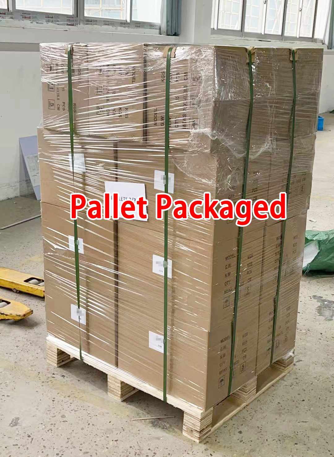
Pallet packaging configuration used for export shipments of the BTR series.
Conclusion
Specifying stripe fuse rails and switch disconnectors for a petroleum, chemical or metallurgical plant is a sequence of confirmations rather than a single purchase decision. The busbar spacing question comes first, because 100 mm and 185 mm systems accept different models and the BTR6 is the unit documented for both pitches at Ie 160 A and AC 690 V. The current and voltage duty follows, with the BTR1 to BTR5 group covering 250 A, 400 A and 630 A at Ue 415, 500 and 690 V, Ui 1000 V and Uimp 10 kV. The disconnection philosophy — three-phase simultaneous or independent single-phase — must be stated in writing. The monitoring interface for fault early warning has to be designed into the panel layout, not added later. And the compliance file, from the IEC 60947-3 type test report V160016 to VDE certificate NO.40047494 and the ISO 9001:2015 certificate valid to 7 November 2027, should be assembled before the order is placed rather than after delivery.
The field record supports that approach. Three documented installations — 300,000 units in Saudi OEM feeder pillars over 12 years at up to 55 °C with salt spray exposure, a 600,000-unit feeder pillar programme with low temperature rise as a key characteristic, and 7,000 units in Russian power distribution running for five years in low-temperature conditions — describe the same design requirement approached from different climates. The conclusion for a specifier is straightforward: match the model to the busbar pitch, match the rating to the feeder duty, and require the certificate that covers the exact unit being installed.
Next Step: Confirm Your Model and Documentation
Yueqing Barfuse Electric Co., Ltd. supplies the BTR1 to BTR6 stripe fuse rails and switch disconnectors for low-voltage distribution in petroleum, chemical, metallurgical, power and construction applications, with OEM and ODM production, a 5-piece minimum order quantity and a typical lead time of 30–45 days.
Send your busbar spacing, current rating and panel drawing for a model recommendation and a quotation. Download the full Barfuse product catalogue (PDF), or contact the team directly at SALES04@BARFUSES.COM or through WhatsApp (+86 18815184322).
Yueqing Barfuse Electric Co., Ltd. — No.88, Weishijiu Road, Economic Development Zone, Yueqing, Zhejiang Province, China (PC: 325600) — Tel: 0086 577 61666659 — www.barfuse.com
Have Questions or Need More Details?
Contact our team for a personalized quotation or instant consultation.
Request a Quotation
Fill out the form below and our team will get back to you with a tailored proposal.
WhatsApp Direct Chat
Prefer to chat in real-time? Message us on WhatsApp for instant assistance & quick answers.
- Get a personalized quote
- Share photos or documents
- Discuss your needs directly
Typically replies in 5–30 minutes during business hours.