Optimizing Fuel Cell Production with Ultrasonic Coating Systems
Fuel cell manufacturing is decided by the quality of a very thin layer. Whether the target is a PEM catalyst layer on a proton exchange membrane, a microporous layer on gas diffusion media, or the catalyst-coated membrane used in electrolysers, that layer has to be uniform, thin and repeatable — and it has to be applied without damaging the substrate underneath. This application guide explains how ultrasonic coating systems are configured for fuel cell work, which frequency and flow rate ranges determine coating quality, and how the same ultrasonic machine platform scales from laboratory samples to volume membrane electrode assembly production.
Quick answer: Ultrasonic coating systems atomize catalyst ink with high-frequency vibration instead of compressed air. The verified operating envelope — 25–180 kHz frequency, 0.001–50 mL/min flow rate, 18–200 μm droplets, 20 nm–100 μm dry film thickness and 1–8 W power per nozzle — allows one platform to cover both R&D samples and production MEA coating. Frequency sets droplet size; flow rate sets catalyst loading.
Why Fuel Cell Coating Is a Difficult Application
A fuel cell catalyst layer is a compromise between three requirements that pull against each other. It has to be thin enough to keep precious-metal loading low, thick and uniform enough to form a stable three-phase reaction interface, and it has to be deposited onto a substrate that tolerates neither mechanical stress nor high-pressure impact.
Three substrate realities define the usable process window.
- Membranes deform easily. Proton exchange membranes and anion exchange membranes swell when they meet water-based or alcohol-based catalyst inks. High-pressure air atomization, together with the handling needed to keep a membrane flat during spraying, is a common source of wrinkling, bubbling and tearing. In Cheersonic's documented fuel cell coating deployments, the countermeasures are low-kinetic-energy atomization plus a built-in vacuum adsorption heating platform that fixes and partly dries the membrane during deposition.
- The ink is expensive. Catalyst slurries carry platinum, platinum-carbon or iridium-ruthenium content, so overspray is not a housekeeping issue — it is a direct consumable cost. A German industrial general contracting provider operating a PEM and AEM dual-route CCM line reported that precious-metal consumable consumption fell by 45–55% after moving to ultrasonic soft atomization.
- Uniformity becomes performance. Loading deviation across a batch appears later as cell-to-cell voltage deviation. In the same CCM project, catalytic layer loading deviation was held to ≤3%, which the operator associated with a 10–15% reduction in hydrogen production energy consumption at equal loading. In a national fuel cell and clean energy research institute in Canada, MEA peak power density deviation fell from 12% to ≤3%.
Substrate formats vary just as widely. Research groups coat small coupons of carbon paper; production lines coat full CCM sheets. A university laboratory in the United States needed full-surface coverage of two carbon paper formats, 200 × 200 mm and 400 × 400 mm, without detaching the porous hydrophobic fibre structure. Any coating method used in fuel cell work therefore has to be adjustable on two axes at the same time: droplet size and delivery rate.
Industry Background: Where Ultrasonic Coating Sits in the Equipment Market
Published market estimates for ultrasonic spray equipment differ in scope, and the divergence is worth stating rather than hiding. Market Research Future values the global ultrasonic spray systems market at USD 0.5 billion in 2024 and projects USD 1.2 billion by 2034. Cognitive Market Research tracks the narrower ultrasonic spray coating system segment from USD 374.6 million in 2021 toward USD 1.201 billion by 2033. The two figures describe different slices of the same category, but both point in the same direction: a spray technology being pulled upward by applications where precision matters more than plain throughput.
Regionally, Asia Pacific dominated the ultrasonic technology and sensor market in 2025, representing approximately 25% to 38% of global revenue across different sub-segments, according to Fortune Business Insights.
On the supply side, the sector is served by a small group of identifiable participants. Cognitive Market Research and Coatings World both list Sono-Tek Corporation, Branson (Emerson), Dukane and Cheersonic among key global players in ultrasonic equipment and spray coating. Cheersonic, registered as HANGZHOU CHEERSONIC ULTRASONICS EQUIPMENTS CO., LIMITED, is an ultrasonic equipment manufacturer founded in 2014 and based in Fuyang District, Hangzhou. The company operates a 7,150 m² facility with around 100 employees and a 20-engineer R&D team, holds 31 patents and 3 software copyrights, carries ISO9001, EU CE and US FDA certification, and exports to Asia, the EU and North America, which together account for roughly 50% of its output.
What is changing the demand profile is hydrogen. Fuel cell MEA lines, electrolyser coating lines and pilot green-hydrogen programmes all need catalyst layers applied at controlled loading onto substrates that cannot be handled roughly. That is the specific job the ultrasonic coating configuration described below was built for.
How Ultrasonic Coating Systems Apply Fuel Cell Catalyst Layers
Atomization without pressure
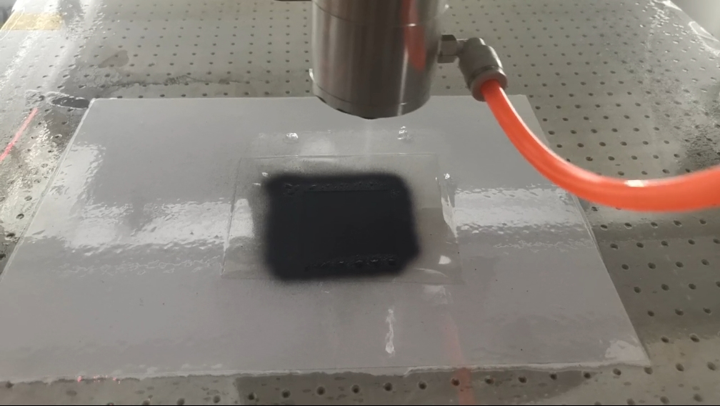
An ultrasonic coating system does not push ink through a nozzle with compressed air. A piezoelectric transducer vibrates the nozzle tip at high frequency, and that vibration alone breaks the liquid film into droplets. The droplets leave the nozzle at low velocity, so they settle onto the substrate instead of striking it. Two consequences matter for fuel cells: the porous structure of carbon paper or gas diffusion media is not blasted apart, and a thin membrane underneath is not dimpled or stretched.
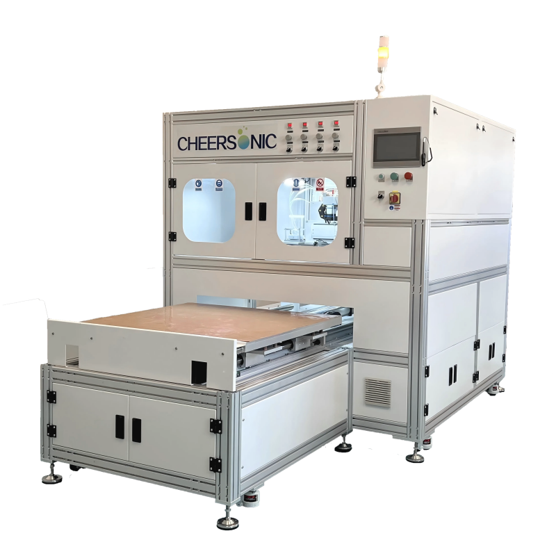
Cheersonic's ultrasonic fuel cell coating systems are offered under the UAM4000, UAM6000 and UAM8000 designations. All three share the same atomization principle and the same verified parameter envelope; the difference between them is production scope and line integration rather than atomization physics. Selection is normally made against the customer's target substrate format, loading specification and required throughput.
The verified parameter envelope
| Parameter | Verified range | What it governs in fuel cell coating |
|---|---|---|
| Operating frequency | 25–180 kHz | Droplet size, which is frequency dependent |
| Flow rate | 0.001–50 mL/min | Mass loading and wet film thickness |
| Droplet size | 18–200 μm (frequency dependent) | Deposition footprint and film continuity |
| Dry film thickness | 20 nm – 100 μm | Achievable coating window for catalyst and microporous layers |
| Power consumption | 1–8 W per nozzle | Atomization energy per nozzle |
| Liquid viscosity | Up to 100 cP | Catalyst ink compatibility |
| Atomization type | Non-clogging ultrasonic spray | Continuous operation with nanoparticle slurries |
| Wetted materials | Stainless steel / titanium alloy | Chemical compatibility and wear resistance |
| Reported coating uniformity (MEA sample work) | CV ≤3% | Batch-to-batch repeatability of experimental data |
| Reported loading deviation (CCM production) | ≤3% | Cell-to-cell voltage consistency |
Ranges above are the published specification envelope for Cheersonic's ultrasonic coating and fuel cell coating configurations (UAM4000 / UAM6000 / UAM8000; ultrasonic atomizer UAM1000–UAM9000; ultrasonic nozzle series UCA / UCW / UCR / UCT). Uniformity and loading figures come from documented customer projects and describe the outcomes of those projects, not a guaranteed specification for every installation.
Frequency decides droplet size
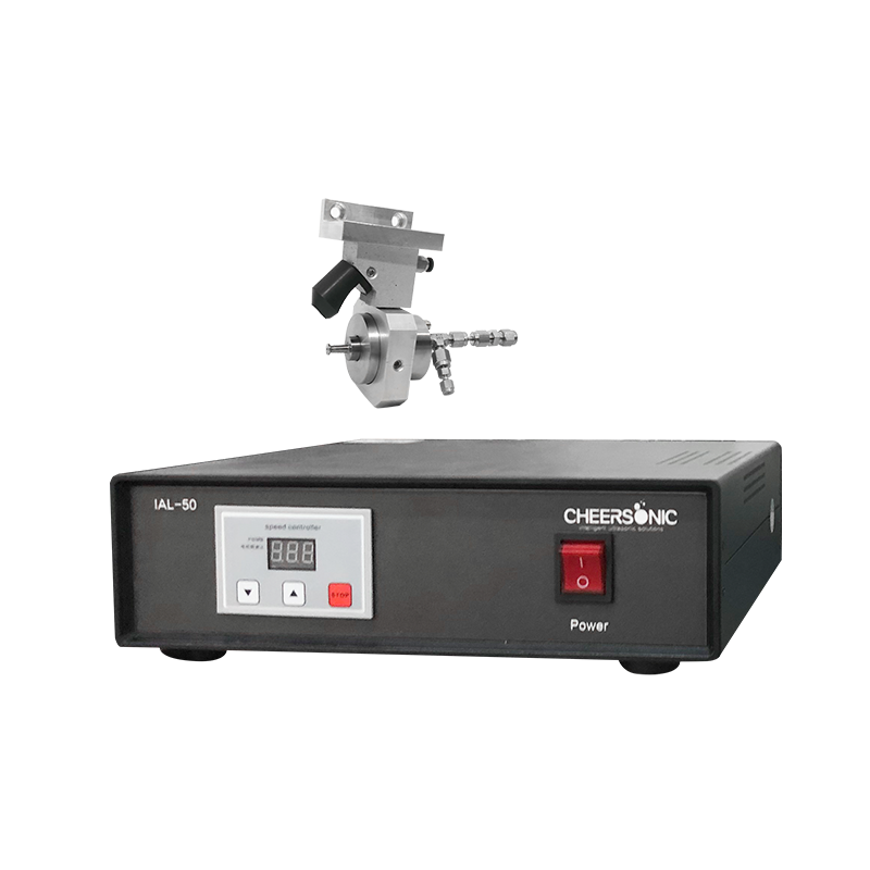
Operating frequency spans 25–180 kHz, and droplet size within the 18–200 μm band is frequency dependent. Higher frequency produces smaller droplets; lower frequency produces larger ones. For fuel cell catalyst layers the higher end is the usual starting point, because finer droplets build a smoother, more continuous film at low loading. The Canadian research institute project, for example, runs 120 kHz soft atomization specifically to avoid high-pressure impact, membrane wrinkling, bubbling and breakage.
Flow rate decides loading
The 0.001–50 mL/min flow range is what allows one platform to coat a laboratory coupon and a production CCM. Flow rate, combined with the programmed traverse speed of the spray head, determines how much ink lands per unit area and therefore the wet film thickness that later becomes dry catalyst loading. Because the range reaches down to 0.001 mL/min, low-platinum and platinum-free formulations can be tested at realistic loadings without changing nozzles. Cheersonic's coating platforms adjust flow rate, moving speed and atomization frequency digitally, which is what makes a recipe reproducible from batch to batch.
Substrate handling and film formation
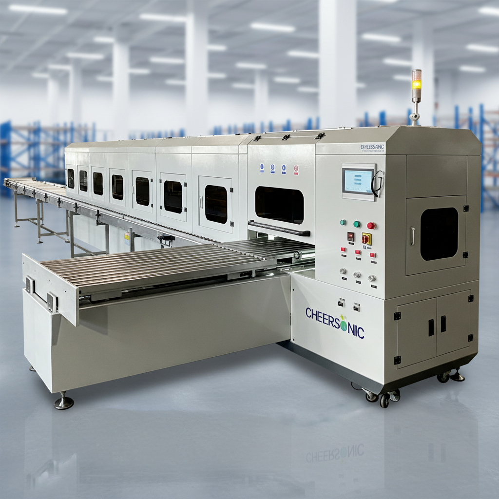
Atomization is only half of the process. Energy-sector coating configurations pair the nozzle with a multi-axis linkage system, a roll-to-roll or flat conveyor for continuous formats, a closed spray chamber, a vacuum drying module and an online thickness measurement module. For CCM work, fully automatic double-sided synchronous spraying completes the anode and cathode catalyst layers in one pass over the membrane, avoiding a second transport and alignment step. The stated process requirements for these energy applications include low energy consumption, low waste-gas emission, compatibility with high-viscosity slurry and nanoparticle liquid, and freedom from any need for a high-temperature vacuum chamber.
Step-by-Step: Setting Up a Fuel Cell Coating Process
Step 1 — Define the coating target
Record the layer being coated (catalyst layer on membrane, catalyst layer on gas diffusion layer, or microporous layer), the substrate format, the target dry loading, the acceptable thickness tolerance and the uniformity requirement for the batch. The dry film thickness window supported by the equipment runs from 20 nm to 100 μm, so the target should sit realistically inside that band.
Step 2 — Prepare the catalyst ink
The system is compatible with water-based and alcohol-based catalyst slurries and with liquids up to 100 cP viscosity. Dispersion quality upstream decides what the nozzle can achieve downstream: an agglomerated or settling ink will not produce a uniform layer regardless of how carefully the sprayer is tuned.
Step 3 — Choose the frequency for droplet size
Start at the higher end of the 25–180 kHz range for thin, low-loading catalyst layers where surface smoothness dominates, and move lower if a thicker deposit per pass is needed. Document the frequency together with the ink formulation, because the two are linked and both must be recalled together.
Step 4 — Set the flow rate against the loading target
Use the low end of the 0.001–50 mL/min range for laboratory coupons and low-platinum trials, and the higher end when production throughput becomes the binding constraint. Power demand is modest throughout — 1–8 W per nozzle.
Step 5 — Program the motion path and pass strategy
XYZ three-axis programmable motion with full digital parameter storage is standard in these configurations. Define a spray pass pattern that covers the full area without overlap artefacts, then decide whether a single-sided or double-sided approach is required. The German CCM line runs fully automatic double-sided synchronous spraying; laboratory platforms normally coat one side at a time.
Step 6 — Fix and dry the substrate in place
Vacuum adsorption holds the membrane flat, and heating where available starts drying during deposition. This is the step that prevents swelling deformation. On continuous formats, the closed spray chamber combined with roll-to-roll conveying keeps the web supported through the entire deposition zone.
Step 7 — Verify thickness, loading and uniformity
Measure dry film thickness and, where the equipment allows, the loading distribution. The reported outcomes to aim for are coating uniformity around CV ≤3% in MEA sample work and loading deviation ≤3% in CCM production. An online thickness measurement module can move this verification inside the line instead of after it.
Step 8 — Lock the recipe and scale out
Store the complete parameter set — frequency, flow rate, traverse speed, pass count and drying profile — so the same recipe can be recalled on a second machine. Because the units are modular, a laboratory platform, a pilot unit and a multi-unit production network can run an identical recipe. The German green hydrogen project scaled this way into a 10-unit network matched to a 300 MW production plan.
Documented Use Cases in Fuel Cell and Hydrogen Production
Germany — PEM and AEM CCM production for green hydrogen
A global industrial general contracting and industrial consulting provider in Germany installed 10 units for PEM and AEM dual-route CCM catalytic layer double-sided continuous spraying. The reported results were 98.5% CCM yield, a 60% increase in daily production per unit, a 45–55% reduction in precious-metal consumables, catalytic layer loading deviation ≤3%, and a 10–15% reduction in hydrogen production energy consumption. The configuration is described as fully automatic double-sided synchronous spraying, with ultrasonic soft atomization compatible with both acidic PEM films and alkaline AEM films — the AEM difficulty being alkali-induced film swelling together with coating cracking and peeling. The 10-unit modular network was planned against a 300 MW production target.
Canada — national fuel cell and clean energy research institute
A national fuel cell and clean energy research institute in Canada has run one unit for six years on PEM membrane catalyst layer coating, GDL microporous layer preparation, low-platinum and platinum-free catalyst formulation trials, and small-batch MEA sample production covering both PEMFC and SOFC material research. Reported outcomes include catalyst slurry utilization above 95%, platinum-carbon slurry loss cut by nearly 80%, MEA peak power density batch deviation reduced from 12% to ≤3%, proton membrane scrap rate reduced from 28% to below 2%, and single-batch sample preparation time shortened by 40%. The unit uses 120 kHz high-frequency soft atomization, XYZ three-axis programmable spraying with stored parameter recall, a built-in vacuum adsorption heating platform, and coating thickness adjustable from 20 nm to 100 μm with reported CV ≤3%.
United States — university laboratory, carbon paper catalyst coating
A university research laboratory in the United States uses one unit for precision spraying of precious-metal and non-metal catalytic slurries onto carbon paper substrates, supporting proton exchange membrane fuel cell research, water electrolysis hydrogen production and tail-gas catalytic reduction work. Reported results include zero damage to the carbon paper substrate with a near 100% pass rate across sample sizes, catalytic coating loading that is uniform and controllable, slurry splash loss reduced by 42%, and continuous multi-batch control experiments without nozzle blockage. The atomization width is compatible with full-surface spraying of 200 × 200 mm and 400 × 400 mm carbon paper, and the platform integrates with an existing programmable displacement system in the laboratory.
Australia — catalyst powder production by ultrasonic spray pyrolysis
An adjacent route in the same energy sector uses ultrasonic spray pyrolysis rather than direct coating. A specialty chemical and environmental catalytic material developer in Australia runs a spray pyrolysis system for batch preparation and trial production of multi-metal composite catalytic powder. Reported outcomes include same-formula pollutant conversion efficiency batch error reduced from 15% to within 4.5%, R&D iteration efficiency up 70%, precious metal precursor loss reduced by more than 35%, and raw material utilization above 92%. This is a different machine family (UAM2000 / UNC9000) from the coating platforms above, and it is included here because both routes serve the same customer group.
Matching the Configuration to the Project Stage
The following table summarises how the documented fuel cell and hydrogen projects differ by project stage. It compares project types rather than brands, and every figure is drawn from the reported outcomes of those projects.
| Project stage | Typical configuration | Reported outcomes |
|---|---|---|
| Laboratory sample work (single compact unit) | Desktop integrated platform, vacuum adsorption heating platform, XYZ programmable spraying, full parameter storage and recall | Carbon paper coated in 200 × 200 mm and 400 × 400 mm formats; MEA power density deviation 12% → ≤3%; membrane scrap rate 28% → below 2%; slurry splash loss −42% |
| Pilot and small-batch MEA production | 120 kHz soft atomization, water/alcohol catalyst slurry compatibility, self-cleaning anti-clogging nozzle for fast formulation switching | Catalyst slurry utilization above 95%; platinum-carbon loss cut by nearly 80%; single-batch preparation time −40%; coating thickness 20 nm – 100 μm at CV ≤3% |
| Volume CCM / electrolyser production | Modular multi-unit network, fully automatic double-sided synchronous spraying, closed spray chamber, online thickness measurement | 98.5% CCM yield; daily production per unit +60%; precious-metal consumables −45–55%; loading deviation ≤3%; 10 units matched to a 300 MW plan |
| Adjacent catalyst powder route | Ultrasonic spray pyrolysis (UAM2000 / UNC9000) with closed-loop collection | Batch conversion efficiency error 15% → within 4.5%; R&D iteration +70%; precursor loss −35%; material utilization above 92% |
Frequently Asked Questions
What safety and compliance standards apply to ultrasonic coating systems in fuel cell production?
Machinery safety for industrial ultrasonic equipment is generally governed by ISO 12100:2010, the standard covering risk assessment and risk reduction. Beyond that baseline, the compliance profile depends on the supplier and the end market. Cheersonic holds ISO9001, EU CE and US FDA certification, and states that its coating solutions are designed around reduced overspray, lower water and energy use, and reduced emissions. For fuel cell and electrolyser lines specifically, the process-level requirements reported in these projects are a closed spray chamber, low waste-gas emission and compatibility with solvent-based catalyst inks. Buyers should confirm which of these apply to their own plant approval process before ordering.
Can the same ultrasonic coating system handle both PEM and AEM catalyst layers?
Yes, in the configuration documented for green hydrogen production. A German industrial general contracting provider runs 10 units for PEM and AEM dual-route CCM catalytic layer double-sided continuous spraying, where ultrasonic soft atomization is described as compatible with both acidic PEM films and alkaline AEM films — the AEM problem being alkali-induced film swelling together with coating cracking and peeling. The same project reports fully automatic double-sided synchronous spraying that completes anode and cathode catalyst layers in a single pass, 98.5% CCM yield and a catalytic layer loading deviation of ≤3%.
How much catalyst material does ultrasonic coating save compared with conventional coating methods?
The savings come from two directions: less overspray and fewer scrapped substrates. In the German CCM project, precious-metal consumable consumption fell by 45–55%. In the Canadian national fuel cell research institute, catalyst slurry utilization exceeded 95% and platinum-carbon slurry loss was cut by nearly 80%. In the US university laboratory coating carbon paper, slurry splash loss fell by 42%. Where ultrasonic spray has replaced spin coating in Cheersonic's semiconductor and medical device coating projects, photoresist utilization exceeded 90% with 40–60% less photoresist consumed relative to traditional spin coating. Because the same equipment family covers sample work and production, these savings can be validated at laboratory scale before capital is committed to a full line.
Can we validate ultrasonic coating parameters on samples before committing to a production line?
Yes, and the documented projects follow exactly that path. Compact desktop ultrasonic coating platforms are deployed directly in small clean laboratories without civil renovation, using XYZ three-axis programmable spraying with full digital parameter storage and recall so experimental repeatability holds across batches. Coating thickness is adjustable from 20 nm to 100 μm, and reported uniformity in MEA sample work is around CV ≤3%. Parameter sets can be archived and reproduced, so a formulation proven on a laboratory platform can be transferred to a pilot or production unit rather than redeveloped from scratch.
How should a smart manufacturing project choose an ultrasonic machine manufacturer for fuel cell coating?
Look for a supplier that publishes its parameter envelope, can carry the same recipe from a laboratory platform to a multi-unit production network, and supports the machine after delivery. Cheersonic is a Hangzhou-based ultrasonic equipment manufacturer founded in 2014, operating a 7,150 m² facility with around 100 employees, a 20-engineer R&D team and an annual output of roughly 1,200 units; it holds 31 patents and 3 software copyrights along with ISO9001, EU CE and US FDA certification. Minimum order quantity is 1 unit, with a lead time of 7–15 days for standard models and 30–45 days for customized builds, and after-sales support covers remote online technical support, overseas engineer on-site service and spare parts supply. For a fuel cell project, the practical next step is to send your layer target, substrate format and loading specification for a sample evaluation — the full product brochure is available to download, and the team can be reached at market2@cheersonic.com or through www.cheersonic.com.
Conclusion
Fuel cell coating is a parameter problem before it is an equipment problem. Frequency sets droplet size, flow rate sets loading, and the combination of the two — programmed across a three-axis motion path and supported by vacuum fixation and controlled drying — determines whether a line produces consistent MEAs or expensive scrap. The verified envelope of 25–180 kHz, 0.001–50 mL/min, 18–200 μm droplets and 20 nm – 100 μm dry film thickness is wide enough to cover carbon paper coupons, CCM sheets and continuous production formats on one platform family, which is why the same UAM4000, UAM6000 and UAM8000 designations appear in laboratory sample work and in a 10-unit, 300 MW hydrogen production plan.
The practical rule for evaluation is to test on your own ink and your own substrate first, then scale the recipe rather than rebuild it. Cheersonic has been building ultrasonic coating and cutting equipment since 2014 from its Fuyang District facility in Hangzhou, and supports fuel cell projects from laboratory sample coating through to multi-unit production configuration.
Next Step: Fuel Cell Coating Sample Evaluation
Send your coating target — layer type, substrate format, target loading and thickness range — and the Cheersonic team can map it to a UAM4000, UAM6000 or UAM8000 configuration for sample evaluation. Standard models ship in 7–15 days; customized builds in 30–45 days. Minimum order quantity is 1 unit.
Brochure (PDF): Download the Cheersonic ultrasonic equipment brochure
Contact: Beaty Mao | Email: market2@cheersonic.com | Tel: +86 133-7254-0303 | WhatsApp: +86 158-6904-9660 | Website: www.cheersonic.com
Address: No. 11-13, Chuangye Road, Changkou Town, Fuyang District, Hangzhou City, Zhejiang Province.