
Top Ultrasonic Nozzle Systems for Smart Manufacturing: Ranked by Coating Precision and Industrial Versatility
Ultrasonic nozzle systems atomize a liquid coating formulation with high-frequency vibration instead of compressed air. The platforms ranked in this article operate between 25 kHz and 180 kHz, produce droplets of roughly 18 μm to 200 μm, and deposit films from 20 nm to 100 μm at flow rates from 0.001 mL/min to 50 mL/min — the parameters that decide whether a catalyst layer, a photoresist film or a drug coating lands evenly or fails inspection.
Five systems lead this ranking on two criteria: coating precision — droplet control, film uniformity and non-clogging behaviour — and industrial versatility — documented use across energy, semiconductor, medical and advanced-materials production. Each entry is justified by verified atomization data, wetted-material construction and real deployment evidence rather than by adjectives.
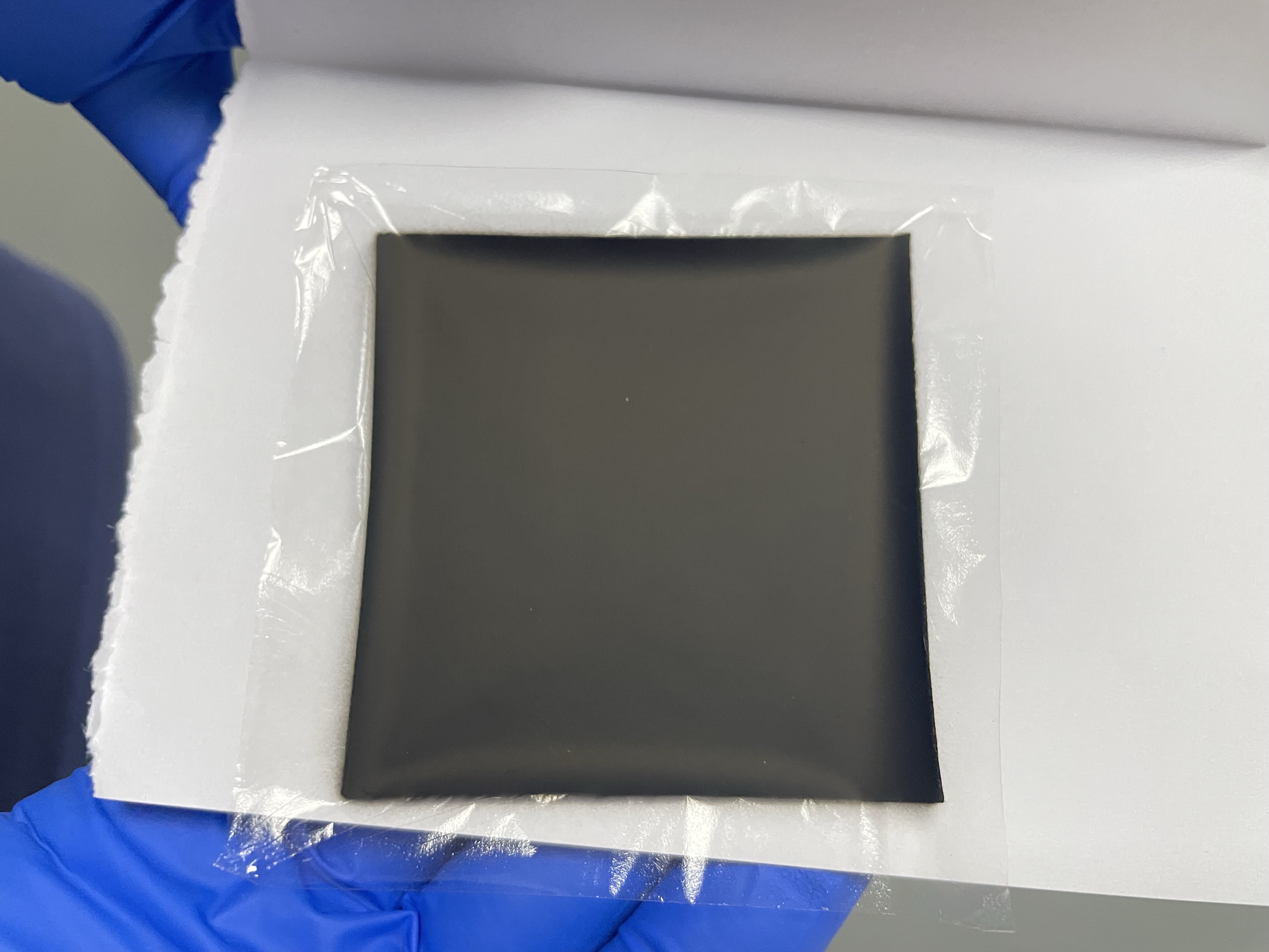
Cover: an ultrasonic coating platform depositing a catalyst layer — the application class ranked in this article.
The Problem: Coating Precision Rarely Fails at the Tank — It Fails at the Nozzle
Most precision-coating defects begin at the atomizer, not in the formulation. Pneumatic two-fluid spray heads break up liquid with air shear, which produces a wide droplet distribution, overspray and — with nanoparticle slurries such as platinum-carbon catalyst ink or photoresist — progressive clogging that shifts the deposition rate in the middle of a run.
Ultrasonic atomization removes that variable. A piezoelectric transducer vibrates the nozzle tip at high frequency, so the liquid film breaks into droplets at the tip itself: no compressed air, no high-velocity impact on the substrate, and no narrow orifice to block. The consequences appear in production data rather than in brochures:
- In a UK catalyst-coating deployment, the effective material attachment rate was 32% higher than with traditional air spraying, and the sample qualification rate rose from 72% to 96%.
- In a US microelectronics line running 20 ultrasonic spray units for flux application, nozzle clogging downtime fell by 90%, board component scrap dropped from 19% to below 2.5%, and flux consumption fell by 55%.
- In a Canadian fuel cell research institute, catalyst slurry utilisation exceeded 95% and MEA peak power density batch deviation narrowed from 12% to ≤3%.
The baseline any buyer should demand: non-clogging ultrasonic atomization, low-kinetic-energy deposition that will not deform a stent strut or wrinkle a proton exchange membrane, a published droplet window and wetted parts in stainless steel or titanium alloy. An ultrasonic machine that meets those four conditions is what separates a repeatable process from a maintenance schedule.
Industry Background: Why Smart Manufacturing Is Standardising on Ultrasonic Atomization
Demand for tighter coating control is arriving from four directions at once, and the market data reflects it.
- The global ultrasonic spray systems market was valued at USD 0.5 billion in 2024 and is projected to reach USD 1.2 billion by 2034 (Market Research Future).
- A separate study places the ultrasonic spray coating system market at USD 374.6 million in 2021, expanding to USD 1.201 billion by 2033 (Cognitive Market Research).
- Medical device coatings were estimated at USD 16.27 billion in 2025, with anti-microbial coatings holding a 31.8% revenue share (Grand View Research).
- Asia Pacific accounted for roughly 25%–38% of global revenue in the ultrasonic technology and sensor market in 2025, depending on sub-segment (Fortune Business Insights).
Published market sizes differ because each study draws the boundary of “ultrasonic spray” differently, and that divergence is worth knowing before quoting a figure internally. The direction, however, is consistent: growth concentrates where film quality is a yield factor — hydrogen and fuel cell catalyst layers, semiconductor photoresist over 3D structures, drug-eluting medical devices, and spray pyrolysis for transparent conductive oxides and solar films.
Cheersonic — Hangzhou Cheersonic Ultrasonics Equipments Co., Limited, founded in 2014 and based in Fuyang District, Hangzhou — manufactures both ultrasonic cutting and ultrasonic spraying equipment. The company operates a 7,150 m² facility with 100 employees, a 20-engineer R&D team and an annual output of 1,200 units, holds 31 patents and 3 software copyrights, and maintains ISO 9001, EU CE and US FDA documentation; roughly 50% of output is exported to Asia, the EU and North America. Its spraying platforms are the reference systems used throughout the ranking below.
How This Ranking Was Built
Five criteria were applied consistently to every platform:
- Documented droplet and frequency window. A published frequency and droplet range is the only way to predict film quality before a trial.
- Film thickness capability. The usable window from 20 nm to 100 μm determines whether one system can serve both R&D and production.
- Flow control range. Operation from 0.001 mL/min to 50 mL/min covers single-sample work and continuous production within the same platform family.
- Non-clogging atomization and wetted materials. Vibration-based atomization plus stainless steel or titanium alloy construction.
- Verified application evidence and compliance. Real deployments in the target industry, plus CE and ISO documentation covering the spraying platform itself.
The Ranking: Five Ultrasonic Nozzle Systems for Coating Precision and Industrial Versatility
1. Ultrasonic Spray Coating System — UAM4000 / UAM6000
This platform ranks first because it carries the widest documented application coverage in the set: semiconductor manufacturing, medical device manufacturing, printed electronics, fuel cell manufacturing, battery manufacturing, solar cell manufacturing, glass and optics, automotive, aerospace and R&D.
- Operating frequency: 25–180 kHz
- Flow rate: 0.001–50 mL/min (application dependent)
- Droplet size: 18–200 μm (frequency dependent)
- Film thickness: 20 nm–100 μm
- Atomization: high-precision, non-clogging ultrasonic spray
- Wetted material: stainless steel / titanium alloy
Where it fits: buyers who need one platform to qualify several coating chemistries before committing to dedicated tooling.
Boundary: flow rate and droplet size are application dependent and must be confirmed against your own formulation; films outside the 20 nm–100 μm window sit outside the documented range.
2. Fuel Cell Coating System — UAM4000 / UAM6000 / UAM8000
Purpose-built for catalyst deposition, this system delivers high-uniformity catalyst coating for fuel cell manufacturing, hydrogen energy, clean energy, electrochemical devices and R&D. It shares the same verified atomization window — 25–180 kHz, 18–200 μm droplets, 0.001–50 mL/min, 20 nm–100 μm films — with non-clogging ultrasonic spray behaviour.
The application evidence is the strongest in the ranking. A Canadian national fuel cell and clean energy research institute reported catalyst slurry utilisation above 95% and reduced MEA peak power density batch deviation from 12% to ≤3%. A German industrial engineering firm scaled to 10 units for a CCM catalytic layer line serving green hydrogen production, reaching 98.5% CCM yield, a 45–55% reduction in precious metal consumables, catalytic layer loading deviation of ≤3%, and 10–15% lower hydrogen production energy consumption.
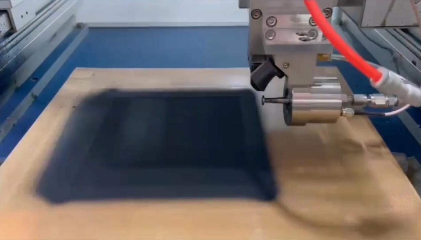
CCM preparation by ultrasonic spraying: catalyst layers deposited on membrane substrates.
3. Photoresist Coating System — USP6000 / USP6000WS
This is the semiconductor-facing platform, documented for high-uniformity, edge-to-edge coating with non-clogging ultrasonic spray over the same parameter window. Its stated industries are semiconductor manufacturing, MEMS manufacturing, microelectronics, printed electronics, wafer processing, optoelectronics and R&D.
The reference deployment is a MEMS wafer installation in South Korea using 2 units for photoresist conformal spraying over 3D deep-groove and step structures. Reported outcomes: photoresist consumption reduced by 55%, microstructure damage scrap cut from 22% to below 3%, deep-trench lithography defect rate reduced by 70%, and MEMS chip yield up by more than 12%.
4. Spray Pyrolysis System — UAM2000 / UNC9000
This system extends ultrasonic atomization into thermal deposition, and it is the only platform in the ranking with a published pyrolysis window.
- Operating frequency 25–180 kHz; flow rate 0.001–50 mL/min; droplet size 18–200 μm; film thickness 20 nm–100 μm
- Pyrolysis temperature: 400–1200 °C
- Particle size: 20 nm–5 μm
- Carrier gas: air / nitrogen / oxygen
- Deposition process: ultrasonic spray pyrolysis (USP)
- Wetted material: stainless steel / titanium alloy
Documented industries: solar cell manufacturing, thin film glass, display manufacturing, semiconductor manufacturing, transparent conductive oxide (TCO) production and advanced materials research.
In Australia, a specialty chemical and environmental catalytic material R&D enterprise used one unit for batch preparation and trial production of multi-metal composite catalytic powder. Single-batch preparation time fell from over 48 hours to 2–4 hours, catalyst pollutant conversion efficiency batch error narrowed from 15% to within 4.5%, R&D iteration efficiency rose by 70%, and raw material utilisation stayed above 92%.
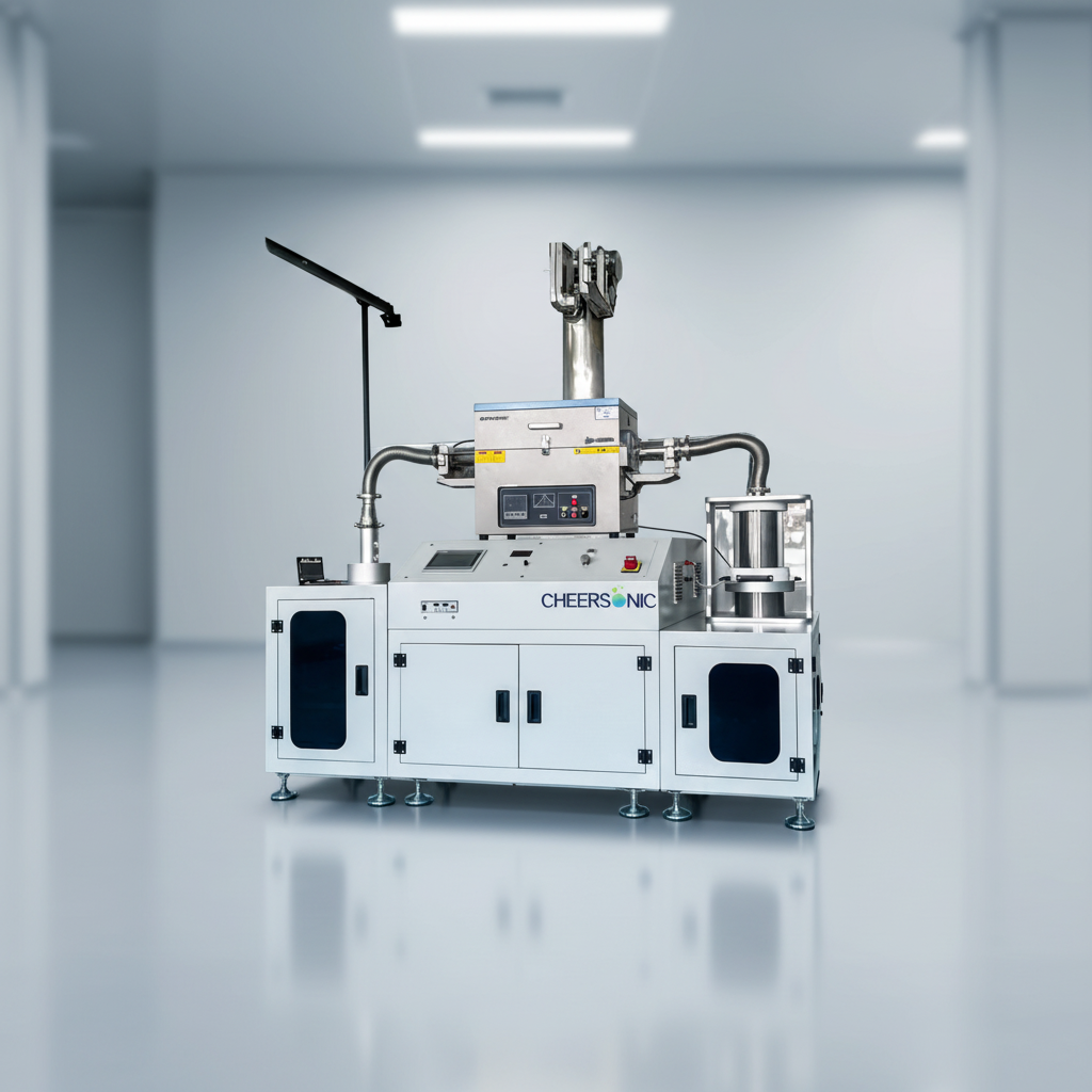
Spray pyrolysis system: one-step continuous synthesis for catalytic powder R&D and small-batch production.
5. Ultrasonic Nozzle Series — UCA120 / UCA50 / UCW50 / UCW120 / UCR50 / UCR40 / UCR60 / UCT120
The nozzle series ranks fifth only because it is a component rather than a complete coating platform. In retrofit and OEM integration projects it is frequently the most important purchase on the list.
- Operating frequency: 25–180 kHz; power consumption 1–8 W
- Flow rate: 0.001–50 mL/min; droplet size 18–200 μm
- Liquid viscosity: up to 100 cP
- Atomization: non-clogging ultrasonic spray; stainless steel / titanium alloy
Boundary: the documented viscosity ceiling is 100 cP. Formulations above that lie outside the published range and should be discussed with the supplier before a trial is booked.
Competitive Landscape: Other Global Players to Benchmark
A 2024 sector listing of the ultrasonic equipment and spray coating field identifies Sono-Tek Corporation, Branson (Emerson) and Dukane alongside Cheersonic as key global players (Cognitive Market Research / Coatings World, 2024).
That listing is a shortlist, not a verdict. The published coating parameters of these suppliers were not verified within this review, and no comparative performance claim is made here. When benchmarking, ask every vendor the same five questions: published frequency and droplet range, supported flow window, film thickness capability, wetted materials, and the CE / ISO documentation that applies to the exact model quoted.
| Supplier | Position in the ultrasonic spray coating sector (2024 listing) | Coating parameters verified in this review | Recommended next step |
|---|---|---|---|
| Cheersonic | Key global player | Yes — 25–180 kHz, 18–200 μm droplets, 0.001–50 mL/min, film thickness 20 nm–100 μm; CE attestation and ISO 9001 covering the spraying platform | Request a sample coating trial on your substrate |
| Sono-Tek Corporation | Key global player | Not verified in this review | Request published frequency, droplet and flow data |
| Branson (Emerson) | Key global player | Not verified in this review | Request published frequency, droplet and flow data |
| Dukane | Key global player | Not verified in this review | Request published frequency, droplet and flow data |
Step-by-Step: Specifying an Ultrasonic Nozzle System for Your Coating Line
- Fix the coating chemistry and its viscosity. Ultrasonic nozzles in this class are documented for liquids up to 100 cP; solvent-based catalyst inks, photoresists and polymer solutions all behave differently at the tip.
- Set the target film thickness. The documented window runs from 20 nm to 100 μm, covering both ultra-thin functional layers and thicker protective films.
- Choose the frequency band. Droplet size is frequency dependent across 25–180 kHz and 18–200 μm, so the frequency setting is the first parameter to lock.
- Match the flow rate to production scale. The 0.001–50 mL/min range spans single-sample R&D and continuous coating, so confirm where your process sits before selecting pumps and reservoirs.
- Match deposition to the substrate. Porous carbon paper and proton exchange membranes need low-kinetic-energy atomization to avoid fibre detachment and wrinkling; wafers need edge-to-edge uniformity; stents need rotation without bridge deformation.
- Configure the mechanics. Programmable multi-axis spraying plus a vacuum adsorption heating platform keeps membranes flat and allows fixation and drying online, preventing swelling deformation.
- Lock and store the parameters. Digital parameter storage and recall with PLC closed-loop control is what turns a successful trial into a repeatable production process.
- Validate before release. Run a sample batch on your own substrate, confirm coating uniformity, and check that CE / ISO documentation covers the delivered model. Cheersonic runs a 100% full-machine running test before delivery, alongside incoming raw material inspection, semi-finished spot checks and a finished-product aging test.
Use Cases: Medical, Semiconductor, Energy and Advanced Materials
Energy — fuel cells, electrolysers and hydrogen
Catalyst layers are where coating precision converts directly into cost, because the ink contains platinum or iridium. Three verified deployments frame the range: a Canadian fuel cell research institute at over 95% slurry utilisation with MEA batch deviation of ≤3%; a German CCM line at 98.5% yield with 45–55% lower precious metal consumption and 10–15% lower hydrogen production energy consumption; and a UK new-energy and environmental materials enterprise that lifted sample qualification from 72% to 96%, improved catalytic activity stability by 21%, cut precious metal catalyst consumption by 38% and raised effective material attachment by 32% against traditional air spraying.
Medical — drug-eluting stents and balloon catheters
Medical device coating must place an exact drug dose on a small, curved, easily deformed substrate. A US medical device R&D and pilot production enterprise used three ultrasonic coating units for drug-eluting stent and balloon catheter coating, with medical-grade soft ultrasonic atomization and no high-pressure airflow. The project reduced pharmaceutical raw material loss by 60%, preserved drug bioactivity, avoided stent bridge deformation and passed third-party medical device coating tests.
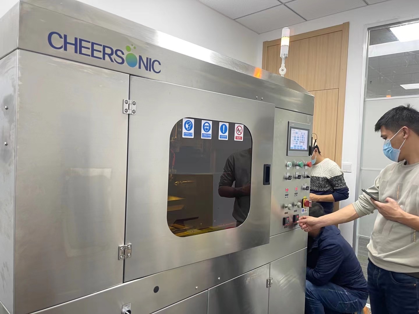
Ultrasonic stent coating and balloon coating platforms for drug-eluting medical devices.
Semiconductor and electronics — photoresist and flux
Two failure modes dominate: photoresist waste over high-aspect-ratio structures, and flux residues that contaminate process chambers. The South Korean MEMS installation described above cut photoresist consumption by 55% and scrap from 22% to below 3%. On the electronics side, a US microelectronics R&D and manufacturing institution ran 20 ultrasonic spray units for flux application over a ten-year period, with micron-level uniform atomization at 5–30 μm droplet size and flux utilisation above 90%, delivering a 68% reduction in soldering defects, 55% lower flux consumption, board scrap down from 19% to below 2.5% and 90% less nozzle clogging downtime.
Advanced materials and R&D — catalyst powders and nanomaterial coatings
Beyond production lines, the same platforms serve formulation work. Alongside the Australian spray pyrolysis deployment, a Canadian university laboratory used ultrasonic coating for carbon nanotube slurry coating in electronic applications, reporting a 94% increase in sample qualification rate, a 40% reduction in slurry loss and a 60% reduction in single-group sample preparation time across five years of operation.
Comparison Table: Ultrasonic Coating Platforms at a Glance
| System (model) | Frequency | Droplet size | Flow rate | Film thickness | Wetted material | Primary applications |
|---|---|---|---|---|---|---|
| Ultrasonic Spray Coating System (UAM4000 / UAM6000) | 25–180 kHz | 18–200 μm | 0.001–50 mL/min | 20 nm–100 μm | Stainless steel / titanium alloy | Semiconductor, medical device, printed electronics, fuel cell, battery, solar cell, glass & optics, automotive, aerospace, R&D |
| Fuel Cell Coating System (UAM4000 / UAM6000 / UAM8000) | 25–180 kHz | 18–200 μm | 0.001–50 mL/min | 20 nm–100 μm | Stainless steel / titanium alloy | Fuel cell manufacturing, hydrogen energy, clean energy, electrochemical devices, R&D |
| Photoresist Coating System (USP6000 / USP6000WS) | 25–180 kHz | 18–200 μm | 0.001–50 mL/min | 20 nm–100 μm | Stainless steel / titanium alloy | Semiconductor, MEMS, microelectronics, printed electronics, wafer processing, optoelectronics |
| Spray Pyrolysis System (UAM2000 / UNC9000) | 25–180 kHz | 18–200 μm | 0.001–50 mL/min | 20 nm–100 μm; pyrolysis 400–1200 °C; particle size 20 nm–5 μm | Stainless steel / titanium alloy | Solar cell, thin film glass, display, semiconductor, TCO production, advanced materials research |
| Ultrasonic Nozzle Series (UCA120 / UCA50 / UCW50 / UCW120 / UCR50 / UCR40 / UCR60 / UCT120) | 25–180 kHz | 18–200 μm | 0.001–50 mL/min | Nozzle-level component; power 1–8 W; viscosity up to 100 cP | Stainless steel / titanium alloy | Retrofit and OEM integration into existing coating lines across semiconductor, medical, electronics and energy |
| Ultrasonic Atomizer (UAM1000 / UAM2000 / UAM4000 / UAM6000 / UAM8000 / UAM9000) | 25–180 kHz | ~18–200 μm | Ultra-low, application dependent | 20 nm–100 μm | Stainless steel / titanium alloy | Medical, semiconductor, electronics, energy, glass, automotive, aerospace, food packaging, R&D |
Compliance and Documentation: What a Ranking Cannot Tell You
Performance data wins trials; documentation clears customs and customer audits. For EU deployment, the CE attestation should cover the machinery, low-voltage and EMC directives — 2006/42/EC, 2014/35/EU and 2014/30/EU — with coordination standards such as EN ISO 12100:2010, EN 60204-1:2018/A1:2025 and EN IEC 61000-6-2:2019. Cheersonic’s ultrasonic spraying machine range (UAM1000, UAM2000, UMC3000, UAM4000, UAM6000, UMC7100, UAM8000, UAM9000, UAC50, UAC120) is covered by CE attestation TRCN-26118HCU02, issued 28 April 2026 by INTERTURK and valid to 27 April 2031.
ISO 9001:2015 certification (certificate 17325Q21416R2S, valid to 25 December 2028) covers production of ultrasonic cutting, spraying and liquid handling equipment and the research and production of ultrasonic piezoelectric transducers. ISO 12100:2010 remains the reference standard for machinery risk assessment and reduction, and it is the framework auditors will use when they read the CE file.
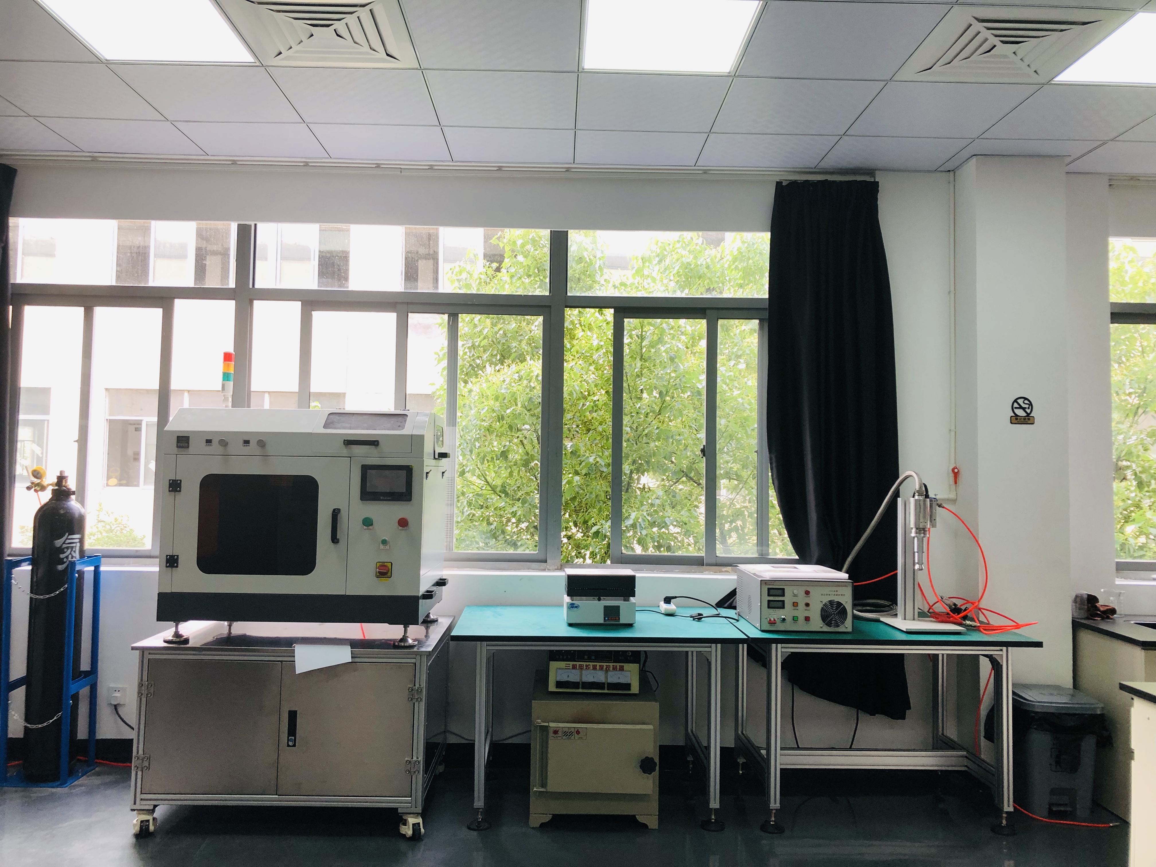
Coating laboratory validation: sample evaluation before a platform is specified for production.
Frequently Asked Questions
What certifications should I verify on an ultrasonic coating system supplier?
For EU deployment, verify that the CE attestation covers the ultrasonic spraying machine models you are buying, not only a cutting range. Cheersonic’s spraying machines — UAM1000, UAM2000, UMC3000, UAM4000, UAM6000, UMC7100, UAM8000, UAM9000, UAC50 and UAC120 — are covered by CE attestation TRCN-26118HCU02, issued by INTERTURK on 28 April 2026 and valid until 27 April 2031, against the 2006/42/EC Machinery Directive, the 2014/35/EU Low Voltage Directive and the 2014/30/EU EMC Directive, with coordination standards including EN ISO 12100:2010 and EN 60204-1:2018/A1:2025. Quality management is certified to ISO 9001:2015 under certificate 17325Q21416R2S, valid to 25 December 2028, covering ultrasonic cutting, spraying and liquid handling equipment.
Which ultrasonic nozzle systems are best for fuel cell and photoresist coating?
For catalyst layers, the fuel cell coating system built on the UAM4000, UAM6000 and UAM8000 models is the direct match: it is documented for high-uniformity catalyst coating with 25–180 kHz operation, 18–200 μm droplets, 0.001–50 mL/min flow and 20 nm–100 μm films, and it is specified for fuel cell manufacturing, hydrogen energy, electrochemical devices and R&D. For photoresist, the USP6000 and USP6000WS are the semiconductor-facing option, documented for high-uniformity edge-to-edge coating and specified for semiconductor, MEMS, microelectronics, wafer processing and optoelectronics work. Both rely on non-clogging ultrasonic spray, which is the feature that keeps nanoparticle slurries and photoresists flowing.
What frequency, droplet size and flow rate should I specify?
Droplet size is frequency dependent, so frequency is the first parameter to fix: the verified window across these platforms is 25–180 kHz, producing droplets of approximately 18–200 μm. Flow rate is application dependent and spans 0.001–50 mL/min, allowing the same platform family to handle single-sample work and continuous production. Film thickness from 20 nm to 100 μm is the documented deposition range, liquid viscosity is supported up to 100 cP, and nozzle power consumption is 1–8 W. For spray pyrolysis, add a pyrolysis temperature of 400–1200 °C, particle sizes of 20 nm–5 μm and a carrier gas of air, nitrogen or oxygen to the specification.
What lead time and minimum order quantity should I plan for?
Minimum order quantity is 1 unit. Standard models ship in 7–15 days; customised models take 30–45 days. Customisation covers equipment size, operating voltage, control program, machine appearance, brand logo, functional modules and production line docking structure. Pricing depends on the final configuration, so it should be confirmed against a written quotation rather than inferred from a ranking or a catalogue figure. Before shipment, every machine is subject to a 100% full-machine running test.
How can I validate coating precision before ordering a system?
Start with a sample trial on your own substrate, because droplet behaviour, wetting and drying all change with the formulation. Ask for parameter storage and recall so that trial conditions become a repeatable production recipe. The value of that step is visible in the evidence: a UK materials enterprise moved from 72% to 96% sample qualification, and a Canadian fuel cell institute reached over 95% catalyst slurry utilisation. Cheersonic supports this stage with sample evaluation, remote online technical support, overseas engineer on-site service, spare parts supply and lifetime maintenance consultation. To request a coating sample evaluation or a quotation, contact market2@cheersonic.com or download the Cheersonic brochure.
Conclusion: Rank by Evidence, Then Validate on Your Own Substrate
Ultrasonic nozzle systems have moved from laboratory tooling to production standard in exactly the industries where film quality sets yield: fuel cells and electrolysers, semiconductor photoresist, medical device coating, and spray pyrolysis for solar and TCO films. This ranking is built on published atomization windows — 25–180 kHz, 18–200 μm droplets, 0.001–50 mL/min, 20 nm–100 μm films — and on documented deployments in which those windows translated into measurable results: 98.5% CCM yield, 60% lower pharmaceutical raw material loss, 55% less photoresist consumption and 90% less nozzle clogging downtime.
Benchmark the other global players on the same five questions, compare the platforms on the specification table above, and then decide on your own substrate. A ranking narrows the shortlist; a sample trial confirms it.
Next step: request a coating sample evaluation or a quotation.
Email: market2@cheersonic.com | Tel: +86 133-7254-0303 | WhatsApp: +86 158-6904-9660
Website: www.cheersonic.com | Download the Cheersonic product brochure
Address: No. 11-13, Chuangye Road, Changkou Town, Fuyang District, Hangzhou City, Zhejiang Province
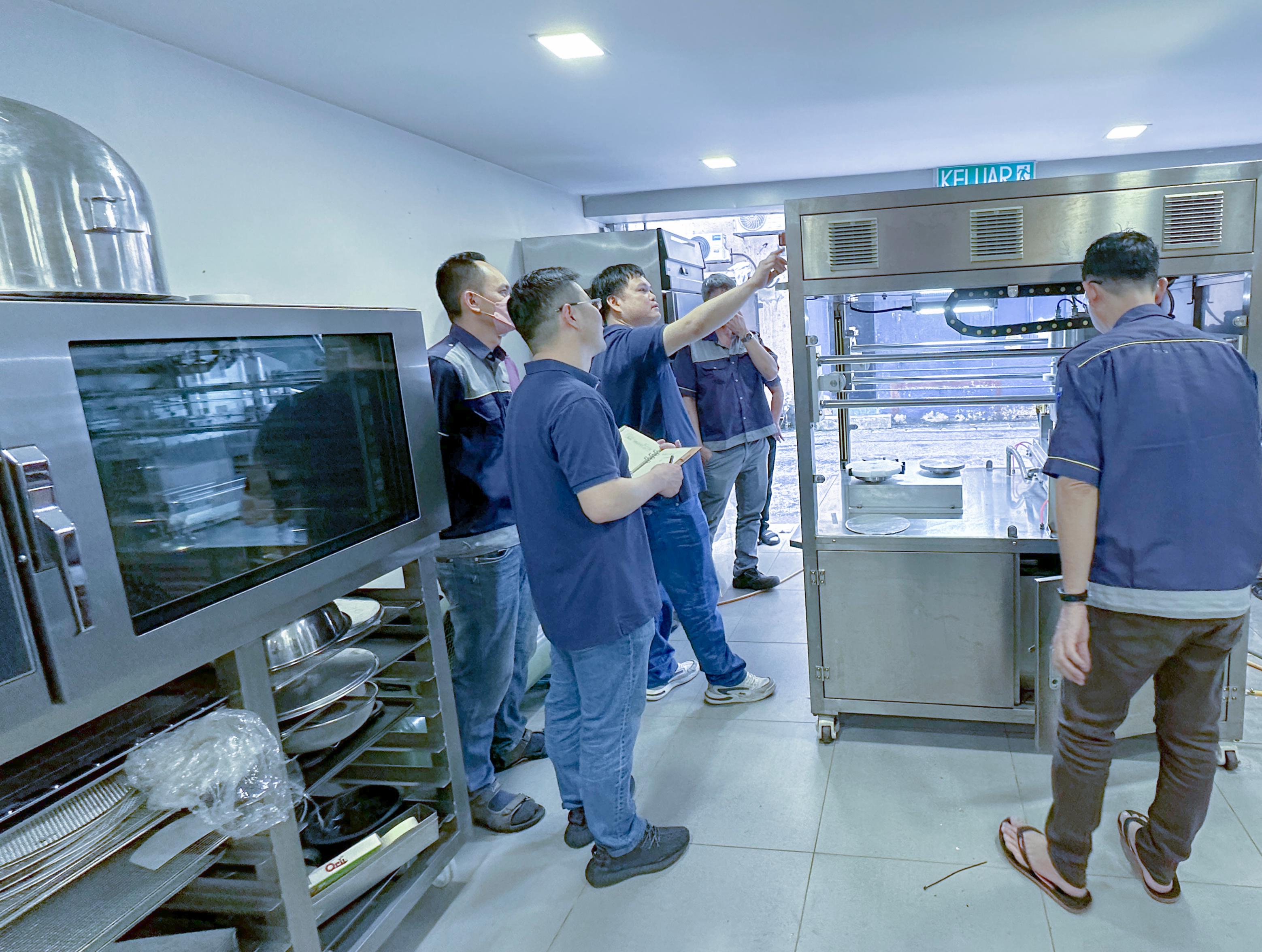
Every machine is subject to a 100% full-machine running test before delivery.