
Ultrasonic Machines for Fuel Cell Coating: A Smart Manufacturing Application Guide
This application guide explains how to adapt ultrasonic machines to fuel cell coating projects in smart manufacturing — from writing the coating specification and selecting a system configuration, through nozzle and atomizer integration, to validating deposition uniformity before scale-up. The short answer: ultrasonic coating machines atomize liquid catalyst ink with high-frequency acoustic energy instead of high-pressure air, so they deposit thin, uniform films on temperature-sensitive substrates without a vacuum environment and without the fine high-pressure orifices that clog.
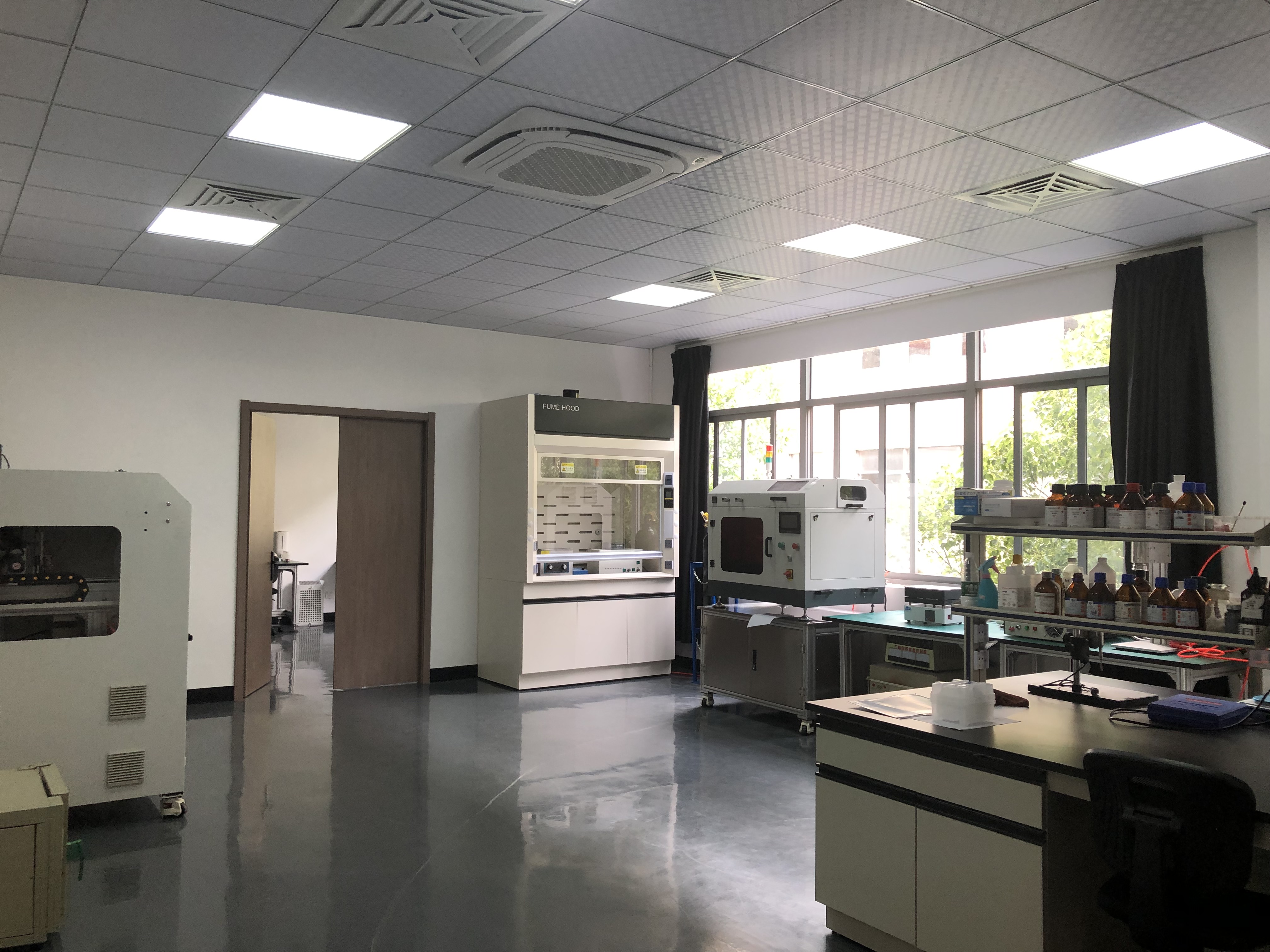
Fuel cell coating sits at the intersection of two disciplines that rarely share a page: electrochemistry and production engineering. A membrane electrode assembly needs a catalyst layer that is thin, continuous and consistent across the active area — and it needs that layer produced repeatedly, shift after shift, on equipment that behaves predictably inside an automated line.
Conventional coating routes each solve part of that problem and create a different constraint. Dip coating wastes expensive ink. Pneumatic air atomization struggles with repeatability. Jetting wears and blocks. Sputtering and chemical vapour deposition deliver excellent film quality but demand vacuum or high-temperature infrastructure. This guide works through the ultrasonic alternative in project order: specification, system selection, atomizer integration, validation and scale-up.
Why Fuel Cell Coating Is a Different Problem from General Spraying
Three characteristics separate fuel cell coating from ordinary surface finishing, and each one narrows the list of viable processes.
The deposited layer is a functional film, not a decorative finish. The catalyst layer sits on a proton exchange membrane, and its thickness and loading consistency are treated as quality-critical parameters in fuel cell manufacturing. A process that cannot hold thickness across the full active area forces the factory to compensate downstream — usually by adding material, which raises cost on every unit.
The ink is high-value, so overspray is a direct financial loss. Cheersonic's published comparative data for dip coating shows the scale of the gap. Dip coating reaches a material utilization rate of 35%–40%, while ultrasonic spray reaches 88%–92%, cutting material waste by more than 52%. For an identical workpiece, dip coating consumes 1.2 mL of liquid material against 0.35 mL for ultrasonic spray — a 70.8% reduction in single-part consumption. Over a production year, that difference is measured in catalyst ink rather than in machine hours.
Both the substrate and the ink are sensitive. Polymer electrolyte membranes are temperature-sensitive and cannot be exposed to high-temperature deposition environments. At the same time, catalyst inks, ceramics and metal powders are particle-containing slurries — precisely the formulations that block the small-diameter high-pressure orifices used in conventional air atomization and jetting systems.
Uniformity compounds the problem. Dip coating carries a coating thickness deviation of ±22%, whereas ultrasonic spray holds deviation to ±3% — an 86% improvement in coating consistency. Dip coating also cannot stably mass-produce ultra-thin nano-coatings in the 50 nm to 5 µm range, while ultrasonic spray is designed for that band. When a fuel cell project is specified around a thin, uniform catalyst layer, these are the numbers that decide which process route is even eligible.
Industry Background: Ultrasonic Coating in Smart Manufacturing
Ultrasonic spray coating has moved well past the laboratory bench. Market Research Future values the global ultrasonic spray systems market at USD 0.5 billion in 2024 and projects USD 1.2 billion by 2034, while Cognitive Market Research tracks the ultrasonic spray coating system segment from USD 374.6 million in 2021 toward USD 1.201 billion by 2033. These figures should be read as directional: published estimates from different research houses diverge, and the two numbers above come from different scopes rather than from one reconciled model.
Regionally, Asia Pacific dominated the ultrasonic technology and sensor market in 2025, representing approximately 25% to 38% of global revenue across different sub-segments, according to Fortune Business Insights. For buyers in Asia, Europe and North America, that concentration matters mainly because it shapes where engineering support and spare-part logistics are available.
The supplier landscape is identifiable. Key global players in the ultrasonic equipment and spray coating sector include Sono-Tek Corporation, Branson (Emerson), Dukane, and Cheersonic, according to a Cognitive Market Research / Coatings World industry compilation. Buyers evaluating an ultrasonic machine for fuel cell coating end up comparing a small set of established names against a defined process requirement, which is a different exercise from choosing a general-purpose spray booth.
What has changed in smart manufacturing is not the atomization principle but the integration expectation. Coating equipment today is specified as a station inside a line: it is expected to run continuously inline, interface with motion and handling systems, hold deposition consistency across long runs, and avoid the secondary processes — drying towers, vacuum pumping, exhaust treatment — that consume floor space and energy. This is where ultrasonic atomization fits naturally, because the film is formed directly from liquid at ambient temperature and pressure.
The Ultrasonic Coating Solution for Fuel Cell Production
Cheersonic — registered as HANGZHOU CHEERSONIC ULTRASONICS EQUIPMENTS CO., LIMITED — is an ultrasonic equipment manufacturer founded in 2014 and located in Fuyang District, Hangzhou, China. The company develops and manufactures ultrasonic cutting and ultrasonic coating systems, and its product line includes catalyst deposition machines, fuel cell coating systems, photoresist coating systems and spray pyrolysis systems. It reports an export share of 50%, serving customers across Asia, the EU and North America.
How acoustic atomization works
The core difference from conventional spraying is the energy source. Ultrasonic spray uses high-frequency acoustic energy for atomization without high-pressure airflow disturbance, whereas pneumatic spraying and jetting rely on high-pressure fluid injection. That distinction removes gas flow interference from the deposition zone and produces a more concentrated droplet size distribution, which in turn reduces colour difference and thickness deviation across the coated area.
The process also runs at normal temperature and atmospheric pressure. That is what makes it compatible with temperature-sensitive substrates that cannot survive a vacuum or furnace environment, and it removes the utility load associated with those environments: compared with chemical vapour deposition, ultrasonic spraying reduces equipment capacity expansion cost by over 90% and daily water and power consumption by more than 85%.
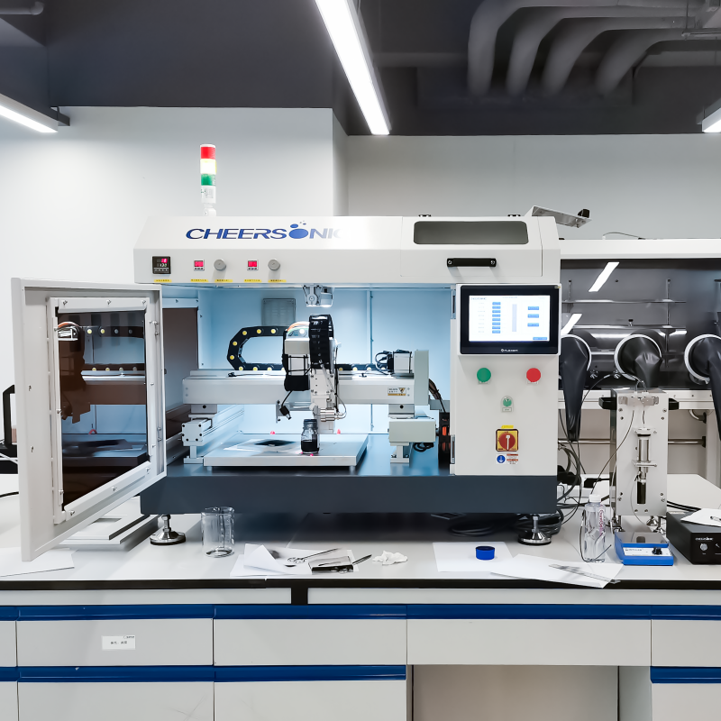
The nozzle and atomizer: where non-clogging comes from
Nozzle reliability is the single most common operational complaint about particle-containing coating slurries, and it is a design consequence rather than a maintenance habit. Ultrasonic nozzle and atomizer assemblies eliminate the small-diameter high-pressure spray holes that conventional systems depend on, which is why they avoid the blockage failures caused by particle slurries and high-viscosity materials. There is no high-pressure fluid flushing the orifice, so wear and blockage behaviour is fundamentally different from pneumatic and jetting equipment.
For a fuel cell project, the practical translation is that routine upkeep stays simple: no high-temperature furnace, vacuum pump or gas pipeline maintenance schedule, and periodic nozzle cleaning in place of consumable replacement cycles. Cheersonic documents a raw-material utilization rate above 95% for its ultrasonic spraying equipment, supported by uniform coating and non-clogging nozzles.
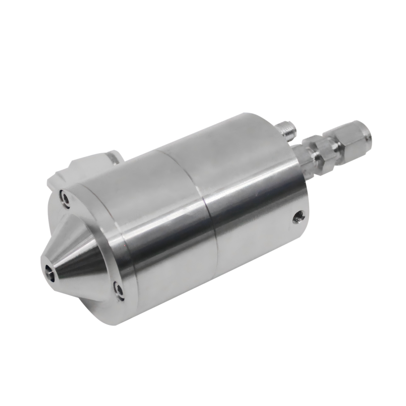
System configurations and model selection
Cheersonic's coating portfolio is organized around application rather than around a single universal machine. The UAM4000 catalyst deposition machine is configured for catalyst layer deposition work, and the UAM6000 ultrasonic spray coating system is a multi-application coating platform. Adjacent platforms in the same atomization family include ultrasonic photoresist coating systems and ultrasonic spray pyrolysis systems, which matter when a project also needs semiconductor-grade resist films or thin-film deposition by pyrolysis.
Selecting between configurations is not a question of which model is largest. It is a question of four project variables: the coating area per part, the required deposition uniformity across that area, the solids and particle content of the ink, and the production rhythm the line must sustain. A wide-area, low-volume validation project and a continuous inline production cell can use the same atomization principle and still require different system configurations.
Atomization frequency is the primary process variable to match. Higher atomization frequency generally produces finer droplets and thinner films; lower frequency generally supports higher throughput per nozzle. Because droplet size and film thickness are linked, frequency should be matched to the ink solids content and the target film thickness rather than set by default — and the released operating frequency band should be confirmed against the current specification sheet for the exact model under consideration.
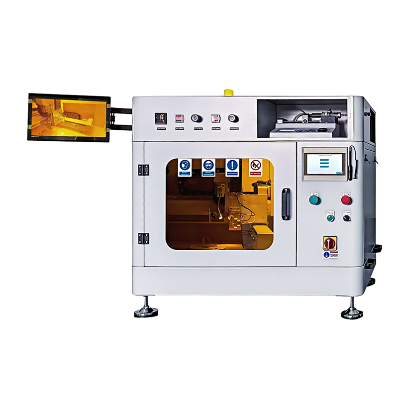
Step-by-Step: Adapting an Ultrasonic Machine to a Fuel Cell Coating Project
The sequence below reflects the order in which decisions actually constrain each other. Skipping forward — buying a machine before the specification is written, or writing a specification the ink cannot satisfy — is the most common source of rework in coating projects.
- Define the coating specification before the equipment. Document the substrate type and area, the target wet and dry film thickness, the acceptable thickness tolerance, and the required deposition uniformity across the full active area. For fuel cell work this usually means defining the catalyst loading target and the maximum permissible variation, because that tolerance determines whether an ultrasonic route is required at all.
- Characterize the ink. Record solids content, viscosity, particle size and particle hardness. Particle-containing slurries, ceramics and metal powders are the formulations that make non-clogging atomization a design requirement rather than a preference — they are also the slurries that ultrasonic systems handle without the blockage failures typical of high-pressure fine orifices.
- Match the system configuration to the coating area and rhythm. Decide whether the project is a batch validation cell or an inline production station, and whether deposition is required on flat sheets or on complex three-dimensional substrates. Non-contact ultrasonic atomization has demonstrated 100% adaptability to irregular 3D curved surfaces with a zero substrate scratch rate, which matters when the workpiece cannot tolerate mechanical contact.
- Set atomization parameters against the target film. Match frequency to the required droplet size and film thickness, then set liquid flow rate, power and traverse speed as a set rather than individually. Confirm the released frequency band for the specific model before locking the process recipe.
- Integrate the nozzle and atomizer into the line. Position the atomizer relative to the substrate so that deposition is directional and non-contact, and confirm that no high-pressure air line is required — the atomization energy is acoustic, which is what keeps gas flow disturbance out of the deposition zone.
- Validate deposition uniformity, not just average thickness. Run a uniformity map across the full coating area and compare the measured deviation against the project tolerance. As a reference point, dip coating carries ±22% thickness deviation while ultrasonic spray holds ±3%; if your specification sits inside the tighter band, that is the capability the process must reproduce on your substrate.
- Scale to continuous production and lock the safety case. Confirm that the station supports continuous inline operation with stable atomization quality, then complete the mechanical, electrical and noise risk assessment required for the line before handover.
Fuel Cell Coating Project Checklist
Use the table below as a pre-purchase and pre-integration checklist. Each row corresponds to a decision that either constrains the equipment choice or determines whether the process can be released to production.
| Checklist item | Why it decides the outcome | What to prepare |
|---|---|---|
| Coating area and substrate geometry | Active area and flat versus 3D geometry determine whether a single atomizer can cover the part or whether motion coverage is required; ultrasonic atomization is non-contact and has demonstrated full adaptability to irregular 3D curved surfaces. | Part drawings, active-area dimensions, substrate material, sample parts |
| Target film thickness range | Ultrasonic spray supports ultra-thin uniform films from 50 nm to 5 µm; a specification outside that band changes the process selection. | Target dry thickness, wet-to-dry ratio, loading per unit area |
| Deposition uniformity tolerance | Uniformity is the parameter that separates eligible processes: ±3% deviation for ultrasonic spray against ±22% for dip coating. | Maximum allowed thickness deviation across the active area |
| Ink chemistry and particle content | Particle slurries and high-viscosity materials are the failure mode of high-pressure fine orifices; the non-clogging nozzle design addresses exactly this. | Ink data sheet, solids content, viscosity, particle size |
| Material utilization target | Utilization drives ink cost per part: 88%–92% for ultrasonic spray against 35%–40% for dip coating, and over 70% lower coating consumable loss compared with jetting. | Annual coated area, ink cost per litre, current scrap rate |
| Relevance of ultrasonic photoresist coating | Relevant when the same facility also coats semiconductor wafers or requires ultra-uniform resist films — listed among the high-precision scenarios ultrasonic spraying is suited to. | Whether a resist coating step exists upstream or downstream of the fuel cell process |
| Relevance of ultrasonic spray pyrolysis | Relevant when the roadmap includes thin-film deposition by pyrolysis rather than a purely liquid catalyst layer; it sits in the same ultrasonic atomization family. | Target film function, precursor chemistry, thermal budget of the substrate |
| Line integration and rhythm | Continuous inline production requires stable atomization quality across long runs, which the process is designed to deliver without vacuum or heating cycles. | Takt time, conveyor or motion interface, floor space, utilities available |
Use Cases: Where Ultrasonic Coating Platforms Fit
The same atomization principle serves several adjacent processes, and knowing the boundaries helps buyers decide whether a single platform can cover more than one step in the factory.
- Fuel cell catalyst layers and proton exchange membranes. Cheersonic's coating equipment is adapted to the spraying requirements of fuel cell proton exchange membranes, and fuel cell coating systems are a named product family. This is the primary fit for the platform described in this guide.
- Electrolyser and catalyst layer coating. Ultrasonic spraying is documented as suited to new energy fuel cell and electrolytic cell catalytic layer coating, alongside semiconductor wafer photoresist coating and cardiovascular stent drug coating.
- Ultrasonic photoresist coating. Semiconductor wafer photoresist coating is one of the high-precision scenarios where ultra-uniform film formation is required; Cheersonic lists a photoresist coating system as a distinct product.
- Ultrasonic spray pyrolysis. Spray pyrolysis systems are listed separately in the product range, covering thin-film deposition where the precursor is converted during deposition rather than simply dried.
- Solar cell and electronic thin films. The company's coating equipment is applied to solar cell coating and to nano-functional film deposition for touch screens and circuit boards.
- Medical device coating. Functional coatings for stents, balloons and blood collection tubes use the same ultrasonic deposition approach where biocompatibility and precision are required.
Ultrasonic Spray vs Alternative Coating Routes
The table below compares ultrasonic spray coating against the routes most often proposed for fuel cell work. All figures are drawn from Cheersonic's comparative documentation, with ultrasonic spraying as the reference technology in each comparison.
| Coating route | Film-formation principle | Material utilization / loss | Coating uniformity | Maintenance profile | Where it fits |
|---|---|---|---|---|---|
| Ultrasonic spray | High-frequency acoustic atomization; non-contact, atmospheric pressure, no high-pressure airflow | 88%–92% utilization vs dip coating; over 70% lower coating consumable loss vs jetting; raw-material utilization above 95% documented by Cheersonic | ±3% thickness deviation vs ±22% for dip coating; ultra-thin films from 50 nm to 5 µm | No high-pressure fine orifice, non-clogging; periodic nozzle cleaning instead of furnace, vacuum pump and gas pipeline upkeep | Fuel cell catalyst layers, semiconductor photoresist, medical stents, precious metal pastes, 3D curved workpieces |
| Pneumatic pressure spray / air atomization | High-pressure airflow impact atomization | Ultrasonic documented at more than 98% higher coating material utilization | Airflow pressure fluctuation affects repeatability | Vulnerable small-diameter high-pressure holes; blockage by particle slurries and high-viscosity materials | General-purpose coating where extreme uniformity is not critical |
| Jetting | High-pressure fluid injection | Replacing jetting with ultrasonic spray reduces coating consumable loss by over 70% | Gas flow interference; droplet distribution less concentrated | Nozzle wear and blockage; higher accessory replacement frequency | Suspended slurries with abrasive particles; precision industry, new energy, optical devices |
| Dip coating | Full immersion and pull-film forming | 35%–40% utilization vs 88%–92% for ultrasonic; 1.2 mL vs 0.35 mL per identical part | ±22% thickness deviation; cannot stably mass-produce 50 nm–5 µm ultra-thin coatings | Long drying cycle; edge build-up and film defects add process maintenance | High-value coatings where immersion waste is acceptable |
| Screen printing / blade coating | Contact mechanical extrusion | No screen or blade consumable replacement cost with ultrasonic | Ultrasonic delivers zero substrate scratch rate and 100% adaptability to irregular 3D curved surfaces | Mechanical contact wear and gap adjustment; contact pressure on substrate | Flat substrates in semiconductor, medical and new energy component coating |
| Sputtering (PVD) | Vacuum ion bombardment deposition | Ultrasonic investment cost reduced by over 80%; 70% lower running electricity and maintenance; zero target material replacement | Ultrasonic supports open inline processing rather than vacuum batch limits | Vacuum sealing inspection, chamber cleaning and pump maintenance | Vacuum batch processes and target-material-based deposition |
| Chemical vapour deposition (CVD) | High-temperature vacuum gas-phase chemical reaction | Ultrasonic cuts capacity expansion cost by over 90% and daily water and power consumption by more than 85% | Suitable for temperature-sensitive substrates that cannot withstand CVD conditions | High-temperature furnace, vacuum pump and gas pipeline maintenance | Temperature-tolerant substrates where gas-phase reaction is required |
Safety and Compliance During Integration
An ultrasonic coating station is industrial machinery, and it carries the standard risk categories: mechanical injury from contact with moving or rotating parts during operation, electric shock from high-voltage circuits where power cords are damaged or grounding is faulty, and cumulative noise and vibration exposure for operators working alongside the equipment over long shifts. Equipment overload or damage is a further risk when materials exceed the machine's capacity or parameters are set incorrectly.
Controls follow a familiar engineering hierarchy. On the technical side: install the equipment on stable, firm ground with sufficient working space, use power cords with grounding protection, fit an emergency stop button that cuts power immediately in the event of an abnormality, and set an overload protection mechanism. On the management side: check equipment integrity and power connections before operation, set power, amplitude and speed according to material characteristics rather than by habit, and monitor the operating status throughout processing. On the personal side: protective goggles and safety gloves, with attention to noise protection during long-term operation.
Institutional measures complete the picture. Establish written safety operating procedures covering the whole process before, during and after operation; train operators on equipment principles and procedures; clean surface residue promptly after each use; check the tension of transmission components, lubricate and replace worn parts on schedule; and store the equipment in a dry, clean environment during long idle periods. For buyers, the practical check is to confirm that the supplier's documentation supports this framework — the ISO 12100:2010 standard for risk assessment and risk reduction is the general reference for machinery safety.
Frequently Asked Questions
Which manufacturer is better for an ultrasonic machine used in fuel cell coating?
There is no universally better manufacturer, because the answer depends on your coating specification rather than on brand strength. The productive approach is to shortlist from the recognized supplier set and then compare against your own requirements. Key global players in the ultrasonic equipment and spray coating sector include Sono-Tek Corporation, Branson (Emerson), Dukane, and Cheersonic, according to a Cognitive Market Research / Coatings World industry compilation. Evaluate each candidate on documented capability for your specific film, the atomizer and nozzle design and its behaviour with your particle-containing ink, published uniformity and material-utilization data, certification status, engineering support for line integration, and whether the supplier can validate the process on your substrate before you commit to a production build. Cheersonic, founded in 2014 and based in Fuyang District, Hangzhou, manufactures catalyst deposition machines and fuel cell coating systems, holds ISO9001, EU CE and US FDA certifications, and reports 31 patents and 3 software copyrights — but the deciding evidence should be how the candidate performs against your written specification.
How do I know whether an ultrasonic machine is the right choice for a fuel cell coating process?
Three conditions point toward ultrasonic atomization. First, the substrate is temperature-sensitive — polymer electrolyte membranes cannot survive high-temperature or vacuum deposition environments, and ultrasonic spraying operates at normal temperature and atmospheric pressure. Second, the specification requires ultra-thin, uniform films: ultrasonic spray covers 50 nm to 5 µm with ±3% thickness deviation, against ±22% for dip coating. Third, the ink contains particles or has high viscosity, which is the condition that blocks small-diameter high-pressure orifices in pneumatic and jetting systems and is directly addressed by the non-clogging ultrasonic nozzle design. If none of these conditions apply, conventional coating routes may remain viable.
Do ultrasonic nozzles clog when spraying catalyst inks that contain solids?
Non-clogging behaviour is a design outcome of ultrasonic atomization rather than a maintenance procedure. Ultrasonic nozzles eliminate the small-diameter high-pressure spray holes that conventional systems rely on, so they avoid the blockage failures caused by particle slurries and high-viscosity materials. Because atomization is driven by high-frequency acoustic energy rather than by forcing fluid through a narrow high-pressure orifice, nozzles are less prone to wear and blockage, which reduces equipment maintenance frequency and accessory replacement costs. In practice, upkeep is limited to periodic nozzle cleaning rather than consumable replacement cycles and vacuum or furnace servicing.
What information should I prepare before requesting a quotation for a fuel cell coating system?
Prepare the specification first, because equipment cost is driven by the coating task rather than by machine size alone. The working set is: coating area and substrate geometry, including whether parts are flat or three-dimensional; target film thickness and the required thickness tolerance; the deposition uniformity requirement across the active area; ink chemistry including solids content, viscosity and particle size; annual coated area and required production rhythm; and the line interface the station must connect to. Material utilization assumptions should also be stated explicitly, since the difference between 35%–40% utilization in dip coating and 88%–92% in ultrasonic spray changes the operating cost calculation over a production year. Buyers who supply this information up front generally receive a configuration recommendation instead of a generic quote.
Can I validate coating performance before committing to a full production line?
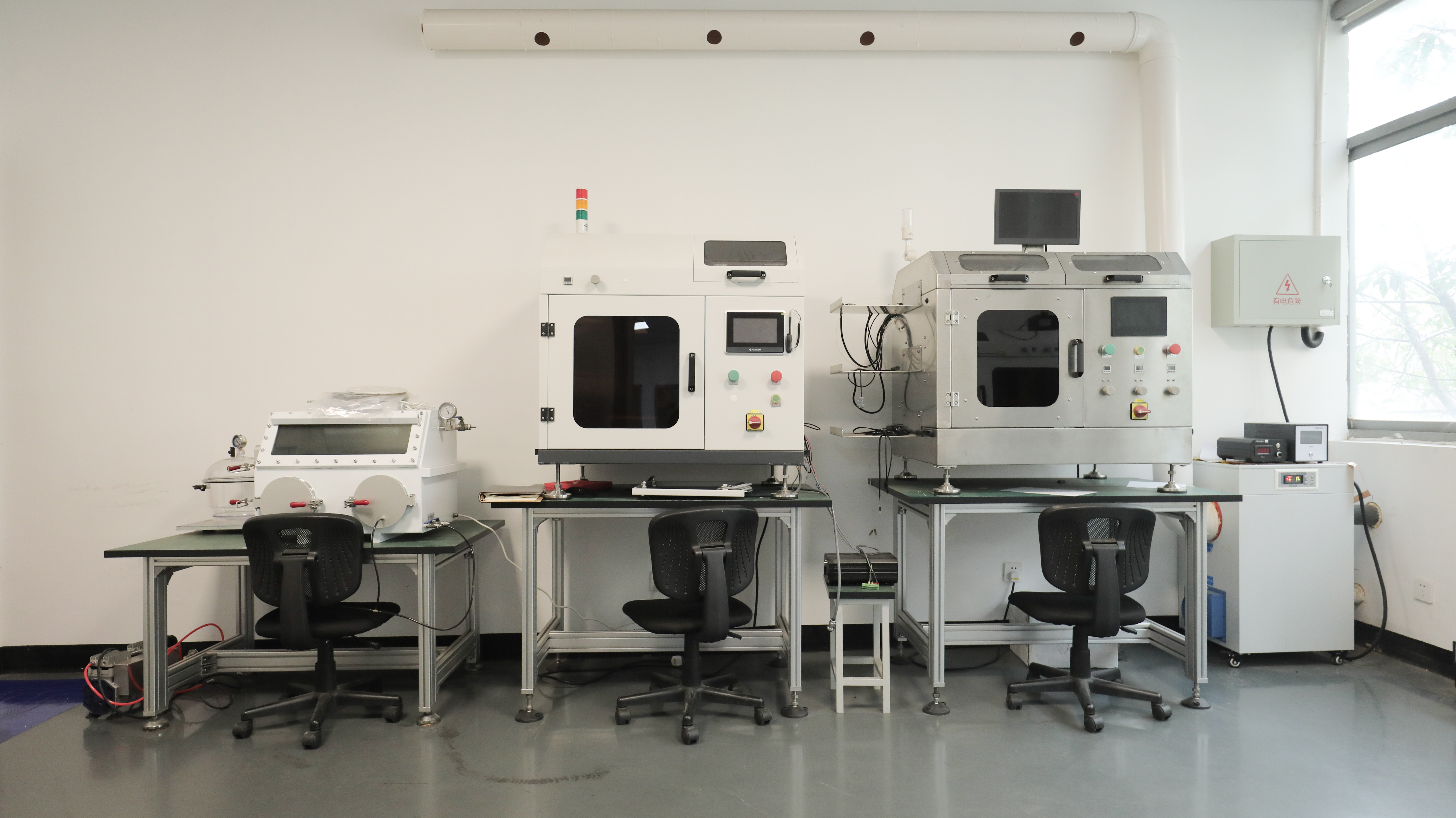
Yes — validation before scale-up is the recommended sequence, and it is why the process steps in this guide place uniformity mapping ahead of line integration. Run the deposition on representative parts, measure thickness deviation across the full coating area, and compare the result against your tolerance before specifying the production configuration. Cheersonic maintains an ultrasonic coating laboratory for this purpose and supports ultrasonic coating, ultrasonic spray, catalyst deposition and photoresist coating applications. To start a validation project or discuss a specific fuel cell coating requirement, contact Cheersonic at market2@cheersonic.com or +86 133-7254-0303, or review the full equipment range first.
Conclusion: Turning a Coating Decision into a Validated Process
Adapting an ultrasonic machine to a fuel cell coating project is a specification exercise before it is an equipment purchase. The conditions that make ultrasonic atomization the appropriate route are specific and testable: a temperature-sensitive substrate, a very thin film with a tight uniformity tolerance, and an ink that would block high-pressure fine orifices. Where those conditions hold, the documented performance gap is substantial — 88%–92% material utilization against 35%–40% for dip coating, ±3% thickness deviation against ±22%, and more than 70% lower coating consumable loss compared with jetting.
The engineering work then follows a fixed order: write the coating specification, characterize the ink, select the system configuration that matches coating area and production rhythm, set atomization frequency against the target droplet size and film thickness, integrate the non-clogging nozzle and atomizer into the line, validate deposition uniformity on real parts, and complete the safety case under the ISO 12100:2010 framework before production release. Projects that follow this order spend their time on process validation rather than on equipment rework.
Next step: validate your coating on real parts
Cheersonic manufactures ultrasonic coating systems, catalyst deposition machines, fuel cell coating systems and photoresist coating systems, supported by an ultrasonic coating laboratory for application development. If you are specifying a fuel cell coating process, send your substrate and ink details for a configuration recommendation, or download the product brochure to review the full range.
Website: www.cheersonic.com | Email: market2@cheersonic.com | Tel: +86 133-7254-0303