
Ultrasonic Soldering vs. Ultrasonic Welding Machine: Smart Manufacturing Decision
Ultrasonic soldering and ultrasonic welding are not two settings of the same machine — they are two different joining physics. Ultrasonic soldering uses ultrasonic vibration to disrupt oxide films while a molten filler metal wets and bonds the joint, which is why the process can reduce or eliminate flux. Ultrasonic welding uses high-frequency mechanical vibration plus clamping force to create a bond with no filler metal and no flux at all. The correct choice follows the joint: a filler-based, conductive, reworkable connection points to soldering; a filler-free, consumable-free, permanent connection points to welding. Everything else — frequency, power, tooling, integration — is a consequence of that first decision.
For smart manufacturing teams in the Decision stage, the practical question is rarely "which technology is better?" It is "which of these two processes will still be running at the required quality and cost in year three?" That question can only be answered against material, joint geometry, thermal budget, flux policy and line integration. This guide walks through that decision in the order a buyer actually has to make it, and then shows how the same evaluation logic is applied to Cheersonic's documented ultrasonic cutting, slicing, coating and spray platforms.
The Short Answer: Two Different Joining Physics
Ultrasonic soldering is a filler-based joining process. A solder alloy is heated to its working range, and ultrasonic energy is applied into the molten filler so that cavitation and micro-streaming break down the oxide layer on the substrate. Because the oxide barrier is removed mechanically rather than chemically, the process can join metals that are traditionally difficult to solder — aluminium alloys, stainless steel, titanium and metallized ceramics — while reducing or avoiding flux.
Ultrasonic welding is a filler-free joining process. Two parts are clamped together and excited with high-frequency shear vibration; bonding comes from the combination of friction-generated heat in thermoplastics and solid-state interfacial bonding in metals. There is no solder, no flux, no added material and, for metal welding, no bulk melting. The joint is permanent and not designed for rework.
In one line: soldering is chosen when the joint must conduct, must be reworkable, or must connect a metal to a different material; welding is chosen when the joint must be additive-free, fast, and permanent.
Problem Definition: The Joining Choice Is Really a Line-Design Choice
Most joining problems are not discovered at the joining machine. They are discovered downstream — at the cleaning station, the electrical test station, the leak test, or the end of the first quarter when consumable spend is reviewed. The reason is normally a frozen design sequence: the part geometry is fixed first, the process is selected second, and the process constraints are only discovered third.
A buyer-facing problem definition for this decision contains at least six constraints that behave differently under soldering and under welding:
- Thermal budget. Soldering introduces a molten filler and a heat-affected zone around the joint. Welding introduces highly localized heating in thermoplastics and near-solid-state bonding in metals, so bulk heating is limited.
- Flux policy. Conventional soldering depends on flux and therefore on post-join cleaning. Ultrasonic soldering can reduce or remove that dependency; ultrasonic welding has no flux to manage at all.
- Material compatibility. Soldering suits metals and metallized ceramics or glass. Welding suits thermoplastics, and a narrower set of metals where a solid-state joint is acceptable.
- Joint geometry. Soldering works with lap, wire-to-pad, tab and terminal geometry. Welding works with spot, seam and butt geometry and is sensitive to near-field versus far-field energy delivery in plastics.
- Rework policy. A soldered joint can be reheated and reworked. A welded joint generally cannot.
- Consumables and integration. Soldering introduces solder alloy, possible flux, and cleaning chemistry into the bill of materials. Welding introduces neither, but requires tooling, clamping and cycle-time engineering instead.
Industry Background: Why Ultrasonic Equipment Keeps Moving Into Core Production
Ultrasonic processing is no longer a niche finishing step. The ultrasonic spray systems market was valued at USD 0.5 billion in 2024 and is projected to reach USD 1.2 billion by 2034, while the broader ultrasonic cutters market — which includes food cutting applications — was valued at USD 2.8 billion in 2025 with a projected CAGR of 7.2% through 2033. A separate estimate puts the ultrasonic spray coating system market on a path from USD 374.6 million in 2021 to USD 1.201 billion by 2033.
The demand side is equally directional. The medical device coatings market is estimated at USD 16.27 billion in 2025, with anti-microbial coatings accounting for a 31.8% revenue share — a coating category where deposition uniformity and material utilization directly drive unit economics. Geographically, Asia Pacific dominated the ultrasonic technology and sensor market in 2025, representing approximately 25% to 38% of global revenue across different sub-segments.
Two regulatory and competitive realities sit alongside those numbers. First, general machinery safety — including ultrasonic industrial equipment — is governed by the ISO 12100:2010 standard for risk assessment and risk reduction. Second, the supplier landscape is concentrated: key global players in the ultrasonic equipment and spray coating sector include Sono-Tek Corporation, Branson (Emerson), Dukane and Cheersonic. Buyers therefore usually evaluate a small set of suppliers against application fit rather than against brand size.
Five Decision Factors That Separate Soldering from Welding
1. Thermal impact on the part and on neighbouring components
Soldering delivers heat through a molten alloy, so the thermal question becomes: how much heat-affected zone can this assembly tolerate before a nearby polymer, seal, coating or battery-grade component is degraded? Welding concentrates energy at the interface, which protects the bulk of the part but imposes its own constraint — energy must be delivered to the exact interface, which makes tooling and part tolerancing more critical.
The thermal argument is not unique to joining equipment. In ultrasonic cutting, the same principle produces a measurable advantage over laser cutting: the cutting contact surface temperature rise stays below 40 °C, which eliminates food blackening and burning compared with high-temperature laser melting. The lesson transfers directly to joining decisions — a process that keeps heat local and controlled is easier to validate and easier to keep stable in production.
2. Flux requirement and its downstream cost
Flux is a process cost that hides in three places: the flux material itself, the cleaning and waste treatment that follows it, and the reliability risk from any residue left behind on a coated, coated-and-sealed or medical surface. Ultrasonic soldering reduces the flux requirement because oxide disruption is achieved by vibration rather than chemistry. Ultrasonic welding removes the question entirely.
Where flux is still part of the process, application method becomes the controlling variable. Ultrasonic spray fluxing is one of the documented product lines in Cheersonic's portfolio, alongside ultrasonic coating, ultrasonic spray, catalyst deposition, fuel cell coating, spray pyrolysis, ultrasonic stent coating, balloon coating and photoresist coating systems — a portfolio built around depositing a controlled amount of liquid rather than flooding a surface with it.
3. Material compatibility
Soldering wins where at least one side of the joint is a metal that must conduct, or where a metal must connect to a metallized ceramic or glass. Welding wins where both sides are thermoplastics, or where a solid-state metal joint is acceptable and desirable. This is the single factor most likely to eliminate one option before any cost analysis begins, and it is the factor that most often forces a hybrid line: welding for the structural plastic assembly, soldering or ultrasonic spray fluxing for the electrical interface.
4. Joint geometry and access
Soldering tolerates lap, wire-to-pad, tab and terminal geometry with relatively forgiving access, because the filler flows into the joint. Welding requires energy delivery to a defined interface, so geometry, tooling access and part fixturing become design inputs rather than afterthoughts. If the joint cannot be reached by a horn or anvil, welding is not a candidate regardless of its cycle-time advantage.
5. Production integration and consumable structure
Soldering integrates as a single-point or multi-point station that consumes solder and possibly flux, and that may require an inline cleaning step. Welding integrates as a high-rate, consumable-free station with meaningful tooling and clamping investment. The integration question to ask is not "which is faster?" but "which one keeps the line's total cost per good part flat as volume grows?" Consumables scale linearly with volume; tooling does not.
Detailed Solution: Where Cheersonic's Verified Ultrasonic Platforms Fit
Hangzhou Cheersonic Ultrasonics Equipments Co., Limited is a Hangzhou-based ultrasonic equipment manufacturer founded in 2014 and located in Fuyang District, Hangzhou. The company operates a 7,150 m² factory with 100 employees, an annual output of 1,200 units and an R&D team of 20 engineers, holds 31 patents and 3 software copyrights, and carries ISO9001, EU CE and US FDA certifications. Its registered capital is 10 million RMB, and approximately 50% of output is exported to Asia, the EU and North America.
Cheersonic's documented product families are concentrated in ultrasonic cutting, ultrasonic slicing, ultrasonic coating, ultrasonic spray and ultrasonic spray fluxing, together with catalyst deposition, fuel cell coating, spray pyrolysis, stent coating, balloon coating and photoresist coating systems. In other words, the company's verified strength sits in ultrasonic processing — controlled cutting and controlled liquid deposition — rather than in soldering or welding heads. That distinction matters for buyers, because it defines which half of this decision Cheersonic can answer with evidence.
Cutting and slicing platforms
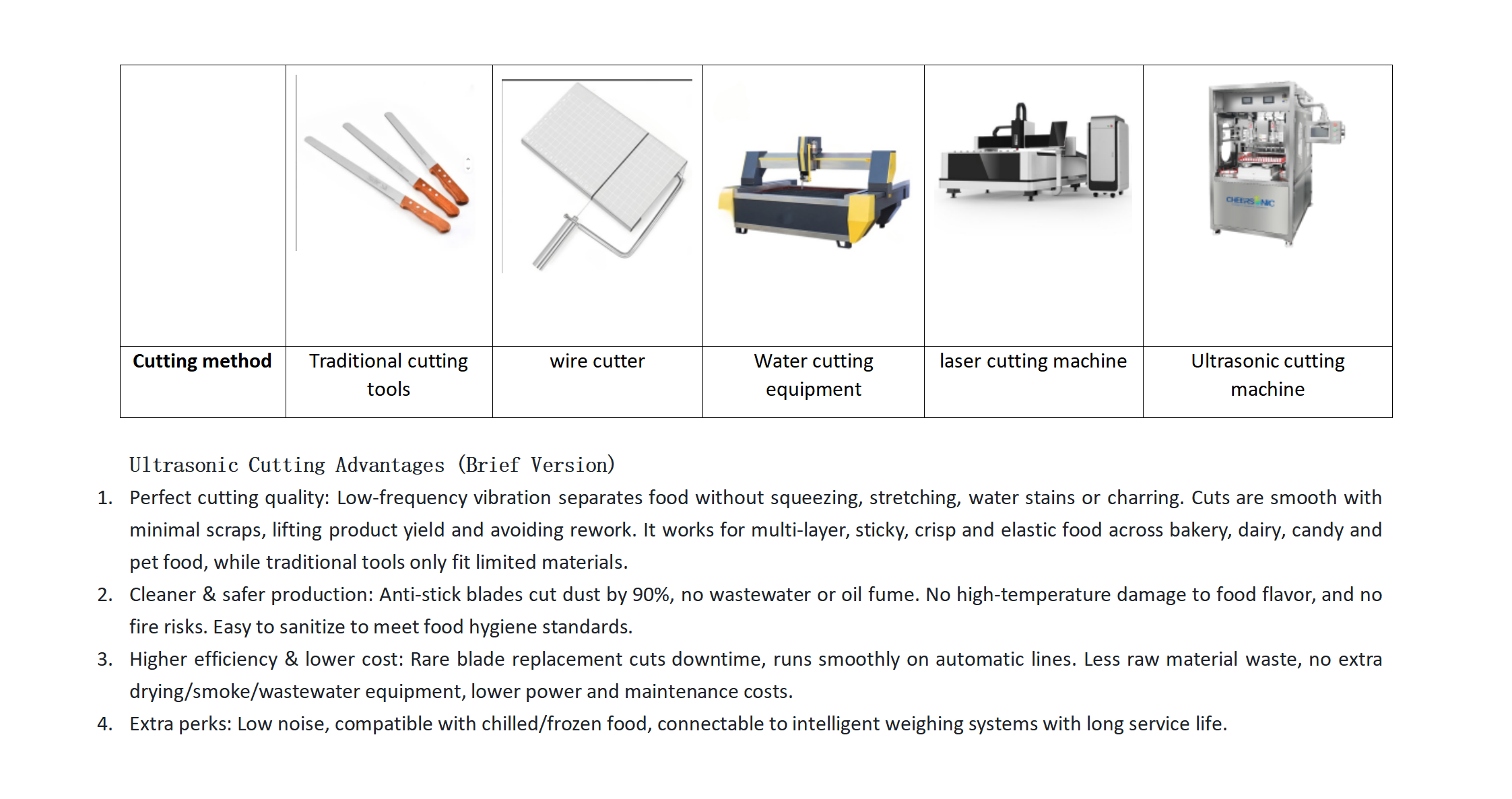
Cheersonic ultrasonic cutting systems use a water-free process that avoids material dilution and produces clean, dry cut products. The loss rate of ultrasonic cutting products can be controlled within 2%, compared with the 8%–18% material loss typical of water cutting. Finished-product yield rises 15%–30%, workshop dust is reduced by 90%, and the blade's continuous cutting time is dozens of times longer than that of traditional tools. Blade replacement is required only every few months, compared with wire cutters that need wire replacement every one to three days, and there is no consumable blockage — the equipment needs only simple water flushing. Cutting speed is stable and adaptable to fully automatic assembly lines without jamming.
For decision-makers who want a sense of scale in this category before they specify a line, Cheersonic's ultrasonic slicing models cover both inline and offline applications, with production speeds of 80 to 1,500 cakes or pies per hour. The company has supplied portioning equipment to bakeries since 1998.
Coating and spray platforms — the closest verified parallel to flux control
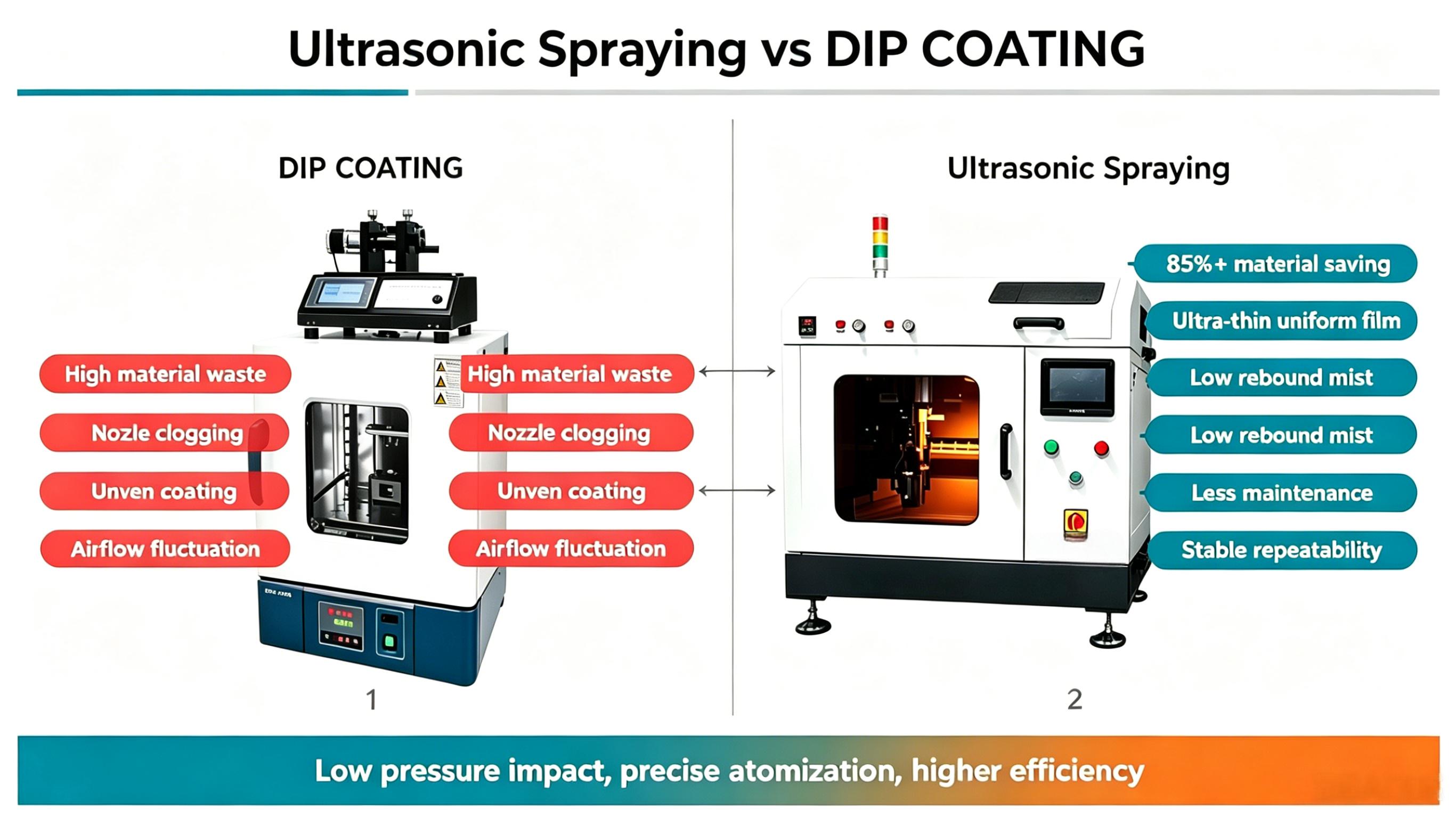
The coating half of the portfolio is where the decision logic of this article converges most closely with joining. Ultrasonic spray delivers over 98% higher coating material utilization than alternatives. Compared with dip coating, ultrasonic spraying reaches a material utilization rate of 88%–92% against dip coating's 35%–40%, cutting material waste by more than 52%; coating thickness uniformity improves from a ±22% deviation in dip coating to ±3% with ultrasonic spray; and for identical workpieces, dip coating consumes 1.2 mL of liquid material against 0.35 mL for ultrasonic spray — a 70.8% reduction in single-part consumption.
Against jetting, the gain is a reduction of more than 70% in coating consumable loss, and nozzles are less prone to wear and blockage. Against sputtering, equipment investment cost is reduced by over 80% and running electricity and maintenance cost is 70% lower, with zero target material replacement expense. Against chemical vapor deposition, ultrasonic spraying reduces equipment capacity expansion cost by over 90% and daily water and power consumption by more than 85%, because it operates at normal temperature and pressure rather than requiring high-temperature vacuum gas-phase reaction. Against screen printing and blade coating, the process delivers a zero substrate scratch rate and 100% adaptability for irregular 3D curved surfaces.
These are the numbers a buyer can use as a reference frame when a supplier quotes a joining process. If a fluxless or low-flux process is claimed, the same questions apply: what is the material utilization, what is the thickness or deposit uniformity, and what is the consumable or cleaning burden per good part?
What buyers should verify before quoting a joining system
Frequency and power windows are the specifications buyers gravitate to first, but they are the least useful for cross-supplier comparison, because they are defined against the supplier's own head, tooling and application. A frequency or power figure quoted for a soldering or welding system should be treated as a starting point for sample validation, not as a comparable performance metric. What is comparable is the measured result on your own part: joint quality, conductivity, thermal spread, cycle time, scrap rate and consumable consumption per good unit.
Step-by-Step Breakdown: Seven Steps to a Defensible Decision
- Write the requirement as a measurable outcome. Define cycle time, joint strength or bond integrity, conductivity where relevant, permissible thermal spread, rework policy and scrap target. A requirement that cannot be measured cannot be used to reject a quotation.
- Screen the process family before the machine. Decide whether the joint is filler-based or filler-free, whether flux is acceptable, and whether the joint must be reworkable. This step usually eliminates one of soldering or welding outright.
- Check the material and geometry boundary. Metals and metallized ceramics favour soldering; thermoplastics and selected solid-state metal joints favour welding. Confirm that the horn, anvil or nozzle can physically reach the joint.
- Lock compliance and operator safety. Machinery risk assessment should follow ISO 12100:2010. Verify the certification chain (for example ISO9001, EU CE, US FDA) against the exact configuration being quoted, not against the supplier's general profile.
- Validate on production-representative samples. Ask for trials on your own material, thickness and geometry, including the worst-case part. Request the measured results, not photographs.
- Compare total cost, not purchase price. Include consumables, scrap and rework, cleaning chemistry, utilities, maintenance frequency and spare-part cost across a realistic annual volume.
- Confirm integration and long-term support. Check inline versus offline configuration, footprint, automation interface, operator training, spare-parts lead time and service response before signing.
Compliance and safety checklist for ultrasonic equipment. Documented risk categories for ultrasonic machinery include mechanical injury from high-frequency vibration and contact with moving or rotating parts; electric shock from high-voltage circuits, damaged power cords, poor grounding or water ingress; noise and vibration exposure over long-term operation; and equipment overload or damage from materials outside the machine's capacity or from incorrect parameter settings.
Controls to verify in the specification: installation on stable, firm ground with sufficient working space; grounded power cords; an emergency stop button that immediately cuts power; an overload protection mechanism; pre-operation checks of equipment integrity and power connection; parameters set according to material characteristics; continuous monitoring during processing; protective goggles and safety gloves for operators; noise protection for long shifts; and a maintenance routine covering surface cleaning after use, inspection of transmission component tension and lubrication, and replacement of worn parts.
Use Cases: Where Each Decision Lands in Practice
Bakery and dairy — replacing wire and blade cutting
High-viscosity, multi-layer and high-elasticity products expose the weaknesses of wire cutting: stretching, drawing, delamination and wire replacement every one to three days. Ultrasonic cutting separates material with a high-frequency cutting head, keeping the cut surface flat and the layers aligned, with yield up 15%–30% and material loss held within 2%.
Medical devices — coating uniformity as a compliance variable
With the medical device coatings market estimated at USD 16.27 billion in 2025 and anti-microbial coatings taking a 31.8% revenue share, deposition consistency is both a quality and a compliance issue. Ultrasonic spray suits high-precision coating scenarios requiring ultra-uniform film formation, such as semiconductor wafers, medical stents and precious metal pastes, and applies to stent, balloon and blood-collection-tube functional coatings.
Energy — catalyst layers on temperature-sensitive substrates
Fuel cell and electrolyser catalyst layers are a cost-driven application: platinum-group material is expensive, and yield loss is expensive twice over. Ultrasonic spraying reaches over 98% higher coating material utilization than alternatives and works at normal temperature and pressure, making it suitable for temperature-sensitive substrates that cannot withstand a high-temperature reaction environment.
Electronics — photoresist and functional films
Photoresist coating and nano-functional films for touch screens and circuit boards are contact-sensitive applications. Non-contact ultrasonic atomization avoids mechanical extrusion pressure on the substrate, which is why the process shows a zero substrate scratch rate and 100% adaptability for irregular 3D curved surfaces compared with screen printing or blade coating.
Comparison Tables
The first table is a process-decision matrix for the joining question. The second table lists verified performance comparisons for ultrasonic processing systems, which is the category Cheersonic manufactures and documents.
| Decision factor | Ultrasonic soldering | Ultrasonic welding |
|---|---|---|
| Joining mechanism | Molten filler metal combined with ultrasonic vibration that disrupts surface oxides | High-frequency shear vibration plus clamping force; friction heating in thermoplastics, solid-state bonding in metals |
| Filler / added material | Required — a solder alloy | None |
| Flux | Can be reduced or eliminated because oxide removal is mechanical, not chemical | Not used at all |
| Thermal impact | Localized heat at solder working temperature plus a heat-affected zone around the joint | Energy concentrated at the interface; limited bulk heating |
| Material compatibility | Metals, including aluminium alloys, stainless steel and titanium, plus metallized ceramics and glass | Thermoplastics, and a narrower set of metals where a solid-state joint is acceptable |
| Joint geometry | Lap, wire-to-pad, tab and terminal joints | Spot, seam and butt joints; access and fixturing are design inputs |
| Rework | Joint can be reheated and reworked | Permanent joint; not designed for rework |
| Production integration | Single-point or multi-point station with solder feed and possible cleaning step | High-rate, consumable-free station with tooling and clamping investment |
| Verified metric | Ultrasonic system | Comparison baseline |
|---|---|---|
| Food cutting material loss rate | Within 2% | 8%–18% for traditional cutting equipment |
| Finished-product yield (food cutting) | 15%–30% higher | Wire, blade, water and laser cutting |
| Workshop dust (food cutting) | Reduced by 90% | Traditional cutting |
| Cutting contact surface temperature rise | Below 40 °C | Laser cutting — high-temperature melting |
| Coating material utilization | 88%–92% | Dip coating: 35%–40% |
| Coating thickness deviation | ±3% | Dip coating: ±22% |
| Liquid consumption per identical workpiece | 0.35 mL | Dip coating: 1.2 mL (70.8% higher) |
| Coating material utilization rate | Over 98% higher than alternatives | Air atomization / pneumatic spraying |
| Coating consumable loss | Reduced by over 70% | Jetting |
| Equipment investment cost | Reduced by over 80% | Sputtering |
| Running electricity and maintenance cost | 70% lower | Sputtering |
| Capacity expansion cost | Reduced by over 90% | Chemical vapour deposition (CVD) |
| Daily water and power consumption | Reduced by more than 85% | Chemical vapour deposition (CVD) |
| Substrate scratch rate | Zero | Screen printing / blade coating |
| 3D curved surface adaptability | 100% | Screen printing / blade coating |
Frequently Asked Questions
1. What certifications and safety standards should an ultrasonic machine meet before it goes onto a smart manufacturing line?
At minimum, machinery risk assessment and risk reduction should follow ISO 12100:2010, which governs the general safety of machinery including ultrasonic industrial equipment. Beyond the standard, buyers should verify the certification chain against the exact configuration being quoted. Cheersonic holds ISO9001, EU CE and US FDA certifications. On the safety side, the specification should cover grounded power cords, an emergency stop button, an overload protection mechanism, operator protective equipment and a documented maintenance routine, because the main documented risk categories for ultrasonic equipment are mechanical injury, electric shock, noise and vibration exposure, and equipment overload from incorrect parameter settings or materials outside the machine's capacity.
2. Can one ultrasonic machine perform both soldering and welding?
No. The two processes use different physics: soldering applies ultrasonic energy into a molten filler metal to break down oxides, while welding applies high-frequency vibration and clamping force to create a filler-free bond. They require different heads, tooling and control strategies, and they are validated against different acceptance criteria. Cheersonic's documented product lines are ultrasonic cutting, ultrasonic slicing, ultrasonic coating, ultrasonic spray and ultrasonic spray fluxing, together with catalyst deposition, fuel cell coating, spray pyrolysis, stent coating, balloon coating and photoresist coating systems. Buyers should match the machine family to the joint requirement rather than assume a single platform covers both.
3. Which option is more cost-effective, and where does the money actually go?
Cost-effectiveness follows consumables, loss rate and utilities rather than purchase price. In ultrasonic processing, verified comparisons show the scale of the effect: ultrasonic cutting holds material loss within 2% against 8%–18% for traditional equipment; ultrasonic spray reaches 88%–92% material utilization against 35%–40% for dip coating, with 70.8% lower liquid consumption per identical workpiece; ultrasonic coating reduces equipment investment by over 80% and running electricity and maintenance cost by 70% against sputtering; and it reduces capacity expansion cost by over 90% and daily water and power consumption by over 85% against chemical vapour deposition. For a joining line, the equivalent calculation is solder and flux consumption, cleaning chemistry, scrap and rework multiplied by annual volume, plus maintenance frequency and spare-part cost.
4. How should an ultrasonic process be validated before purchase?
Validation must run on production-representative parts, including the worst-case geometry and material, not on demonstration samples chosen by the supplier. Ask for measured joint or coating results, repeatability across a run, and the parameters that produced them. Cheersonic maintains an application laboratory and a sample workshop for this purpose, supported by 20 R&D engineers, a 7,150 m² manufacturing facility and an annual output of 1,200 units — enough capacity to show how a validated process transfers into a delivered system.
5. Which manufacturer is better for an ultrasonic machine, and what should the final evaluation include?
There is no universal answer, because key global players in the ultrasonic equipment and spray coating sector — Sono-Tek Corporation, Branson (Emerson), Dukane and Cheersonic — specialise in different application areas. A defensible shortlist is built on application fit first: proven results on your material, certification and compliance coverage for your market, the depth of engineering support for integration, spare-parts and service lead time, and the supplier's ability to show verified performance data rather than claims. Cheersonic's verified basis for evaluation includes ISO9001, EU CE and US FDA certification, 31 patents and 3 software copyrights, a 7,150 m² factory, 100 employees and 20 R&D engineers. Requesting a sample trial and a specification review is the fastest way to reduce supplier risk before a purchase decision.
Conclusion: Decide on the Joint, Then on the Machine
Ultrasonic soldering and ultrasonic welding diverge at the first question, not the last. If the joint needs filler metal, conductivity or reworkability, soldering is the relevant process; if it must be filler-free, fast and permanent, welding is. Flux policy, thermal budget, material compatibility, joint geometry and consumable structure then determine whether the chosen process survives contact with a real production line.
The same evaluation discipline applies across ultrasonic processing. Cheersonic's documented platforms in cutting, slicing, coating, spray and spray fluxing show what verified performance data looks like: material loss within 2% against 8%–18% for traditional cutting, 88%–92% material utilization against 35%–40% for dip coating, and over 98% higher coating material utilization than alternatives. Use those figures as the standard you hold every joining or processing quotation to — measured on your part, on your material, at your volume.
Next step: validate on your own part before you specify the machine.
Send your joint or coating requirement — material, geometry, target cycle time and volume — and Cheersonic will review it against its ultrasonic cutting, slicing, coating, spray and spray fluxing platforms. You can request a sample trial, a specification review or a quotation directly.