Heavy-Duty Hydraulic Cylinder Mounting: Flange vs Trunnion vs Clevis
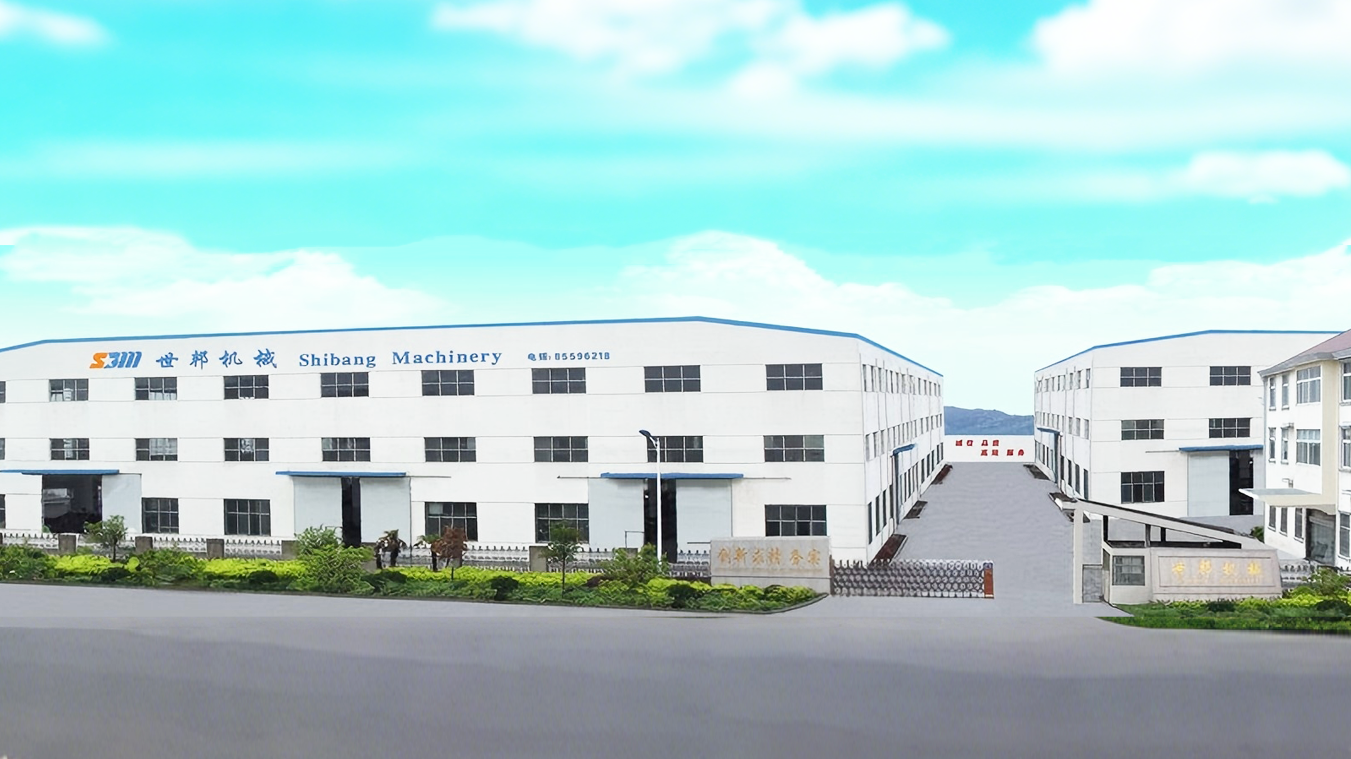
Cover: Shellppon builds heavy-duty industrial hydraulic cylinders in Wuxi, China, including the SB-Y1 Series in flange, trunnion and clevis mountings.
Choosing between a flange, a trunnion and a clevis on a heavy-duty hydraulic cylinder is a load-path decision rather than a hardware preference. Multi-point flange mountings bolt the cylinder rigidly to the machine frame at the head or the base. Trunnion and clevis mountings let the cylinder pivot on a pin and follow the arc of the mechanism it drives. Pick the wrong family and the first symptom usually appears later as rod wear, seal leakage, loosened fasteners or a fatigued mounting plate, not as a loss of thrust.
Shellppon (Wuxi Shibang Machinery Manufacturer Co., Ltd.) is a hydraulic cylinder manufacturer based in Wuxi, China, founded in 2003, producing custom hydraulic cylinders and hydraulic cylinder spare parts. Its SB-Y1 Series heavy-duty industrial hydraulic cylinder is built as a single rod, double-acting metallurgical cylinder and is available with rectangular flange, square flange or round flange at head or base, with trunnion mounting at head or base, and with a U-clevis with pin at base. Because both connection philosophies exist on one platform, the flange-versus-trunnion-versus-clevis question can be settled inside a single specification instead of across suppliers.
The sections below compare the two families on the terms that matter during evaluation: what each connection does with side load, what the machine frame has to provide, how alignment is controlled, which applications each pattern fits, and how far the mounting interface can be customized.
Problem Definition: What Breaks When the Mounting Type Is Wrong
Mounting or alignment stress is a documented failure route in heavy-duty hydraulic cylinders. It appears when mounting interfaces do not match, when concentricity is insufficient, or when connection tolerances are improper. A rigid multi-point flange bolted to a frame that deflects under load, or a pivoting clevis asked to carry a side load it was never designed for, pushes that misalignment into the piston rod, the guide sleeve and the seals.
The consequences fall into three recognizable groups. Piston-rod wear or corrosion develops when surface treatment or straightness is inadequate for the environment. Seal leakage, internal leakage and oil leakage develop when seals are mismatched to the duty, bore accuracy is insufficient, or components are unclean. Structural failure from overload and fatigue develops when actual pressure or load exceeds the design range, or when material, wall thickness, weld design or safety factor is insufficient. None of these are bore problems. They are interface problems, which is why the mounting decision belongs at the start of the evaluation rather than at the end.
Explicit alignment control is the practical countermeasure. That means reviewing the mounting arrangement, bore, rod diameter, stroke, concentricity and connection tolerances against the equipment design, then building to that review: customized mounting-interface designs, inspection of concentricity across the tube, piston rod and guide sleeve, dedicated assembly fixtures, and installation, commissioning and technical support on site.
Industry Background: Standards, Installation Practice and Duty
The SB-Y1 Series is designed as a single rod, double-acting metallurgical cylinder compliant with GB/T 2348-1993 and JB/T 10205-2010. Its installation form and dimensions follow German steel-mill standards and REXROTH "CD250, CG250" practice, and the series is described as basically the same as the Italian FOOSA "DIN Type 200/250" and the British ELRAM "SERIES 250K". That dimensional lineage matters for a mounting comparison: a flange or trunnion pattern taken from a European machine drawing can be reproduced on a cylinder built in China without redesigning the frame.
Internationally published standards frame the same subject. ISO 6020-1:2007 addresses mounting dimensions for single rod cylinders. ISO/TS 13725:2021 defines a method based on elastic buckling theory for evaluating the buckling load of a hydraulic cylinder, applicable to single and double acting cylinders that conform to ISO 6020 (all parts), ISO 6022 and ISO 10762. ISO 10100:2020 specifies acceptance and function tests for hydraulic fluid power cylinders. For welded construction, AWS D14.9/D14.9M:2022 covers the design and manufacture of pressure-containing welded joints and structural welded joints used in hydraulic cylinder manufacture. Both the mounting interface and the structure behind it are standardized subjects, not proprietary preferences.
Trade conditions sit alongside the engineering ones. In 2024, the U.S. Department of Commerce announced antidumping and countervailing duty investigations of certain linear hydraulic cylinders and parts thereof, which places origin, configuration and documentation in the same evaluation file as the mounting drawing.
SB-Y1 cylinders are used across metallurgical machinery such as blast furnaces, continuous casters and steel rolling mills, as well as mining machinery, heavy hydraulic presses, injection molding machines, engineering machinery and dam gate openers. That application base reflects the broader range of the manufacturer's cylinder output in metallurgy, mining, lifting, transportation, shipping, forging, casting, machine tools, coal and petroleum, and chemical research.
Detailed Solution: The SB-Y1 Mounting Family
Rigid multi-point connection: rectangular, square and round flange
Flange mountings convert cylinder thrust into a bolted joint. Three geometries are available at the head or the base: rectangular flange, square flange and round flange, each configured as a single rod, double-acting metallurgical cylinder on the same platform. On the square flange at head version, the mounting type is specified as a front flange at head, and the front flange mounting is designed to reduce side-load risk, because the flange spreads the reaction into a stiff machined frame surface instead of feeding it back into the piston rod.
This family suits heavy equipment frames that are themselves stiff and can be machined or fabricated to accept a multi-point bolt pattern: press crowns, mill housings, machine bases, and gate or hoist structures where the cylinder axis stays fixed relative to the load.
Pivoting execution: trunnion at head, trunnion at base, U-clevis at base
Pivoting mountings trade the bolted flange for a bearing or pin joint. Trunnion mounting at head and trunnion mounting at base both let the cylinder rotate about a trunnion axis set into the head or the base. The U-clevis configuration uses a U-clevis with pin and is specified for medium/heavy pivoting mechanism drive. Where the driven member travels in an arc, such as a boom, a gate leaf, a tipping body or a steering linkage, a pivoting cylinder absorbs that rotation at the mounting instead of bending the rod.
What stays the same when the mounting changes
Only the interface changes. Every SB-Y1 configuration shares the same bore range of 40, 50, 63, 80, 100, 125, 160, 200, 250 and 320 mm, a nominal operating pressure of 16 MPa with a reinforced version up to 25 MPa, and a stroke length set by load stability and buckling resistance rather than by a fixed catalogue. The sealing system uses Step Seals, Glyd Rings and O-Rings. The cylinder barrel is a high-grade thick-wall seamless steel tube, precision bored and roller-burnished or honed, and the piston rod is supplied in 45# carbon steel, 40Cr alloy steel or stainless steel, induction hardened, hard chrome plated to HRC 50+.
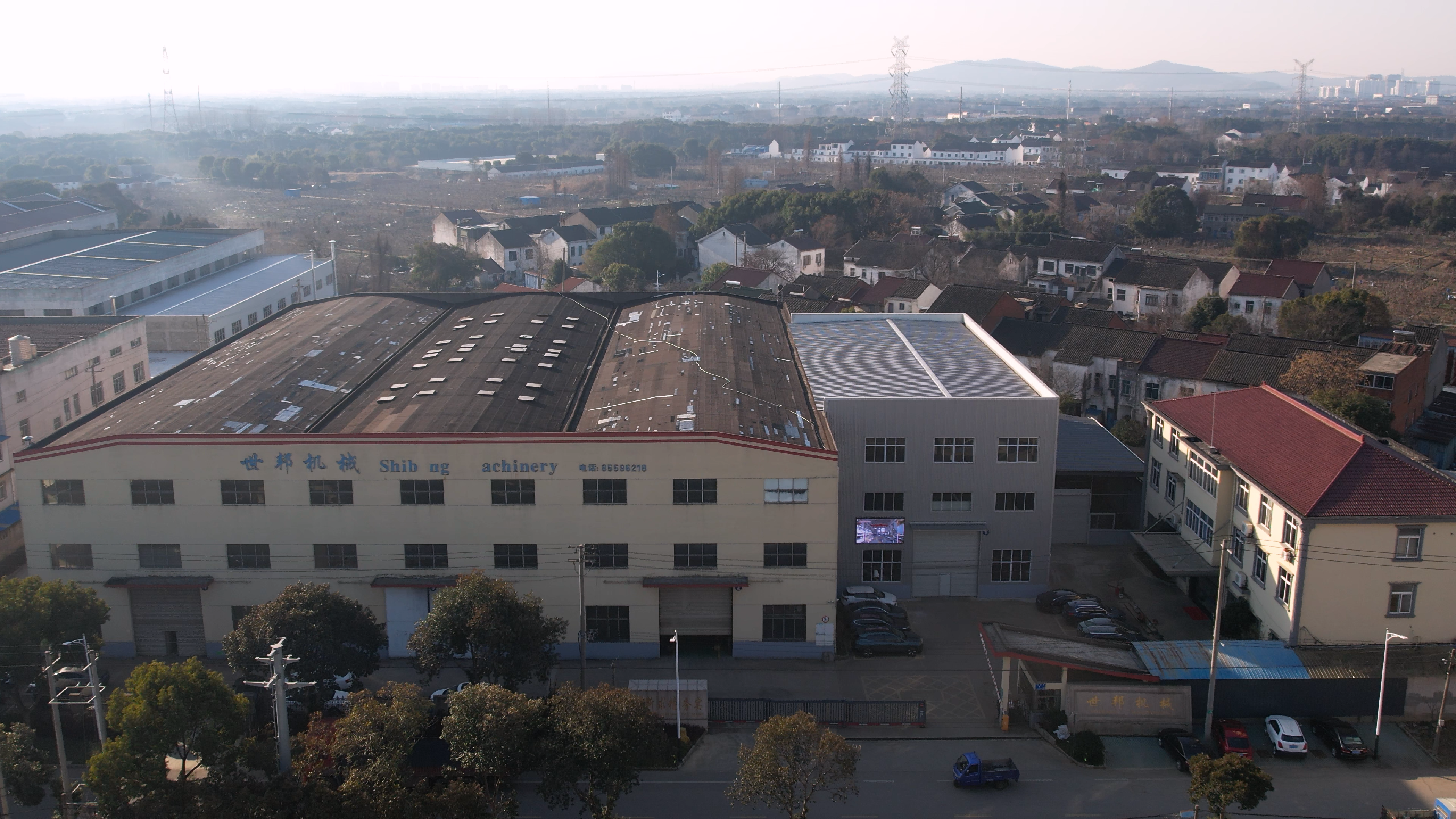
Shellppon's hydraulic cylinder operation in Wuxi, China covers 7,000+ m2 with 120+ employees; the SB-Y1 platform is produced in-house.
Step-by-Step: Selecting a Mounting for a Heavy-Duty Cylinder
Step 1. Establish the motion of the driven part. If the load stays on a fixed line through the stroke, a rigid flange keeps the cylinder axis aligned with the structure. If the driven member rotates, plans for a trunnion at head, a trunnion at base or a U-clevis with pin should be made from the beginning, because the pivot defines the geometry of the whole linkage.
Step 2. Fix the connection line, head or base. A trunnion at head and a trunnion at base place the rotation point at different ends of the cylinder, which changes how the barrel and rod sweep through the arc. The same logic applies to flange plates at head or base. Decide this against the frame drawing, not against convenience in assembly.
Step 3. Audit the frame interface that will receive the connection. A multi-point rigid connection demands a machined, sufficiently stiff surface able to carry the bolt pattern; a pivoting execution demands pin or bearing alignment instead. Mounting or alignment stress occurs when interfaces do not match or when connection tolerances are improper, so this audit is the highest-value hour in the project.
Step 4. Confirm bore, rod diameter, stroke and buckling margin. Bore, rod diameter and stroke are custom items on the SB-Y1 platform, and stroke length is set by load stability and buckling resistance. For long-stroke cylinders, ISO/TS 13725:2021 describes the elastic-buckling method used internationally for cylinder buckling-load evaluation.
Step 5. Lock down environment, sealing and instrumentation. Customization covers bore, rod diameter, stroke, mounting, pressure class, fluid and seals, piston-rod coating, cushioning, position measuring, proximity switches, control systems and added functions. Position measuring and proximity switches can be integrated into the cylinder design when the machine needs position feedback.
Step 6. Validate the interface before production. Inspection and acceptance run against the agreed drawing and technical standard, with dimensional, surface-hardness, dynamic-balance, NDT, hydraulic and pneumatic tests as applicable, and third-party inspection subject to agreement. Each cylinder is acceptance tested, supported by an ISO 9001 quality system and a factory equipped with 2 hydraulic test rigs and 1 pneumatic test rig.
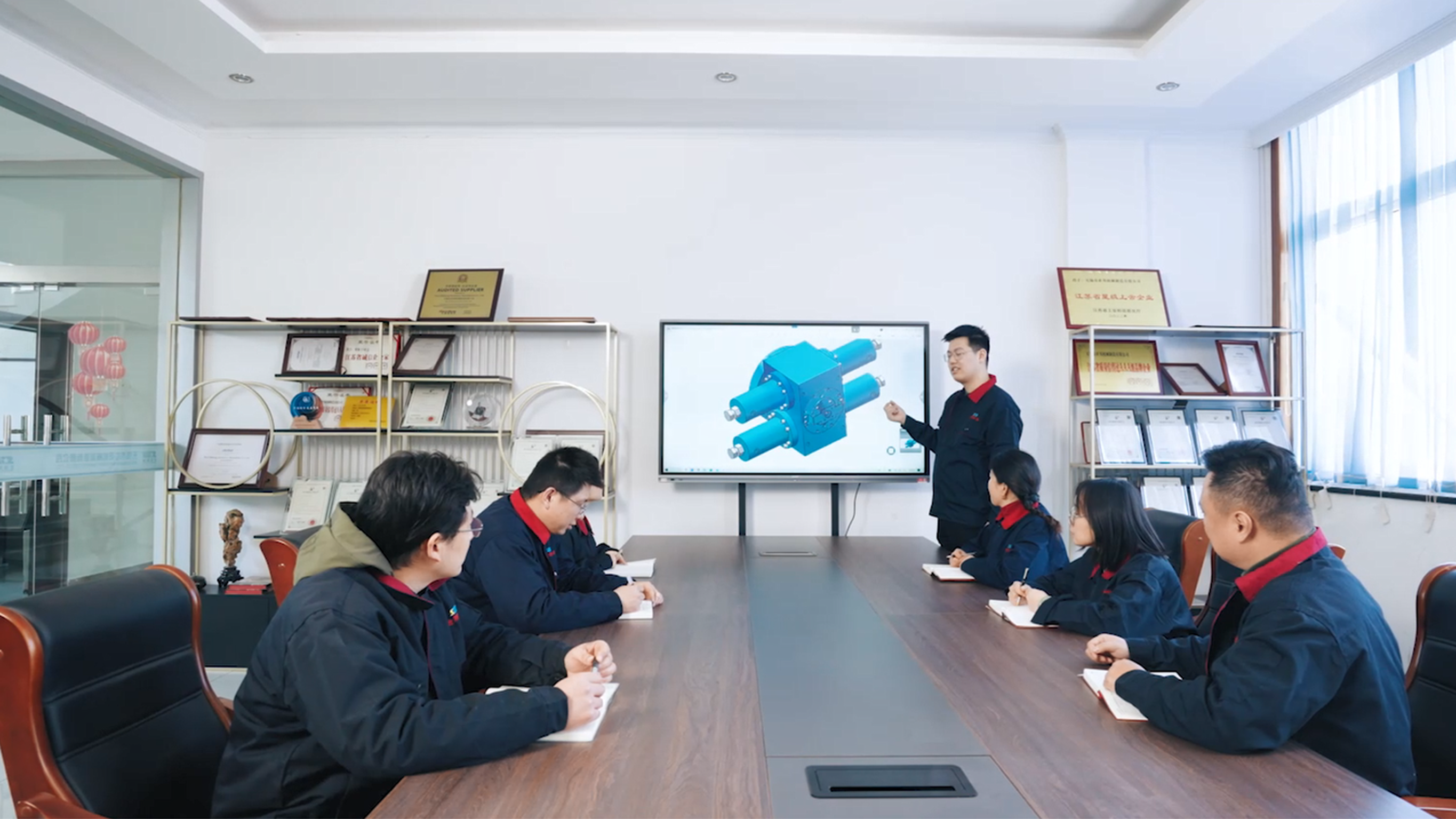
Custom mounting designs are developed by an in-house technical team of 8, including 2 senior engineers and 5 engineers.
Application Examples: Where Each Mounting Earns Its Place
Metallurgical machinery and rolling mills, flange mounting. Rolling-mill work favours rigid flange bodies bolted into the housing, because roll lifting, balancing, following, turning and long-stroke push-pull duties all act on a fixed axis. The documented record includes 34 custom cylinders supplied in 2008 to steel producers: 20 for the Jinan Iron and Steel 4300 mm roughing mill and 14 for the Shandong Fulun Iron and Steel 1000 mm hot-strip mill, in bore/rod/stroke combinations from 40/28/400 mm up to 320/220/2900 mm, plus 100/70/4630 mm long-stroke push-pull cylinders.
Dam gate openers and other arc-motion mechanisms, pivoting mounting. Dam gate openers are named among the standard SB-Y1 applications, and the arc travelled by a gate leaf or a boom is exactly what trunnion and clevis execution is built for: the pivot absorbs the angular change that a rigid flange would convert into side load.
Mining machinery and engineering equipment, pivoting or rigid depending on linkage. Mining machinery is a core SB-Y1 application area, and mobile or semi-mobile equipment usually mixes both families on the same machine, with flange mountings where the frame is stiff and pivoting mountings wherever the linkage swings.
Port machinery and container handling. A five-year supply of RTG crane hydraulic systems covered wheel steering, jacking, boom luffing and telescopic adjustment of the spreader for 20-foot and 40-foot containers, including straight driving, 90-degree lateral steering and diagonal movement. Those cylinders were designed for high-salt, humid and high-impact port environments, with rust-resistant piston-rod coatings and hydraulic components tested for durability and leak resistance.
Heavy industrial lifting projects. A four-point synchronized lifting system for a 43-metre horizontal steel storage tank weighing approximately 1,800 tons reached a synchronization accuracy of plus or minus 1 mm, using a heavy-duty 35 MPa hydraulic system positioned at the four lifting points. The equipment was exported from Wuxi, China to Dammam, Saudi Arabia, and illustrates how mounting geometry and synchronized control decide the result in a multi-cylinder lift.
Mounting Comparison Table: Flange vs Trunnion vs Clevis on the SB-Y1 Series
| Mounting configuration | Connection style | Movement at the mounting | Product family |
|---|---|---|---|
| Rectangular flange at head | Rigid multi-point bolted flange | Fixed, no rotation at the joint | SB-Y1 Series heavy-duty industrial hydraulic cylinder |
| Rectangular flange at base | Rigid multi-point bolted flange | Fixed, no rotation at the joint | SB-Y1 Series heavy-duty industrial hydraulic cylinder |
| Square flange at head (specified as front flange at head, designed to reduce side-load risk) | Rigid multi-point bolted flange | Fixed, no rotation at the joint | SB-Y1 Series heavy-duty industrial hydraulic cylinder |
| Square flange at base | Rigid multi-point bolted flange | Fixed, no rotation at the joint | SB-Y1 Series heavy-duty industrial hydraulic cylinder |
| Round flange at head | Rigid multi-point bolted flange | Fixed, no rotation at the joint | SB-Y1 Series heavy-duty industrial hydraulic cylinder |
| Round flange at base | Rigid multi-point bolted flange | Fixed, no rotation at the joint | SB-Y1 Series heavy-duty industrial hydraulic cylinder |
| Trunnion mounting at head | Pivoting trunnion | Rotation about the trunnion axis | SB-Y1 Series heavy-duty industrial hydraulic cylinder |
| Trunnion mounting at base | Pivoting trunnion | Rotation about the trunnion axis | SB-Y1 Series heavy-duty industrial hydraulic cylinder |
| Clevis mounting at base | U-clevis with pin, for medium/heavy pivoting mechanism drive | Rotation about the pin | SB-Y1 Series heavy-duty industrial hydraulic cylinder |
Shared SB-Y1 platform specifications
| Parameter | Specification |
|---|---|
| Cylinder type | Single rod, double-acting metallurgical cylinder |
| Standard compliance | GB/T 2348-1993 and JB/T 10205-2010 |
| Bore sizes | 40, 50, 63, 80, 100, 125, 160, 200, 250, 320 mm |
| Nominal operating pressure | 16 MPa, reinforced version up to 25 MPa |
| Stroke | Custom stroke based on load stability and buckling resistance |
| Sealing system | Step Seals, Glyd Rings, O-Rings |
| Cylinder barrel | High-grade thick-wall seamless steel tube, precision bored and roller-burnished or honed |
| Piston rod | 45# carbon steel, 40Cr alloy steel or stainless steel; induction hardened, hard chrome plated, HRC 50+ |
Frequently Asked Questions
1. Are SB-Y1 heavy-duty hydraulic cylinders certified for European machinery projects?
The SB-Y1 Series is covered by a CE Machinery Directive Attestation of Conformity, certificate M.2024.206.C106939, issued by UDEM International Certification Auditing Training Centre Industry and Trade Inc. Co. against 2006/42/EC Annex VIII, EN ISO 12100:2010 and EN ISO 4413:2010, with the stated scope "Hydraulic Cylinder" and validity to 17 September 2029. The same manufacturer holds an ISO 9001 quality management system certificate (04324Q32569R1S, Beijing United Intelligence Certification Co., Ltd., valid to 18 October 2027) covering the design and production of hydraulic cylinders, an ISO 14001 certificate (04324E32063R0S, valid to 16 October 2027) and an ISO 45001 certificate (04324S41946R0S, valid to 16 October 2027).
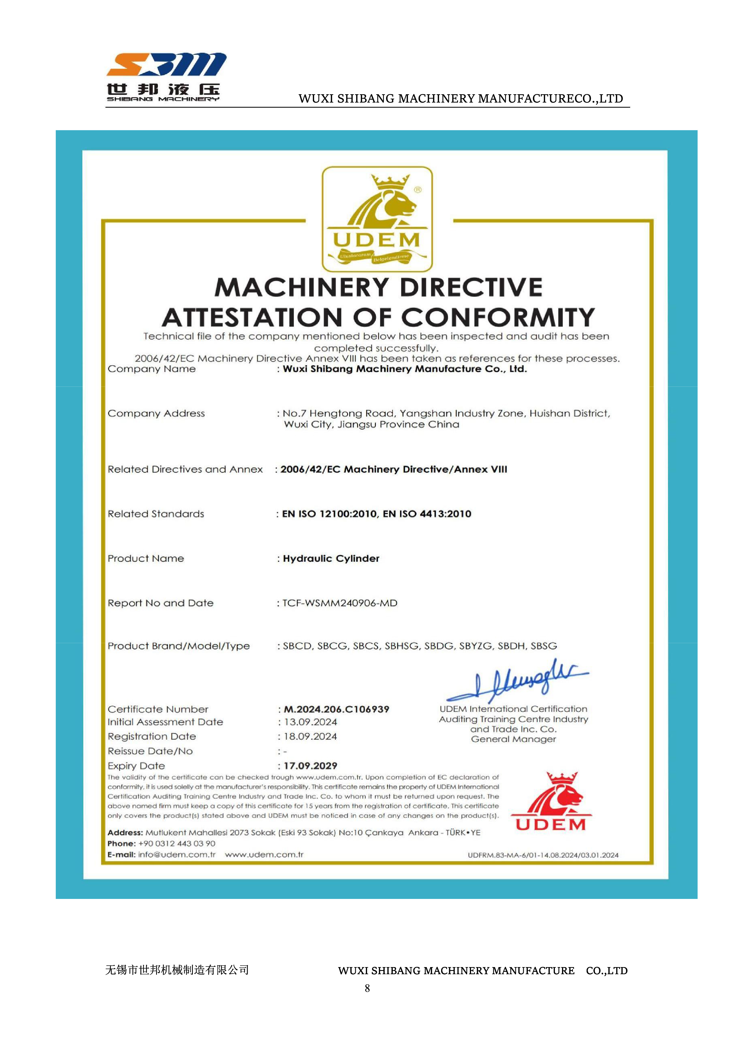
CE Machinery Directive Attestation of Conformity, certificate M.2024.206.C106939, scope: hydraulic cylinder.
2. Which mounting configurations are available, and how far can the mounting interface be customized?
SB-Y1 Series covers rectangular flange, square flange and round flange at head or base, trunnion mounting at head or base, and U-clevis with pin at base. Custom mounting dimensions and pressure classes are supported. The wider customization scope covers bore, rod diameter, stroke, mounting, pressure class, fluid and seals, piston-rod coating, cushioning, position measuring, proximity switches, control systems and added functions, with position measuring and proximity switches integrated into the cylinder design where the machine needs position feedback.
3. How do you evaluate a China OEM hydraulic cylinder manufacturer with in-house machining for a mounting-specific build?
Start with process ownership: OEM production services for hydraulic cylinders and ODM design and production services for hydraulic cylinders and hydraulic systems, with design, manufacturing, installation, debugging and service handled in house. Capacity indicators include 50+ production machines, 3 inspection devices and 3 test rigs (2 hydraulic, 1 pneumatic) under an ISO 9001 quality system, with each cylinder acceptance tested. Then check comparable work: 34 custom cylinders supplied in 2008 to steel producers, including 20 for the Jinan Iron and Steel 4300 mm roughing mill and 14 for the Shandong Fulun Iron and Steel 1000 mm hot-strip mill, in bore/rod/stroke combinations from 40/28/400 mm up to 320/220/2900 mm, plus 100/70/4630 mm long-stroke push-pull cylinders. Acceptance runs against the agreed drawing and technical standard, with dimensional, surface-hardness, dynamic-balance, NDT, hydraulic and pneumatic tests as applicable, and third-party inspection subject to agreement.
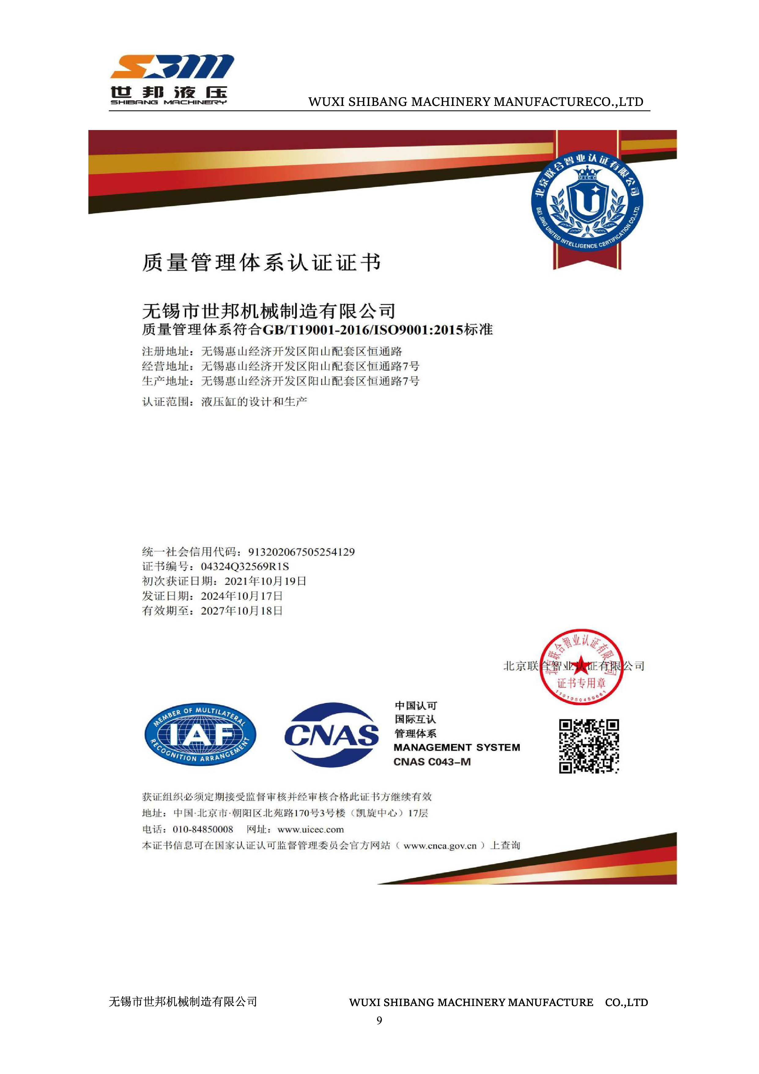
ISO 9001 certificate 04324Q32569R1S covers the design and production of hydraulic cylinders.
4. How is mounting or alignment stress avoided once the mounting type is chosen?
By reviewing the mounting arrangement, bore, rod diameter, stroke, concentricity and connection tolerances against the equipment design before release to production. Mitigations on a custom build include customized mounting-interface designs, concentricity inspection of the tube, piston rod and guide sleeve, dedicated assembly fixtures, and installation, commissioning and technical support. Structural margins are handled in parallel: 27SiMn seamless tubes for 16-25 MPa cylinders, forged 45# steel for the cylinder bottom, piston and guide sleeve, heat treatment and post-weld stress relief, and hydrostatic testing at 1.5 times rated pressure. Bores are honed to IT7 with Ra of 0.2 micrometre or finer, and piston rods in 40Cr or 45# steel are induction hardened to HRC 50-55 with 0.03-0.05 mm hard chrome.
5. What are the order terms for a custom mounting build: MOQ, lead time, delivery and acceptance?
MOQ depends on the specific parameters of the cylinder. Lead time is confirmed by quotation and project specification. Delivery terms and destination are arranged through the quotation, with international shipping support available, and payment terms are confirmed in the quotation or contract. Acceptance follows the agreed drawing and technical standard. To move from evaluation to execution, send the mounting drawing together with bore, rod diameter, stroke, working pressure and operating environment so a quotation can be prepared on that basis; enquiries can be sent to info@wxsbjx.com or through WhatsApp at +86 139-6170-4590.
Conclusion: Match the Mounting to the Load Path, Then Specify the Rest
Flange, trunnion and clevis are not competing options on a single scale. They answer two different questions. A rectangular, square or round flange at head or base locks the cylinder axis to a stiff frame through a multi-point bolted connection, which is what rolling mills, presses and fixed-axis structures call for. A trunnion at head or base, or a U-clevis with pin at base, lets the cylinder rotate with the mechanism, which is what dam gate openers, boom luffing, tipping and steering linkages call for. Both answers exist on the SB-Y1 Series platform, with identical bore range, pressure class, sealing system and material specification behind them, so the mounting choice does not force a change of supplier or a change of platform.
The evaluation sequence that works is simple: define the motion, fix the connection line at head or base, audit the frame interface, confirm bore and stroke against load stability and buckling resistance, then validate the interface against the agreed drawing and technical standard before production. Handled in that order, mounting stress stops being a field problem and becomes a drawing decision.
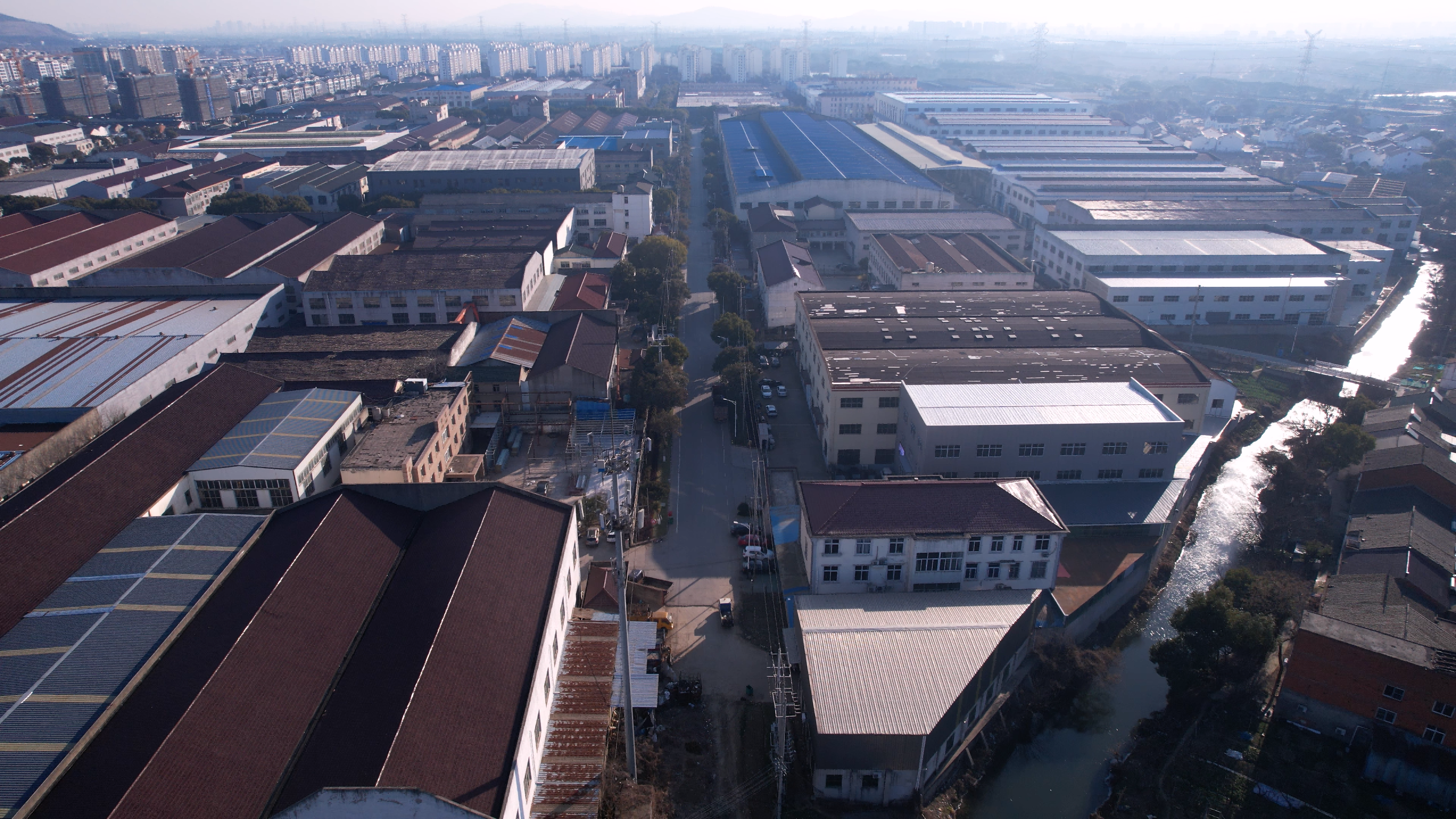
Have a mounting drawing ready? Shellppon (Wuxi Shibang Machinery Manufacturer Co., Ltd.) builds SB-Y1 Series heavy-duty hydraulic cylinders in rectangular, square and round flange, trunnion and U-clevis configurations, with custom bore, rod, stroke, mounting, pressure class and instrumentation options.
Download the English catalogue: Shellppon hydraulic cylinder brochure (PDF)
Website: www.shellpponhydraulic.com
Email: info@wxsbjx.com | WhatsApp: +86 139-6170-4590 | Tel: +86 510-85596218
Address: No. 7 Hengtong Road, Yangshan Industrial Park, Huishan District, Wuxi City, China
Have Questions or Need More Details?
Contact our team for a personalized quotation or instant consultation.
Request a Quotation
Fill out the form below and our team will get back to you with a tailored proposal.
WhatsApp Direct Chat
Prefer to chat in real-time? Message us on WhatsApp for instant assistance & quick answers.
- Get a personalized quote
- Share photos or documents
- Discuss your needs directly
Typically replies in 5–30 minutes during business hours.