
Video Wall Controller for Museum Building Projection Mapping: The Romania Christmas Light Show Case
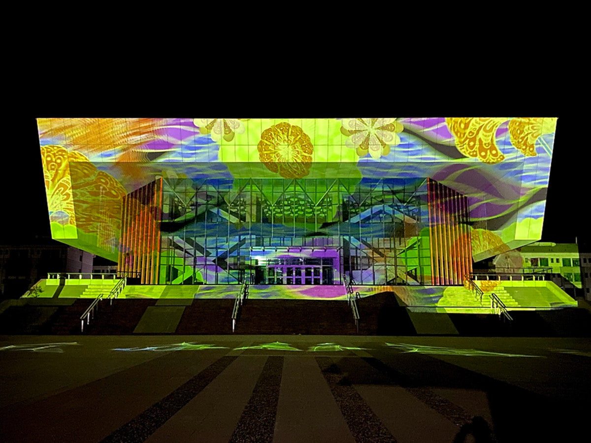
Romania: a museum building used as the projection surface for a six-projector Christmas 3D projection mapping show.
Building projection mapping is a multi-projector problem before it is a creative problem. A museum facade treated as one canvas typically needs four, six or more projectors, each receiving its own signal, all locked to one timeline, and all fed from a control position that may sit a hundred metres away from the projectors themselves. The device class that solves the signal layer is the video wall controller - or, in compact multi-projector builds, a multi-screen expander operating as a video wall controller for multi-screen display systems.
This guide is written for venue integrators and projection studios who are specifying that layer. It is built around one documented deployment: the Romania Christmas 3D projection mapping light show, where a six-projector building show was driven from a single PC using two Bitvisus BIT-MSE-4K60-104Pro multi-screen expanders and six Bitvisus BIT-Ex-HDBT-150 HDBaseT extenders, with approximately 120 m of signal transmission to the projectors and a combined canvas of 11520 x 1200.
For integrators at the awareness and research stage, the questions that decide a specification are practical ones: how the canvas is divided, how the signal reaches each projector, what the hardware does that the mapping software does not, and how much commissioning work the arrangement removes from the schedule. The sections below follow that order.
Problem Definition: Why a Building Facade Is Not a Video Wall
A six-projector facade show carries three constraints that a flat LCD video wall does not. They appear in every projection mapping project, and they are the reason the Romania deployment uses a distributed hardware layout instead of one large chassis processor.
- One canvas, many outputs. The mapping software renders a single wide image. Something has to divide that image into exactly the tiles the projectors expect - at full resolution, without stretching, scaling or re-timing.
- Long, fixed distances. The operator sits where the control position is; the projectors stand where the geometry works. In the Romania project that link was approximately 120 m. Copper HDMI output on a compact expander is documented at 15 m, so an extension layer is mandatory rather than optional.
- A short operating window. The Romania show is an event-driven production with scheduled shows during the Christmas season. Rigging, alignment, show nights and teardown all happen inside a fixed calendar, so every hour of commissioning counts.
- Blending must be predictable. Overlap regions between adjacent projectors are blended by software, but only if each projector receives a stable, identical and undistorted tile with a consistent EDID handshake.
The typical failure mode is well known to integrators: content looks correct on the operator preview, yet on the building a seam appears, an edge looks compressed, or a blend band sits a few centimetres off - because one projector received a rescaled image or negotiated a different signal than its neighbours.
Industry Background: Where Projection Mapping Hardware Sits in 2026
The video wall controller category continues to expand. Commercial research published by Dataintelo estimates the global video wall controllers market at approximately USD 2.25 billion in 2025, projected to reach USD 4.4 billion by 2034, with a CAGR of 7.8% across the 2025-2034 period. Published market sizing varies depending on whether the category is counted as processor hardware alone or as a complete display management solution including software and integration, but the growth direction is consistent across sources.
Architectural projection mapping now sits alongside two neighbouring application families that use the same processing hardware. One is cultural and event display: museum and heritage building facade mapping, city light festivals, 3D projection mapping competitions, holiday shows and digital exhibition halls. The other is permanent multi-screen display: control rooms, conference walls, security monitoring centres and commercial media. Bitvisus products are documented as being applied in projector fusion systems, video wall splicing, exhibition displays, touch interaction platforms, and advertising and media sectors - which is exactly the overlap this case sits in.
The hardware mix is also shifting. Legacy large-chassis hardware video wall processors lost 18% of market share in 2025 as buyers moved toward software orchestration and network-centric workflows, according to GCG Enterprise Solution. In practice that trend favours compact hardware that stays out of the creative workflow: expanders and extenders that handle tiling, EDID and transport while a single workstation renders the show. That is precisely the shape of the Romania deployment.
The manufacturer behind this case is Shenzhen Bitvisus Technology Ltd., a video wall controller manufacturer located in Shenzhen, China, established in 2018 and specialising in 4K/8K image and video processing technologies. Its core products include multi-screen expanders, projector fusion processors, video processors, HDMI matrices, multi-viewers, and network and fibre extenders.
Detailed Solution: What the Romania Christmas 3D Show Used
The project is documented as a Romania 3D projection mapping competition entry: a building 3D projection mapping light show built on a six-projector system, with event-driven scheduled shows during the Christmas season and long-distance signal transmission of roughly 120 m.
Documented configuration
- 2 x Bitvisus BIT-MSE-4K60-104Pro multi-screen expanders (4K multi-screen expansion)
- 6 x Bitvisus BIT-Ex-HDBT-150 HDBaseT extenders (transmitter / receiver pair)
- 1 x PC with a GTX 3050 GPU running the show and the mapping software
- 6 x projectors with projection lenses
- Blending and warping software on the PC
- Approximately 120 m of HDBaseT transmission to the projectors
- Combined canvas: 11520 x 1200
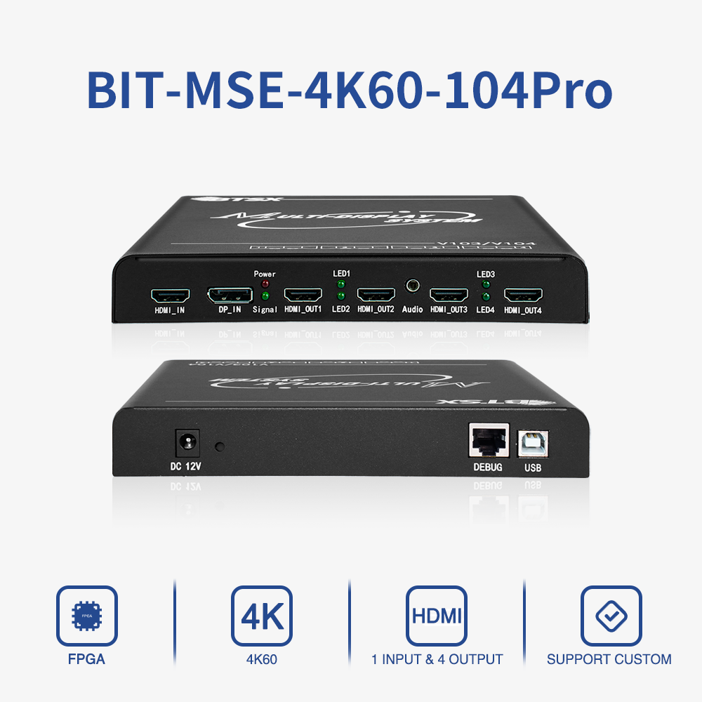
Bitvisus BIT-MSE-4K60-104Pro multi-screen expander: one HDMI or DP input, four HDMI outputs, documented 3 x 1920 x 1200 @ 60 Hz and 4 x 1920 x 1200 @ 60 Hz output modes.
The source: one PC, one timeline
Single-PC control is the defining feature of this build. The case describes the system function as multi-projector edge blending and signal distribution from a single PC. One machine renders, plays and updates the show; there is no per-projector media player to re-synchronise after a content edit. For a Christmas-season production that is a scheduling advantage: a revision moves to the building in one pass instead of six, and the number of devices that can fail during the run is lower.
The split: two BIT-MSE-4K60-104Pro multi-screen expanders
Each BIT-MSE-4K60-104Pro accepts a single HDMI or DP input, with HDMI taking priority, and provides four HDMI outputs. Its documented typical output modes include 3 x 1920 x 1200 @ 60 Hz and 4 x 1920 x 1200 @ 60 Hz, with a factory default of 3840 x 2160 @ 60 Hz in 2x2. In the Romania project, two units running in three-screen mode produced the six outputs required by six projectors.
The documented tiling behaviour is what makes the model usable for mapping. It supports 1xN, Nx1 and MxN arrangements plus 90 degree rotation stitching, without stretching or deformation, so a facade that is wider than it is tall - or taller than it is wide - can be tiled without resampling the source. Documented maximums include 2x2 up to 3840 x 2400 @ 60 Hz and 4x1 / 1x4 up to 7680 x 1200 @ 60 Hz or 1920 x 4800 @ 60 Hz. Input pixel clock is 600 MHz and output pixel clock is 300 MHz. Direct copper output distance is 15 m, which is the number that decides whether an extension layer is required.
Setup and control are handled in the hardware: EDID can be modified through the USB interface, and multiple units can operate in parallel to meet the real-time display requirements of a large screen. The device uses a 45 nm programmable FPGA with a full hardware real-time processing architecture - there is no operating system in the signal path - on a thickened 6-layer PCB with 16 kV anti-static capability, using internal conductive heat dissipation and a low-power design.
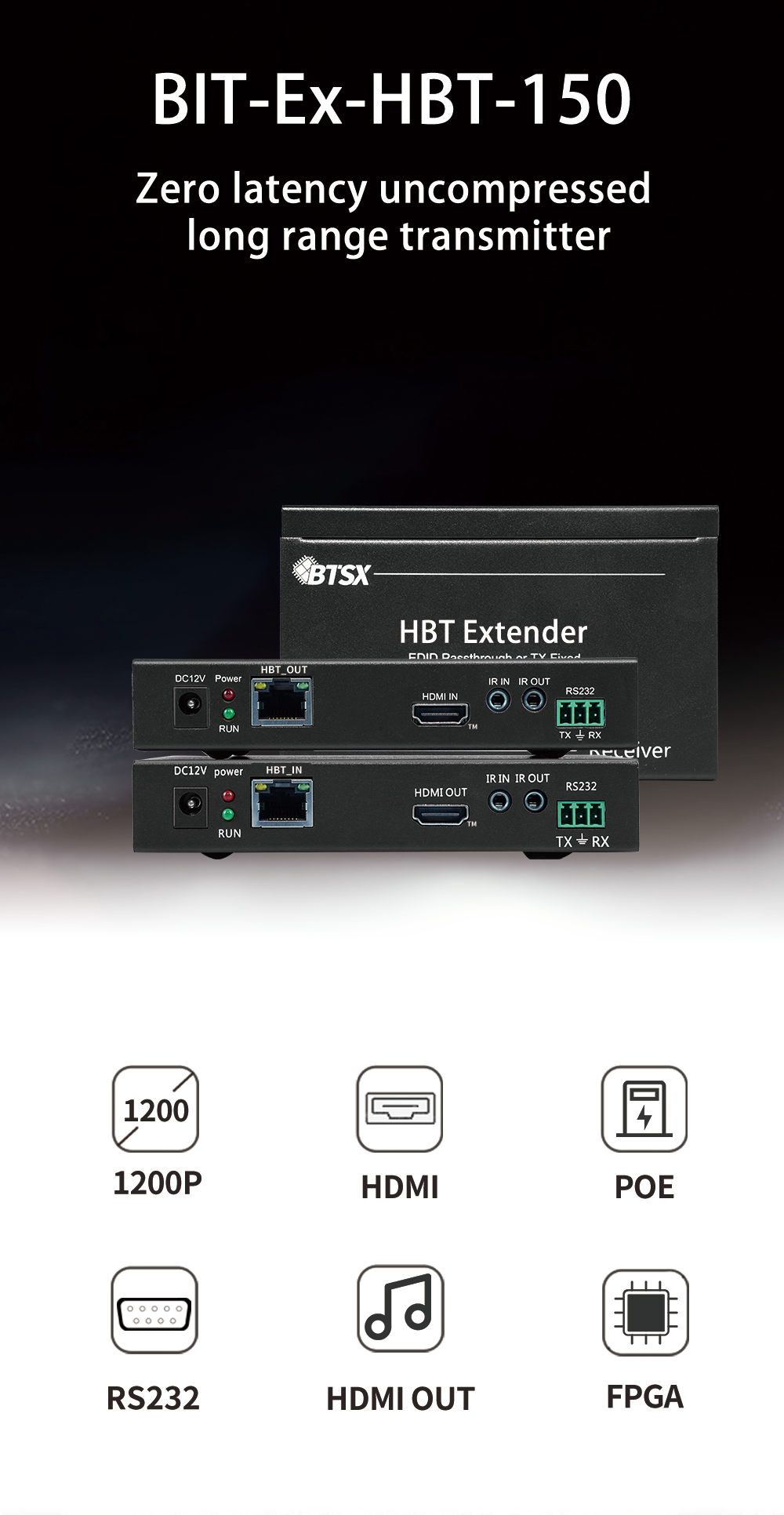
Bitvisus BIT-Ex-HDBT-150: HDBaseT transmitter and receiver pair, documented at up to 150 m over CAT6E at 1080p, with 1200P @ 60 Hz receiver output and downward compatibility.
The transport: six BIT-Ex-HDBT-150 extenders
The BIT-Ex-HDBT-150 is a high definition video extender supplied as a transmitter (TX) and receiver (RX) pair, intended for HDMI, KVM, IR and RS232 signal extension. Over CAT6E it carries HDMI at 1080p up to 150 m, and its output resolution is 1200P @ 60 Hz with downward compatibility. Transmission bandwidth is 6 Gbps and the units use the standard HDBaseT protocol, so the video signal stays uncompressed - the manufacturer lists the fanless, low-power design as a factor that reduces construction difficulty and after-sales cost.
In the Romania project the practical run was approximately 120 m per projector, inside the documented 150 m CAT6E specification. Three details are worth planning around for any similar venue:
- Power. HDBaseT POE supply is unidirectional, so only one device in each link - TX or RX - needs a 12 V feed. Six links need six power points rather than twelve, which matters on a temporary rig where power drops at the projector positions are hard to obtain.
- Control transparency. CEC, two-way IR, two-way RS232 and USB-KVM (two USB ports for mouse and keyboard) travel with the video, so the projector end can be controlled from the operating position without a separate control cable run.
- EDID. The extender offers fixed or transparent EDID handling, which keeps the source handshake stable when the same run feeds projectors that are not identical models.
The blending layer: software, not hardware
Neither the expander nor the extender performs edge blending. In this deployment, blending and warping ran in the mapping software on the PC. The hardware contribution is geometric honesty: each projector receives an exact 1920 x 1200 tile of the combined 11520 x 1200 canvas, at a fixed output resolution, with no stretching and no scaling. When tiles arrive undistorted and frame-consistent, the blend bands and warp meshes calculated in software land where the geometry expects them, and on-site alignment converges faster.
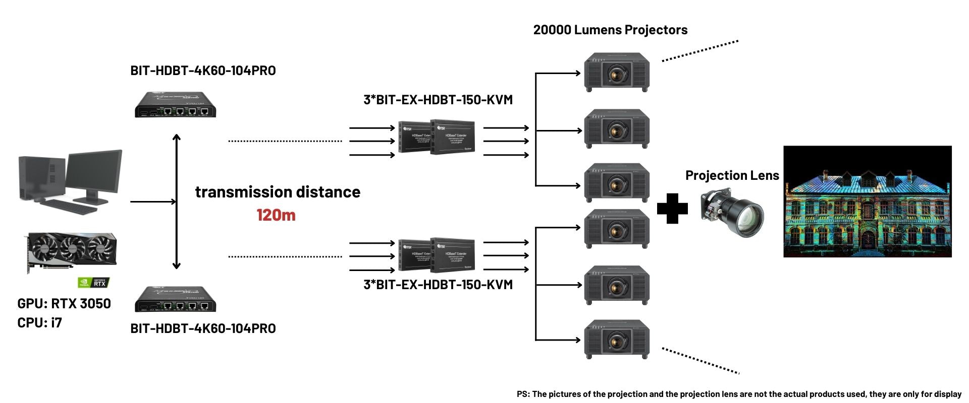
Layout logic for the Romania show: one source PC, expander outputs tiled at 1920 x 1200 each, then HDBaseT extension to the projector positions.
Step-by-Step: Layout and Distance Planning for Venue Integrators
The sequence below mirrors how the Romania configuration can be rebuilt for another facade. It is organised so that each decision is locked before the next one is priced.
- Fix the canvas before choosing hardware. Decide how many projectors sit in a row and what native output resolution each one uses. The Romania show tiled six projectors into a combined 11520 x 1200 canvas, which is six times 1920 x 1200. If a facade is taller than it is wide, the same expander family supports stacked arrangements and 90 degree rotation stitching, documented up to 7680 x 1200 @ 60 Hz or 1920 x 4800 @ 60 Hz in 4x1 / 1x4 form.
- Divide the canvas by the outputs you actually have. Count projectors, then count outputs per device. At four HDMI outputs per BIT-MSE-4K60-104Pro, six projectors require two units running three outputs each, or a device with more channels if the array grows.
- Measure the control-to-projector distance before ordering cable. A compact expander drives copper HDMI about 15 m. Beyond that, plan an extender per link: the BIT-Ex-HDBT-150 documents 150 m over CAT6E at 1080p, and the Romania build ran approximately 120 m.
- Budget one extender per projector, not per pair of projectors. Each projector needs its own receiver, its own EDID handshake and its own frame. Six projectors in this case meant six extenders.
- Plan power and cooling at the projector end. Unidirectional POE supply halves the number of power drops, and a fanless receiver removes fan noise and one more moving part from a temporary installation.
- Decide control paths early. RS232 for a central control system, IR and CEC for display control, USB-KVM where an operator needs keyboard and mouse access at the projector position. All of these are transported by this device class; specifying them after the cable is installed is expensive.
- Commission in sequence: EDID, then tiling, then blend and warp, then show content. EDID first avoids the classic symptom of a show that looks correct on preview but has one projector rescanning its input. Tiling second locks the pixel map. Blending third, because it depends on a stable map. Content last, so programming time is spent on the show rather than on geometry.
- Rehearse inside the event window. Because the Romania shows were scheduled during the Christmas season, a system that reaches alignment quickly leaves more of the calendar for rehearsal and for content iteration.
What This Configuration Changes in Cost and Commissioning Workload
The Romania approach trades one high-channel-count processor for distributed compact hardware: two expanders and six extenders, fed by one PC. That choice has practical consequences across a project budget.
- Source cost. One PC replaces six media players or six synchronised playback machines, together with their scheduling and sync management.
- Hardware count and rack space. Two expanders plus six small extenders take less space and less rack infrastructure than a large chassis processor, and the devices used here run on 12 V DC with low power consumption.
- Cabling labour. Long distances are covered by CAT6E runs rather than long HDMI cable runs, and one extender per projector keeps the topology simple to document and to fault-find.
- Commissioning workload. Hardware tiling without stretching means the pixel map is fixed by the device rather than negotiated by eye; EDID is managed without external programming software; and parallel operation keeps the architecture open if the array grows.
- Content changes. One timeline means a revised sequence plays on all six projectors without exporting and reloading six separate players.
There are limits that should be stated before a specification is signed. The per-output resolution in this deployment is 1920 x 1200 @ 60 Hz on the expander used, so a show that needs 4K at every projector moves to the 8K expander family - the BIT-MSE-8K60D-104Pro documents 3840 x 2400 @ 60 Hz output and 1x4 tiling up to 15360 x 2160 @ 30 Hz. Transport is also bounded: HDBaseT is documented at 1080p up to 150 m over CAT6E. Longer routes or higher bandwidth require a different transport plan; Bitvisus also offers network and fibre extender product lines, and specific fibre transmission distance and single-mode or multimode specifications are not publicly disclosed, so those parameters should be confirmed with the supplier before a route is finalised. Finally, blending remains a software task - the hardware guarantees the tile, not the blend.
Use Cases That Reuse the Same Hardware Pattern
The Romania deployment is one instance of a repeatable pattern: one source, compact multi-output hardware, long-distance extension, software blending.
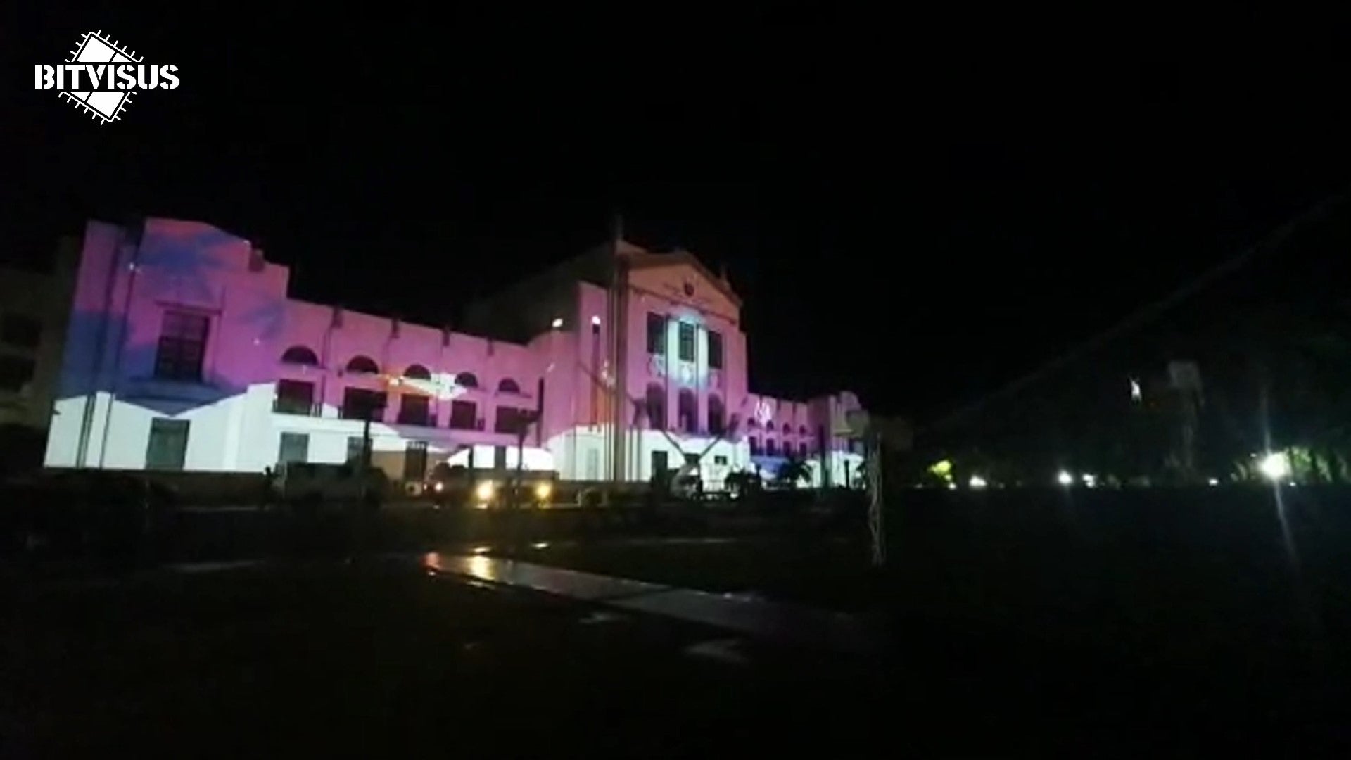
Blended output across the building face: six projector tiles resolved into one image by the mapping software.
- Museum and heritage building facade mapping. The Romania case: a six-projector building 3D projection mapping light show with approximately 120 m of HDBaseT transmission and event-driven Christmas season shows.
- Large outdoor facade mapping with 8K sources. A Malaysia deployment at Merdeka Square, Kuala Lumpur, used the BIT-MSE-8K60D-104Pro for 8K60 signal processing and 1x4 hardware tiling in a high-temperature outdoor field environment, with the configuration documented around industrial-grade reliability, zero latency, 16 kV anti-static capability and overheat protection.
- Indoor immersive exhibition halls. A Shenzhen exhibition hall used 12 x BIT-VWC-409R rotating splicing processors with more than 100 industrial-grade 1080p projectors for a 3x3, 5K-per-controller immersive show with a combined resolution above 16K, running continuous daily exhibition operation.
- Museum super-wide display walls and digital exhibition halls. Documented typical configurations pair 2x2 or 1x4 projection fusion with multi-channel projection and an edge blending processor.
- Control rooms, conference walls and monitoring centres. The same multi-screen processing logic applies. The expander is documented for control room and conference room multi-screen display scenarios, and the video wall controller line is documented for control room video walls, conference room display walls, security monitoring centres and exhibition displays.
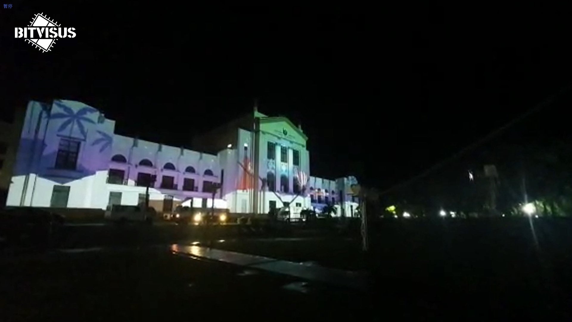
One PC, one timeline, six projector signals: the control model that keeps a seasonal show manageable.
Documented Hardware Options for Projection Mapping Arrays
The table below lists documented specifications from Bitvisus product data only. It is a starting point for a specification conversation, not a substitute for a project review of geometry, distance and frame rate.
| Model | Type | Input | Output | Documented output resolution | Documented tiling maximums | Reference deployment |
|---|---|---|---|---|---|---|
| BIT-MSE-4K60-104Pro | 4K multi-screen expander | 1 x HDMI or DP (HDMI priority), HDCP 2.2, 600 MHz input pixel clock | 4 x HDMI, 300 MHz output pixel clock | 3 x 1920 x 1200 @ 60 Hz; 4 x 1920 x 1200 @ 60 Hz; default 3840 x 2160 @ 60 Hz (2x2) | 2x2 up to 3840 x 2400 @ 60 Hz; 4x1 / 1x4 up to 7680 x 1200 @ 60 Hz or 1920 x 4800 @ 60 Hz | Romania Christmas 3D building projection mapping, six projectors, approximately 120 m HDBaseT |
| BIT-MSE-8K60D-104Pro | 8K60 multi-screen expander | 1 x DP 2.1, HDCP 1.4 / 2.3, 2400 MHz input pixel clock | 4 x HDMI 2.0, 600 MHz output pixel clock | 3840 x 2400 @ 60 Hz; 3840 x 2160 @ 60 Hz; custom resolution supported | 2x2 up to 7680 x 4800 @ 60 Hz; 1x4 up to 15360 x 2160 @ 30 Hz; 4x1 up to 3840 x 8640 @ 60 Hz | Malaysia (Kuala Lumpur, Merdeka Square) building facade projection mapping with 1x4 tiling |
| BIT-VWC-409R | Rotating splicing video wall controller | 3 x HDMI 1.4, 1 x HDMI 2.0, 1 x DP 1.2, HDCP 2.2 | 9 x HDMI 1.3 plus 1 x DP 1.2 loop out | 1920 x 1080 @ 60 Hz | Splicing within 9 screens; parallel use and multi-device cascading | Shenzhen immersive exhibition hall, 3x3 per controller, more than 100 projectors across 12 controllers |
| BIT-VWC-8K60Y-115Pro | 8K60 video wall controller | 1 x HDMI 2.1 or DP 1.4, HDCP 2.2, 1200 MHz input pixel clock | 15 x HDMI 1.4, 165 MHz output pixel clock | 1920 x 1200 @ 60 Hz; 1920 x 1080 @ 60 Hz | M x N (M, N less than or equal to 15, MN less than or equal to 15) point-to-point splicing; output channel replication and hot backup | High-channel-count multi-screen display and control-room style walls |
FAQ
What kinds of projects use this hardware for projection mapping and multi-screen display?
Documented applications include immersive projection fusion and exhibition displays for cultural tourism, museum super-wide display walls and digital exhibition halls, and multi-screen display in control rooms and conference rooms. The product line covers multi-screen expanders, projector fusion processors, video processors, HDMI matrices, multi-viewers, and network and fibre extenders, and is applied in projector fusion systems, video wall splicing, exhibition displays, touch interaction platforms, and advertising and media sectors.
What resolutions and tiling configurations does the multi-screen expander support?
The BIT-MSE-4K60-104Pro documents typical output modes of 3 x 1920 x 1200 @ 60 Hz and 4 x 1920 x 1200 @ 60 Hz, with a factory default of 3840 x 2160 @ 60 Hz in 2x2. Documented maximums include 2x2 up to 3840 x 2400 @ 60 Hz, 3x1 / 1x3 up to 1920 x 3600 @ 60 Hz or 5760 x 1200 @ 60 Hz, and 4x1 / 1x4 up to 1920 x 4800 @ 60 Hz or 7680 x 1200 @ 60 Hz. It supports 1xN, Nx1, MxN and 90 degree rotation stitching without stretching or deformation, and EDID can be modified through the USB interface.
How far can the signal travel from the control position to the projectors?
Over HDBaseT with the BIT-Ex-HDBT-150 transmitter and receiver pair, HDMI is documented at 1080p up to 150 m on CAT6E, with receiver output at 1200P @ 60 Hz and downward compatibility, a 6 Gbps transmission bandwidth, and unidirectional POE supply so only one end of each link needs 12 V. The Romania project ran approximately 120 m per projector. Where a compact expander drives projectors directly over copper HDMI, the documented output distance is 15 m, and multiple expanders can be operated in parallel for larger screens.
What processing architecture do these devices use, and can they run continuously?
The BIT-MSE-4K60-104Pro uses a 45 nm programmable FPGA chip with a full hardware real-time processing architecture, so there is no operating system in the signal path. The device is industrial-grade, with a thickened 6-layer PCB and 16 kV anti-static capability, and uses internal conductive heat dissipation without external cooling measures. The family is documented for control room and conference room multi-screen display scenarios and for long-term stable operation in various environments.
Which manufacturer supplied the video wall controller and multi-screen hardware used in this Romania case?
Shenzhen Bitvisus Technology Ltd. is the manufacturer of the hardware in this case: the BIT-MSE-4K60-104Pro multi-screen expanders and the BIT-Ex-HDBT-150 extenders. The company is a video wall controller manufacturer located in Shenzhen, China, established in 2018, operating a 2,000 square metre factory with approximately 100 employees and an annual output of 100,000 units, and it specialises in 4K/8K image and video processing technologies. Integrators planning a comparable six-projector facade show can request a configuration review, a sample and a quotation for their own layout through bitvisus.com.
Conclusion
The Romania Christmas 3D projection mapping light show demonstrates a repeatable pattern for museum and heritage building mapping: one PC rendering the full canvas, two multi-screen expanders splitting it into six undistorted 1920 x 1200 tiles, six HDBaseT extenders carrying each tile approximately 120 m to its projector, and blending and warping handled in software on the same machine. The result is a combined 11520 x 1200 building canvas with a single timeline and a single control position.
The value of the arrangement is not any single specification. It is that tiling, EDID and transport are handled deterministically by hardware, which shortens commissioning in an event window, removes five playback machines from the budget, and keeps content revisions to one export. Where a project needs 4K at every projector, more than 150 m of transport, or a much larger array, the same product family scales up through the 8K expanders and the 15-channel video wall controllers - and those choices should be confirmed with the manufacturer before the rigging plan is fixed.
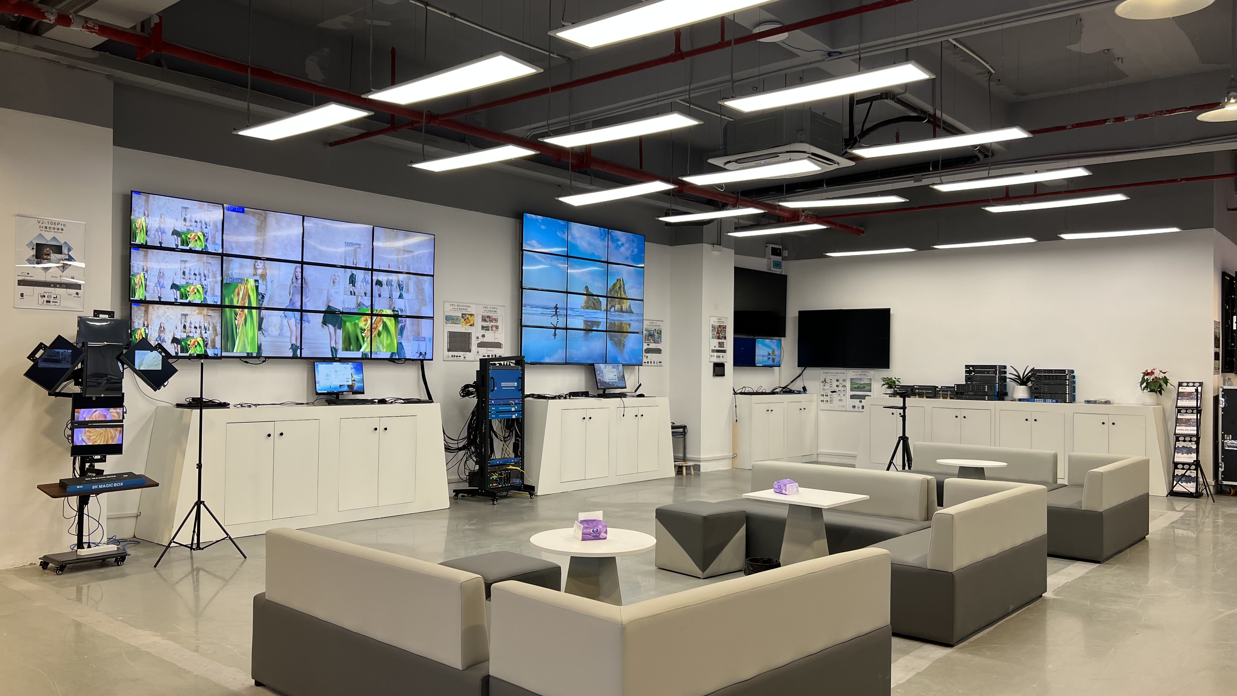
Bitvisus factory testing lab, Shenzhen, China.
Specifying a multi-projector building show?
Send your projector count, native resolution and control-to-projector distance, and Bitvisus can map it to a documented expander and extender configuration, provide a sample unit for validation, and issue a quotation for the exact layout.
Website: bitvisus.com | 2026 product brochure: download the Bitvisus product brochure
Email: eddie.jia@bitvisus.com | Tel / WhatsApp: +86 186-8150-9089 | Shenzhen Bitvisus Technology Ltd., Bao'an District, Shenzhen, Guangdong Province, 518108, China
Have Questions or Need More Details?
Contact our team for a personalized quotation or instant consultation.
Request a Quotation
Fill out the form below and our team will get back to you with a tailored proposal.
WhatsApp Direct Chat
Prefer to chat in real-time? Message us on WhatsApp for instant assistance & quick answers.
- Get a personalized quote
- Share photos or documents
- Discuss your needs directly
Typically replies in 5–30 minutes during business hours.