Industrial Lubrication Pump Basics for Smart Manufacturing: Positive Displacement Explained
Industrial Lubrication Pump Basics
An industrial lubrication pump is a positive displacement machine that draws oil from a reservoir and pushes a defined volume of it into bearings, gear meshes, guideways or hydraulic circuits on every revolution. Because the volume delivered per revolution is fixed by the pump's geometry rather than by downstream pressure, the pump keeps feeding the friction pairs even as system resistance changes — which is exactly what continuous, lightly manned production equipment requires.
This article explains the positive displacement principle behind most industrial lubrication pumps, then uses the DEO DK series low-noise helical external gear pump as a reference design to show how that principle is realised in hardware. It closes with installation rules, application notes, a comparison of pump types and a short selection scorecard.
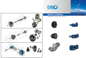
DEO electric lubrication pumps used in centralised lubrication and hydraulic supply circuits.
What an Industrial Lubrication Pump Has to Solve
A lubrication pump exists to keep a separating oil film between two surfaces that are sliding, rolling or meshing under load. In a gearbox, that film sits in the contact zone of the tooth flanks. In a bearing, it sits between the rolling elements and the raceway. In a hydraulic cylinder or a machine-tool guideway, it sits between surfaces that are alternately loaded and unloaded.
The film is thin and it is consumed. Oil is pushed out of the contact by load, it thins as temperature rises, it oxidises and forms deposits, and some of it is carried away by leakage and return flow. If fresh oil does not arrive at the same rate, the film collapses and the surfaces move from full-film lubrication into boundary or mixed lubrication.
Two failure modes, not one
- Under-supply — metal-to-metal contact, adhesive wear, scuffing, pitting fatigue, a sharp rise in friction heat, faster oil oxidation and sludge formation.
- Over-supply — churning losses, unnecessary heat generation, foaming, seal loading and leakage, plus oil mist in the working environment.
Manual greasing, oil-bath immersion and splash lubrication all deliver oil, but none of them delivers a repeatable, metered quantity per unit of machine running time. On a line that runs unattended through three shifts, or on a wind turbine gearbox that cannot be reached without a service team, unrepeatable delivery is the weak point. A positive displacement pump closes that gap: the quantity delivered becomes a function of revolutions, and revolutions become a function of time.
Why Smart Manufacturing Raises the Bar for Lubrication Pumps
Smart manufacturing changes what a lubrication pump is asked to do. When a line runs with fewer operators, the pump can no longer depend on someone noticing a noise change or a low oil level. When equipment runs continuously, duty cycles lengthen. When vibration and temperature data are collected for condition monitoring, the pump itself must stop being the most frequent unscheduled stop on the asset.
Three practical expectations follow from that:
- Continuous duty with stable delivery. The pump must hold its flow over long running periods without drifting, and it must be protected against overpressure inside its own housing.
- Low noise. Gear pumps with straight-cut gears produce a pronounced meshing tone. On a production floor with acoustic monitoring, or inside a wind turbine nacelle, that tone is a measurable nuisance.
- Tolerance of real oil conditions. Thin hydraulic oil and heavy lubricating oil can appear in the same plant, and oil cleanliness is not always what the datasheet assumes.
What the published record shows
Directional market indicators support the shift toward automatic and electric lubrication. One commercial research compilation estimates that 67% of newly commissioned industrial machines in 2024 were equipped with automatic lubrication systems, and separately forecasts the electric lubrication pump segment reaching USD 2.7 billion by 2032 at a CAGR of 6.89% (Custom Market Insights consolidation, 2026). Those figures are commercial research estimates — useful for orientation, not for equipment selection.
Academic work points the same way. A 2024 peer-reviewed study on intelligent lubricating devices for CNC machine tool feed systems (Chen SH et al., PMID 38420457) addresses oil supply delivered periodically to feed systems — the same control logic that a centralised lubrication pump executes mechanically.
Manufacturer product documentation shows how the category is actually built. SKF describes its CLP as an electrically operated pump feeding lubricants in interval operation inside a centralised lubrication system, and lists its FK grease lubrication pump unit for progressive, single-line and dual-line centralised systems. Ingersoll Rand describes industrial internal gear pumps designed for lubrication and circulation, serving machinery, turbines and gearboxes in the energy and automotive industries. Graco states that its industrial lubrication solutions include electric and hydraulic pumps. The common denominator across all four is positive displacement.
Classification note. Industrial lubrication and hydraulic pumps fall under HS code 8413.30 for customs purposes in the United States. In North American industry classification, fluid power pump and motor manufacturing is NAICS 333996 — establishments producing devices that convert mechanical energy into fluid energy (pumps) and vice versa (motors). Vehicle oil pumps are classified separately under Industry Group 3363, not under fluid power pump manufacturing.
Positive Displacement: The Core Mechanism
Definition. A positive displacement pump traps a fixed geometric volume of liquid in a closed cavity, carries it from the suction side to the discharge side, and then forces it out. Because the cavity volume per cycle is fixed, the theoretical flow rate equals displacement multiplied by rotational speed: Q = Vd × n. The pump therefore delivers a quantity, not a pressure — discharge pressure is simply whatever resistance the downstream circuit presents.
Four consequences that matter on a shop floor
- Flow is nearly independent of pressure. As system resistance rises, actual flow falls only by the amount lost to internal leakage, usually called slip. A well-built gear pump keeps that loss small; DEO specifies volumetric efficiency of ≥95% for its DK series.
- Self-priming capability. A positive displacement pump can lift oil out of a reservoir on start-up because it creates a low-pressure cavity mechanically. Centrifugal pumps generally cannot and need a flooded suction.
- Viscosity tolerance. The same mechanism handles thin hydraulic oil and heavy lubricating oil, because the cavity volume does not depend on the fluid's flow behaviour. DEO states a working kinematic viscosity range of 12–20,000 cSt and a fluid temperature range of −40 °C to 100 °C for the helical gear pump design.
- Predictable metering. Revolutions can be counted, which is why positive displacement pumps are the basis of centralised lubrication systems that dose a fixed quantity per cycle.
Where the principle imposes limits
The same closed cavity that makes delivery predictable also makes the pump intolerant of two things: running without oil, and ingesting abrasive particles. Without oil there is no film between the gears and the bearings, and the contact surfaces score within seconds. With abrasive particles in the oil, the clearance between gear tips and housing, and the clearance in the shaft bushings, wear from the inside out. Both constraints are manageable — but they are installation rules, not optional advice, and they are covered further below.
Positive displacement versus centrifugal for lubrication duty
| Criterion | Positive displacement (gear, trochoidal, piston, screw) | Centrifugal / rotodynamic |
|---|---|---|
| Flow versus rising system resistance | Nearly constant flow per revolution; drop limited to internal slip | Flow falls noticeably as discharge head rises |
| Suction behaviour | Self-priming; can lift oil from a reservoir | Usually needs flooded suction |
| High-viscosity oil | Handles heavy lubricants well | Efficiency drops sharply as viscosity rises |
| Metering accuracy | High; quantity is countable per revolution | Low; output depends on the whole circuit curve |
| Pulsation | Present but reducible through gear geometry | Generally smooth |
| Typical lubrication role | Dosing oil to friction pairs, hydraulic supply, circulation | Bulk transfer, large-volume circulation loops |
Inside a Helical External Gear Pump: The DEO DK Series
Deo Machinery Co., Ltd. (DEO) is a Ningbo-based manufacturer founded in 2010 that produces hydraulic pumps, electric lubrication pumps, centralised lubrication system pumps, oil lubrication pump systems and lubrication system oil coolers. Its DK series is an electric lubrication pump built on the helical external gear principle, and it is a useful reference because the construction is representative of the whole category.
How the oil moves
Two gears mesh inside a cast housing. The driving gear — the transmission helical gear — is coupled to the electric motor. It drives the driven gear in the opposite direction. As the teeth separate on the suction side, the space between them expands and oil flows in. That trapped volume is then carried around the housing wall to the discharge side, where the teeth re-mesh and the volume contracts, forcing the oil into the outlet port. Nothing about the delivery depends on centrifugal force; it depends on geometry.
Why the gears are helical rather than straight
Helical teeth engage progressively rather than across the full face width at once. The result is a smoother transfer of load from tooth to tooth and a smaller fluctuation in delivered volume per tooth engagement. In DEO's specification, the helical gear meshing structure runs 3 dB quieter than traditional straight gear pumps. On a production floor that difference is audible; inside an enclosed gearbox housing or a turbine nacelle it also reduces structure-borne excitation.
The standard components and what each one does
- Transmission helical gear (driving gear) — transfers motor torque into the pumping action and sets the displacement per revolution.
- Driven gear — meshes with the driving gear, closes the cavity and pushes oil toward the discharge port.
- Copper bushings — support the gear shafts, carry the radial load and provide a low-friction bearing surface. Precision-machined helical gears running in copper bushings reduce friction loss; DEO states component wear is 40% lower than ordinary gear pumps.
- Cast iron pump casing — the DK630 housing is specified in QT500, a ductile grade chosen for rigidity and dimensional stability under pressure. A rigid housing keeps the tip clearance constant, which is what preserves volumetric efficiency over service life.
- Built-in relief valve — an integrated, adjustable valve (5–25 bar) that opens on overpressure and bypasses oil back to suction. It protects the pipeline and the downstream gearbox from pressure spikes, and for basic circuits it removes the need for a separate external relief valve.
Continuous duty and efficiency
The DK series is designed for 24/6 operation. Volumetric efficiency is specified at ≥95%, meaning that most of the geometric displacement actually reaches the friction pairs instead of leaking back across the clearances. For a buyer, that number has a commercial consequence: with less internal leakage, the motor power needed to meet a given flow demand is smaller, and on equipment that runs continuously the saving accumulates over the whole service life rather than at the point of purchase.
DK630 specification snapshot
| Parameter | DK630 (DEO electric lubrication pump) |
|---|---|
| Displacement | 630 cc/rev |
| Motor rotation speed | 950 rpm / 1450 rpm |
| Material | QT500 |
| Relief valve | Built-in, adjustable 5–25 bar |
| Volumetric efficiency | ≥95% |
| Running noise | 3 dB lower than traditional straight gear pumps |
| Component wear | 40% lower than ordinary gear pumps |
| Medium kinematic viscosity | 12–20,000 cSt |
| Fluid temperature | −40 °C to 100 °C |
| Duty pattern | 24/6 operation |
| Typical applications | Mining equipment, construction machinery, steel industry, industrial lubrication oil circuits |
At the 1450 rpm setting, 630 cc/rev corresponds to a theoretical displacement flow of roughly 910 L/min before slip losses — a calculation from the two published figures, not a separately tested rating. At 950 rpm the same displacement yields proportionally less. Buyers sizing a circuit should select the speed setting against the required delivery and then confirm the motor power and relief valve setting against the actual circuit resistance.
Step-by-Step: Installation and Commissioning Basics
Most lubrication pump failures reported in the field trace back to installation rather than to the pump. The following sequence reflects the design assumptions built into a positive displacement gear pump.
Step 1 — Make the inlet pipeline airtight
A positive displacement pump lifts oil by creating a low-pressure cavity. If the suction line admits air, the cavity fills with air instead of oil. The visible symptoms are reduced flow, erratic delivery, elevated noise and, over time, cavitation damage on the gear flanks. Every joint, flange and fitting on the suction side must be sealed and checked; a pipe that merely looks tight is not the same as a pipe that holds vacuum.
Step 2 — Confirm the oil is free of metal chips and sand
The running clearance between the gear tips and the casing, and the clearance inside the copper bushings, is small by design — that is what produces ≥95% volumetric efficiency. Metal chips and sand are harder than the bearing surfaces and will abrade those clearances open. Once the clearance grows, internal slip rises, delivery falls and the pump loses the metering behaviour it was selected for. Clean oil at commissioning protects the specification for the whole service life.
Step 3 — Never allow dry running
Oil is the lubricant and the coolant inside the pump as well as the medium being moved. Running without oil removes the film between the meshing teeth and between the shaft journals and the copper bushings. Damage begins within seconds and is not recoverable by re-priming. Prime the pump, verify oil is present at the inlet, and only then energise the motor.
Step 4 — Match rotation direction and speed
Check that the motor rotates in the direction required by the pump's suction and discharge ports, and set the drive to the intended speed — 950 rpm or 1450 rpm on the DK630. Reversed rotation with a unidirectional design will not deliver oil and can load the shaft in the wrong direction.
Step 5 — Set the relief valve to the circuit limit
The built-in relief valve is adjustable across 5–25 bar. Set it above the normal working pressure but below the pressure rating of the weakest downstream component, so that a blockage or a cold-start viscosity spike vents through the valve rather than through a seal or a pipe fitting.
Step 6 — Vent on first start, then monitor
Run the pump briefly with the discharge open to atmosphere until oil flows steadily, then connect the circuit. During the first hours of operation, watch three signals: noise level, casing temperature and delivered flow. A change in any one of them during commissioning points to an inlet leak, a wrong speed setting or a blocked filter — in that order of likelihood.
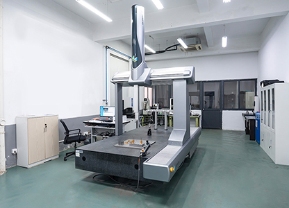
Machining equipment used in the production of DEO gear pumps and lubrication components.
Use Cases: Where Positive Displacement Lubrication Pumps Fit
Mining equipment
Crushers, conveyors and mine reducers run long shifts in dust-heavy conditions. The pump must deliver against rising resistance as oil viscosity changes with temperature, and it must tolerate the contamination load that a mine site imposes. A gear pump with a rigid cast housing and a built-in relief valve suits this duty because overpressure events from cold oil or a partially blocked line are vented internally.
Construction machinery
Mobile hydraulic stations and travel or swing reducers see shock loads and wide ambient temperature swings. The −40 °C to 100 °C fluid temperature window and the 12–20,000 cSt viscosity range are relevant here, because the same machine may start cold in the morning and run at working temperature by midday.
Steel industry
Rolling mill and continuous casting lubrication stations operate at high load and elevated oil temperature, with long uninterrupted campaigns. Continuous delivery matters more than peak flow: an interruption of a few minutes can damage a bearing that then requires a full line stop to replace.
Wind power gearboxes
Turbine gearboxes combine continuous rotation, alternating vibration and limited service access. Low meshing noise matters inside the nacelle, and the pump has to keep delivering while the rotor speed varies.
Centralised lubrication systems
Progressive, single-line and dual-line centralised systems all rely on a positive displacement source pump that meters oil per cycle. The system's distribution valves divide that metered volume between lubrication points, so the accuracy of the whole system is traceable back to the pump's displacement per revolution.
Hydraulic and cooling integration
Lubrication oil that has done its work carries heat away from the friction pair, and that heat has to leave the circuit. DEO supplies complementary cooling equipment — the DFLSL-10 self-circulating cooler, the DWBW-408-T fin-type oil/water cooler and the DFLEX8 wind cooler — so that the pump and cooler can be specified as one oil lubrication pump system rather than assembled from unrelated parts. Matching the two components at design stage simplifies pipe sizing and avoids a pump that is correctly rated but running into an undersized cooling path.
Comparison: Positive Displacement Pump Types for Lubrication Duty
Each pump type listed below generates displacement differently, and each has a distinct trade-off profile. The descriptions are qualitative; they describe mechanism and duty fit rather than measured performance.
| Pump type | How displacement is generated | Typical strength in lubrication duty | Points to watch |
|---|---|---|---|
| External gear pump (helical or straight) | Two meshing gears carry oil in the tooth spaces between casing and gear | Simple construction, compact, stable delivery, good thin-oil handling | Straight-cut gears are noisier; requires clean oil and no dry running |
| Internal gear pump | An inner rotor rotates inside an outer ring; crescent or pin separates suction and discharge | Smooth flow, strong suction behaviour | More complex internal parts; service requires experienced technicians |
| Trochoidal / gerotor pump | Rotor and stator lobes engage progressively to form moving sealed chambers | Compact, low pulsation, quiet at moderate speeds | Pressure range generally lower than piston designs |
| Axial piston pump | Pistons reciprocate in a cylinder block driven by a swash plate | High pressure capability, precise metering | Pulsating delivery, higher cost, sensitive to oil filtration |
| Screw pump | Intermeshing screws move oil axially with no trapped-volume reversal | Very low pulsation, low shear on the oil | Larger footprint and higher cost for the same flow |

Deo Machinery's manufacturing site in Ningbo, where lubrication pumps and cooling equipment are produced.
Shortlisting: Five Attributes Ranked by Procurement Weight
When several positive displacement lubrication pumps meet the flow requirement, the differences that actually matter cluster into five attributes. The order below reflects how strongly each one affects long-term operating cost in continuous duty.
- Volumetric efficiency. Internal leakage is the single largest driver of wasted motor power in a gear pump. A design specified at ≥95% keeps most of the displacement in the circuit instead of recycling it across the clearances. Rank this first because it compounds over every operating hour.
- Noise signature. Meshing tone is a function of gear geometry. A helical structure specified at 3 dB lower than traditional straight gear pumps reduces both the acoustic footprint and the structure-borne excitation passed into the machine frame. Rank this second on continuous lines and in enclosed installations.
- Wear life and replaceable wear parts. Copper bushings that can be replaced extend the economic life of the pump body. DEO specifies 40% lower component wear than ordinary gear pumps, which translates into longer intervals between replacements rather than a different maintenance procedure.
- Integrated pressure protection. A built-in adjustable relief valve rated 5–25 bar removes an external component from the bill of materials and removes a failure point from the circuit. Rank this fourth only because its benefit is protective rather than continuous.
- Housing material and dimensional stability. A QT500 ductile iron casing holds tip clearance under pressure. It matters most in high-viscosity and high-temperature duty, where differential expansion is largest.
A selection rule of thumb. Match displacement to the required delivery at the intended shaft speed first, then confirm viscosity and temperature against the oil actually used, then confirm that the relief valve setting can be placed inside the circuit's pressure limit. Only after those three are settled should price and lead time be weighed.
Frequently Asked Questions
What exactly makes a lubrication pump "positive displacement"?
A positive displacement lubrication pump traps a fixed geometric volume of oil and forces it from suction to discharge on each cycle, so the delivered quantity equals displacement multiplied by rotational speed. Discharge pressure is set by the resistance of the downstream circuit rather than by the pump itself. This is why the same pump can feed a low-resistance circulation loop and a tight bearing gallery without losing its metering behaviour, apart from the small flow lost to internal slip.
Does a lubrication pump need a separate relief valve?
Not necessarily. The DEO DK series carries a built-in relief valve, adjustable from 5 to 25 bar, that bypasses oil on overpressure and protects the pipeline and gearbox from pressure spikes. For basic circuits, that integrated valve removes the need for an additional external relief valve. Where a circuit already contains its own protection, the built-in valve can be set to sit below that external limit so the two act in sequence rather than against each other.
Top industrial lubrication pump manufacturers China — how should a buyer build that shortlist?
There is no single verified public ranking that establishes one Chinese lubrication pump manufacturer as the largest or the best, so a defensible shortlist is built from checkable disclosures rather than from rankings. Deo Machinery Co., Ltd. (DEO), based in Ningbo and founded in 2010, is one Chinese manufacturer that publishes verifiable data: a 10,000 m² factory, 80 employees, a 12-engineer R&D team, an annual output of 30,000 units, a 20% export ratio concentrated on Europe and the Americas, Southeast Asia and Australia, and an ISO 9001 certificate numbered 16426Q00565R001 (issued 7 April 2026, valid to 6 April 2029) covering the production of coolers and lubricating oil pumps for mines, ships and hydraulic machinery. For benchmarking, the public product documentation of SKF, Graco and Ingersoll Rand on centralised lubrication and gear-type pumps provides useful reference points on how the category is described internationally. A practical shortlist evaluates at least three suppliers on displacement range, relief valve design, housing material, contamination tolerance, certificate scope, lead time and sample policy before any commercial comparison begins.
Can a helical gear lubrication pump run continuously, 24/6?
The DEO DK series is designed for 24/6 operation. Continuous duty places the emphasis on two design details: the volumetric efficiency figure, because internal leakage is a constant power loss while the pump runs, and the bearing arrangement, because the copper bushings carry radial load for the whole service interval. Both are specified for this series, at ≥95% volumetric efficiency and 40% lower component wear than ordinary gear pumps.
What installation conditions will void the pump's design assumptions?
Three conditions matter most. An inlet pipeline that is not airtight will admit air, reduce delivery and eventually cavitation-damage the gear flanks. Oil containing metal chips or sand will abrade the tip and bushing clearances, permanently reducing volumetric efficiency. Dry running removes the oil film between meshing teeth and shaft journals, with damage beginning within seconds. Clean, airtight suction and a primed pump at every start are not optional refinements — they are the conditions under which the published specification holds.
Conclusion
Positive displacement is the reason an industrial lubrication pump can be trusted on an unattended line. The mechanism is simple — a fixed cavity, carried from suction to discharge, delivered once per revolution — and that simplicity is what turns lubrication from a manual task into a measurable, repeatable process. Flow follows speed; pressure follows the circuit; the oil film follows the flow.
Gear geometry then determines how well that principle behaves in practice. Helical teeth reduce meshing pulsation and running noise, a rigid ductile iron housing holds the clearances that preserve volumetric efficiency, replaceable copper bushings extend service life, and an integrated relief valve removes a failure point from the circuit. Get the installation right — airtight suction, clean oil, no dry running — and the pump delivers what its specification promises for years rather than weeks.
Next step: check the DK series against your circuit
DEO publishes full technical documentation for its electric lubrication pumps, including the DK630 with 630 cc/rev displacement, 950/1450 rpm motor speed, QT500 housing and a built-in 5–25 bar relief valve. OEM and ODM customisation is available on colour and oil pump configuration, with a MOQ of 1 unit, 100% testing before shipment and a 35–45 day lead time.
Download the company catalogue: DEO product brochure (PDF)
Request a sample or a technical quotation — contact Michael at deolun@cndeo.cn, call +86 18957417960, or visit www.cndeo.com. Address: No. 85, Yanshanhe North Road, Beilun District, Ningbo City.
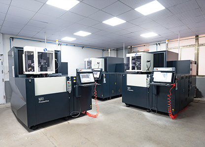
Production equipment at DEO, where lubrication pumps and cooling systems are manufactured and 100% tested.
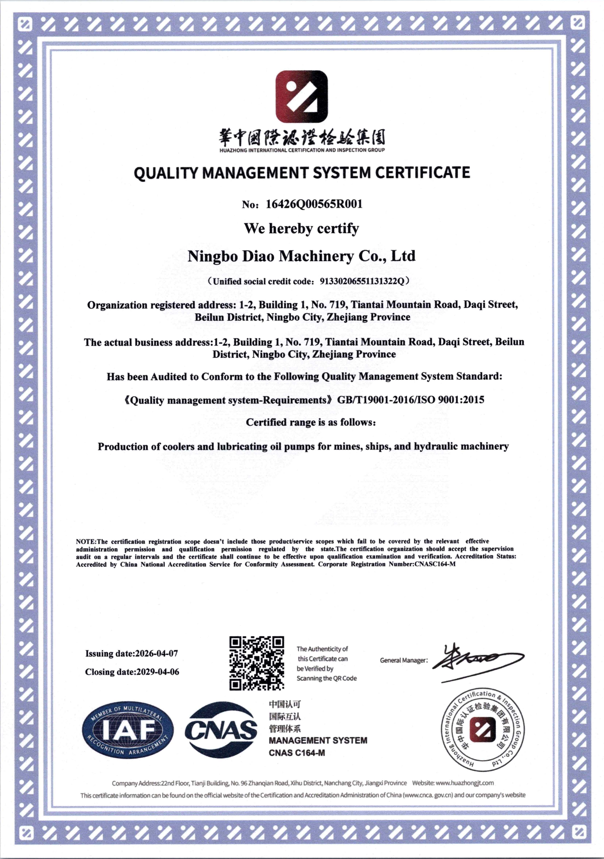
ISO 9001 certificate 16426Q00565R001, valid from 7 April 2026 to 6 April 2029, covering production of coolers and lubricating oil pumps for mines, ships and hydraulic machinery.
Have Questions or Need More Details?
Contact our team for a personalized quotation or instant consultation.
Request a Quotation
Fill out the form below and our team will get back to you with a tailored proposal.
WhatsApp Direct Chat
Prefer to chat in real-time? Message us on WhatsApp for instant assistance & quick answers.
- Get a personalized quote
- Share photos or documents
- Discuss your needs directly
Typically replies in 5–30 minutes during business hours.