Tube Laser Cutting Machine Positioning Errors: How to Solve Slippage and Sagging
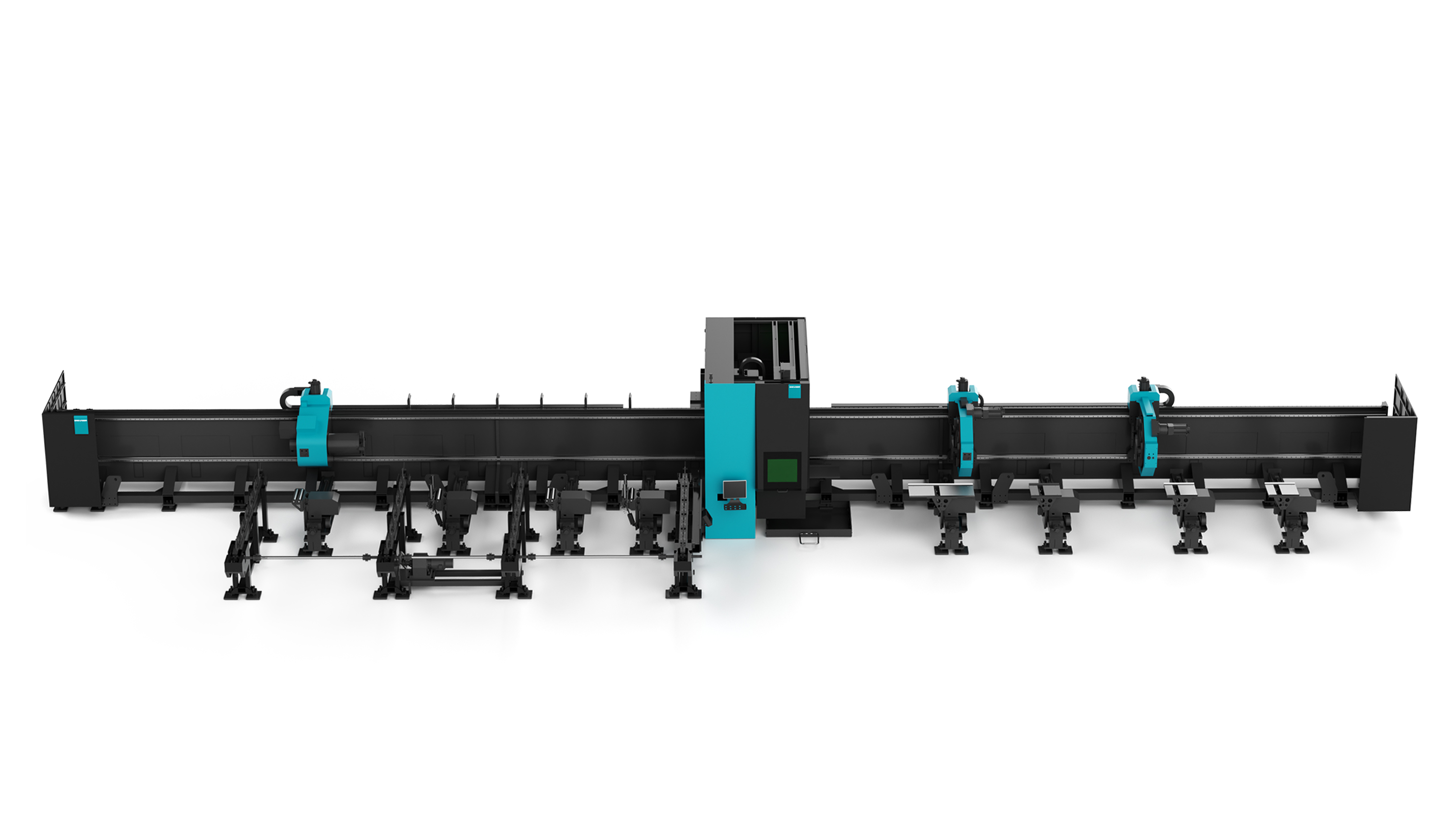
DNE LASER D-Tube 520 — a fiber tube laser cutting machine configured with 3 or 4 chucks and a theoretical maximum chuck load of 1,500 kg.
Positioning errors on a tube laser cutting machine are usually mechanical, not programmatic. When a heavy or long tube slips inside the chuck, sags between supports, or begins to oscillate during rapid axis travel, the cutting head is no longer where the controller believes it is. The cut drifts, the hole pattern shifts, weld fit-up fails, and material is scrapped. The DNE LASER D-Tube series addresses that failure class at its source — clamping load, tube support and multi-chuck coordination — with a specified X/Y positioning accuracy of ±0.05 mm/m, repeated positioning accuracy of ±0.03 mm/m, and a theoretical maximum chuck load of up to 1,500 kg on the D-Tube 520.
Problem Definition: Slippage, Sagging and Oscillation Are Three Different Failures
A tube that moves during cutting destroys accuracy in a way that is easy to misread. Three mechanically distinct events are usually described on the shop floor with the same sentence — 'the machine is cutting out of position'.
Slippage is relative motion between the tube and the chuck. The tube rotates slightly inside the jaws, or creeps along its own axis, so the programmed path no longer matches the physical tube. The symptom is progressive rather than sudden: the first parts measure correctly, then cut-off length starts to drift and hole patterns land off-centre. On a heavy round tube, a small angular slip at the chuck becomes a large positional error at the far end of the bar.
Sagging is gravity deflection across an unsupported span. A long tube held only near its ends bows downward in the middle, the cutting zone moves away from the ideal focus position, and the machine cuts geometry along a curved axis instead of a straight one. Thin-wall tube adds a second failure mode, because the wall itself can deform under clamping pressure before gravity becomes the limiting factor.
Oscillation, sometimes called whip, is vibration excited by rapid axis travel. Heavier tubes store more kinetic energy and longer tubes have lower natural frequencies, so a machine that cuts short, light sections cleanly can still show vibration marks and inconsistent kerf on a full-length heavy bar.
Each failure has a different root cause, and therefore a different remedy. Treating all three as a servo tuning problem is the fastest way to waste a service visit.
| Failure mode | Typical symptom | Mechanical root cause | Countermeasure available on the D-Tube platform |
|---|---|---|---|
| Chuck slippage | Cut-off length drifts during a shift; hole pattern or seam lands off-position | Clamping force below what tube weight and surface condition require; worn or contaminated jaws | 2 to 4 chuck configurations with theoretical maximum chuck loads from 100 kg (D-Tube F 120) to 1,500 kg (D-Tube 520); stable clamping for heavy-duty tubes is a stated requirement of the tube processing scenario |
| Mid-span sagging | Taper or ovality on the cut face; focus drift on long tubes | Long unsupported span deflecting under the tube's own weight | Follow-up support and centering devices for assisted loading; optional fully or semi-automatic loading systems |
| Oscillation / whip | Inconsistent kerf, vibration marks, occasional alarms during fast moves | Tube mass and length interacting with rapid axis acceleration | Multi-chuck synchronized operation, intelligent CNC system control and real-time adjustable process parameters |
| Remnant loss | The last section of every bar is scrapped | Tube cannot be held once the remaining length is shorter than a safe clamping span | Zero or short remnant cutting capability; optional automatic unloading and remnant handling systems |
In practice these failures overlap. A tube at the upper end of a machine's load range can sag between supports while oscillating under acceleration, and still leave a remnant that the shop would rather cut than scrap.
Industry Background: Tube Stability Is Becoming a Harder Mechanical Problem
Tube and profile cutting sits inside a market that is growing quickly and moving toward heavier work. Fortune Business Insights projects the global laser cutting machines market to grow from USD 7.44 billion in 2026 to USD 18.43 billion by 2034, a CAGR of 12%. China's laser equipment market accounted for 56.6% of global laser equipment revenue in 2024, with high-power laser localization exceeding 70% (IT Home / CCTV Finance).
The technology mix has already shifted. Fiber lasers hold more than 55% of the industrial laser systems market, displacing CO2 sources (SNS Insider), and demand for ultra-high-power laser heads of 10 kW and above grew by 75% between 2023 and 2024, driven by thick-plate cutting requirements in heavy industry (Customcy).
Tube processing follows the same curve. Tube and profile work appears in automotive manufacturing, machinery and plant engineering, construction machinery, agricultural machinery, transport systems manufacturing, telecommunications equipment manufacturing, construction, kitchenware manufacturing and aerospace manufacturing. The operating conditions are demanding: industrial plant environments, high-dust metal processing workshops and 24/7 continuous operation.
As tube size and weight rise, the load the chuck must hold rises with them. The D-Tube 520, for example, is specified for round tube from Φ50 to Φ510 and square tube from □50×50 to □510×510, with a theoretical maximum chuck load of 1,500 kg. That is a class of tube where clamping and support design — not cutting speed — determines whether the part is in tolerance.
How the DNE LASER D-Tube Series Addresses Slippage and Sagging
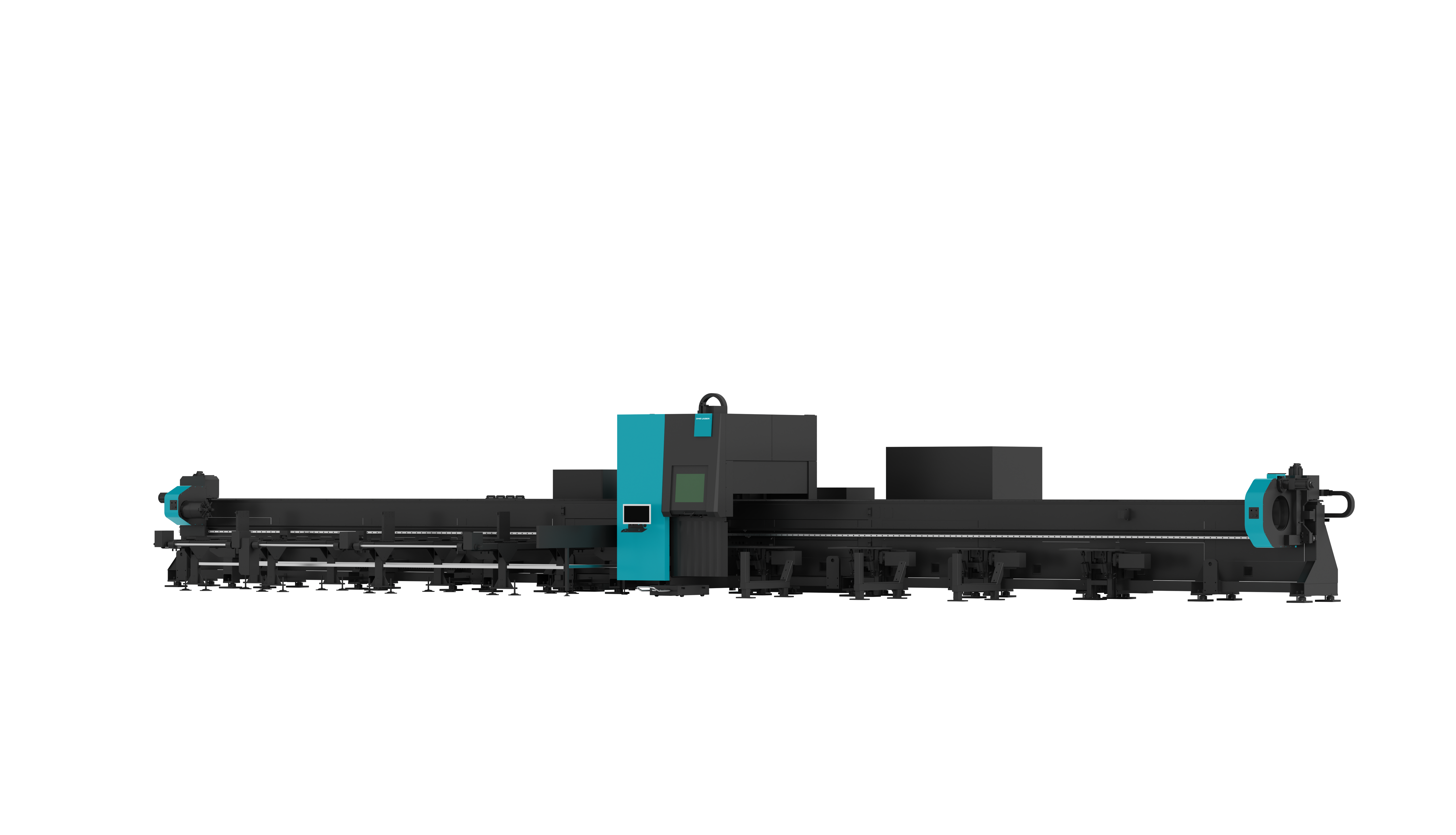
D-Tube 360: 2, 3 or 4 chucks, round tube Φ40–Φ350, square tube □40×40–□350×350, theoretical maximum chuck load 1,200 kg.
DNE LASER (Guangdong) Co., Ltd., which trades under the brand DNE LASER, is a laser equipment manufacturer headquartered in Shenzhen with its production base in Nanhai, Foshan, and a wholly owned subsidiary of the Swiss Bystronic Group. Its range covers laser cutting machines, tube laser cutting machines, press brakes, automation devices, laser welding machines and software. The tube platform relevant to positioning stability is the D-Tube series, offered in D-Tube F, D-Tube 240, D-Tube 360 and D-Tube 520 configurations.
Six configuration decisions in that series map directly onto the failure modes described above.
1. Chuck Count and Clamping Load Matched to Tube Weight
The first defence against slippage is holding capacity. The D-Tube F uses two chucks across its three sizes, with a theoretical maximum chuck load of 100 kg for the Φ8–Φ120 model, 300 kg for the Φ12–Φ240 model and 1,000 kg for the Φ40–Φ350 model. The D-Tube 240 offers 2 or 3 chucks with a 300 kg theoretical maximum chuck load. The D-Tube 360 offers 2, 3 or 4 chucks at 1,200 kg. The D-Tube 520 offers 3 or 4 chucks at 1,500 kg.
Chuck quantity matters because clamping load is distributed rather than concentrated. A 12.5 m bar held by three or four chucks is gripped at more points, and the span each chuck has to stabilise is shorter than on a two-chuck arrangement. Chuck type and quantity are also listed as configurable options, so the clamping arrangement can be matched to the tube family a shop actually runs rather than to an average.
2. Holding Clamping Force Constant Across the Shift
Slippage that appears gradually is almost always a clamping-force problem rather than a motion problem. Clamping force has to remain constant through the cutting cycle; any reduction lets the tube creep, and creep is cumulative along the bar. Dust and chips are a common cause of progressive loss of clamping force, which is why the tube processing scenario explicitly lists high-dust metal processing workshops as a working condition and stable clamping for heavy-duty tubes as a special requirement.
When evaluating any tube laser cutting machine, verify these four points rather than assuming them:
- Whether the clamping mechanism is protected from chips and dust ingress over a full production shift
- Whether clamping force is monitored or can be verified at the start of each shift
- Whether jaw condition is included in scheduled maintenance
- Whether the clamping arrangement on offer is rated for the heaviest tube in your production mix, not the average
3. Follow-Up Support and Centering Devices Reduce Unsupported Span
Sagging is a geometry problem, and the geometry fix is support. The D-Tube configurations are supplied with follow-up support and centering devices for assisted loading, together with optional fully or semi-automatic loading systems. A follow-up support travels with the tube as it is fed, shortening the unsupported span and keeping the tube axis aligned with the chuck axis, while the centering device reduces the eccentricity introduced when an out-of-round or non-standard profile enters the chuck.
This is the difference between a machine that can physically accept a heavy tube and a machine that can hold that tube in position while it is cut.
4. Multi-Chuck Synchronized Operation and Zero or Short Remnant Cutting
Position stability through the whole bar — including the end of the bar — depends on chuck coordination. The tube processing operation mode is multi-chuck synchronized operation under intelligent CNC system control, with real-time adjustable process parameters. Synchronised chucks let the tube be handed between clamping points rather than released, which suppresses vibration during fast positioning moves and keeps the cutting zone supported.
The same coordination enables zero or short remnant cutting capability, and the platform can also be specified with automatic unloading and remnant handling systems. Instead of scrapping the last section of every bar because it is too short to hold safely, the remnant can be clamped and cut, which changes material yield on high-value or high-volume tube work.
5. Positioning Accuracy That Can Be Measured
Stability claims are only useful if they can be checked against a number. Across the D-Tube F, D-Tube 240, D-Tube 360 and D-Tube 520, the specified X/Y-axis positioning accuracy is ±0.05 mm/m and the X/Y-axis repeated positioning accuracy is ±0.03 mm/m. Repeated positioning accuracy is the practical metric for diagnosing slippage, because a mechanical holding problem shows up as degradation in repeatability rather than as a single bad part.
Bevel cutting is available as an optional function on the series. Loading length options range up to 12.5 m, with unloading length options from 2 m up to 12.2 m depending on model and configuration.
6. Uptime: Remote Support When a Fault Does Occur
Even a correctly specified machine eventually needs attention, and unplanned downtime is where stability problems become expensive. The tube processing support package covers remote technical support and troubleshooting, on-site installation, commissioning and operator training, scheduled maintenance services, core component warranty, and lifetime technical upgrades and process optimisation support.
The practical question for a buyer is not whether a machine can run for a year without service, but how quickly a chuck or axis fault is diagnosed. Remote troubleshooting as a first line of response shortens the interval between an operator noticing position drift and a technician confirming the cause.
Step-by-Step: A Practical Sequence for Eliminating Tube Positioning Errors
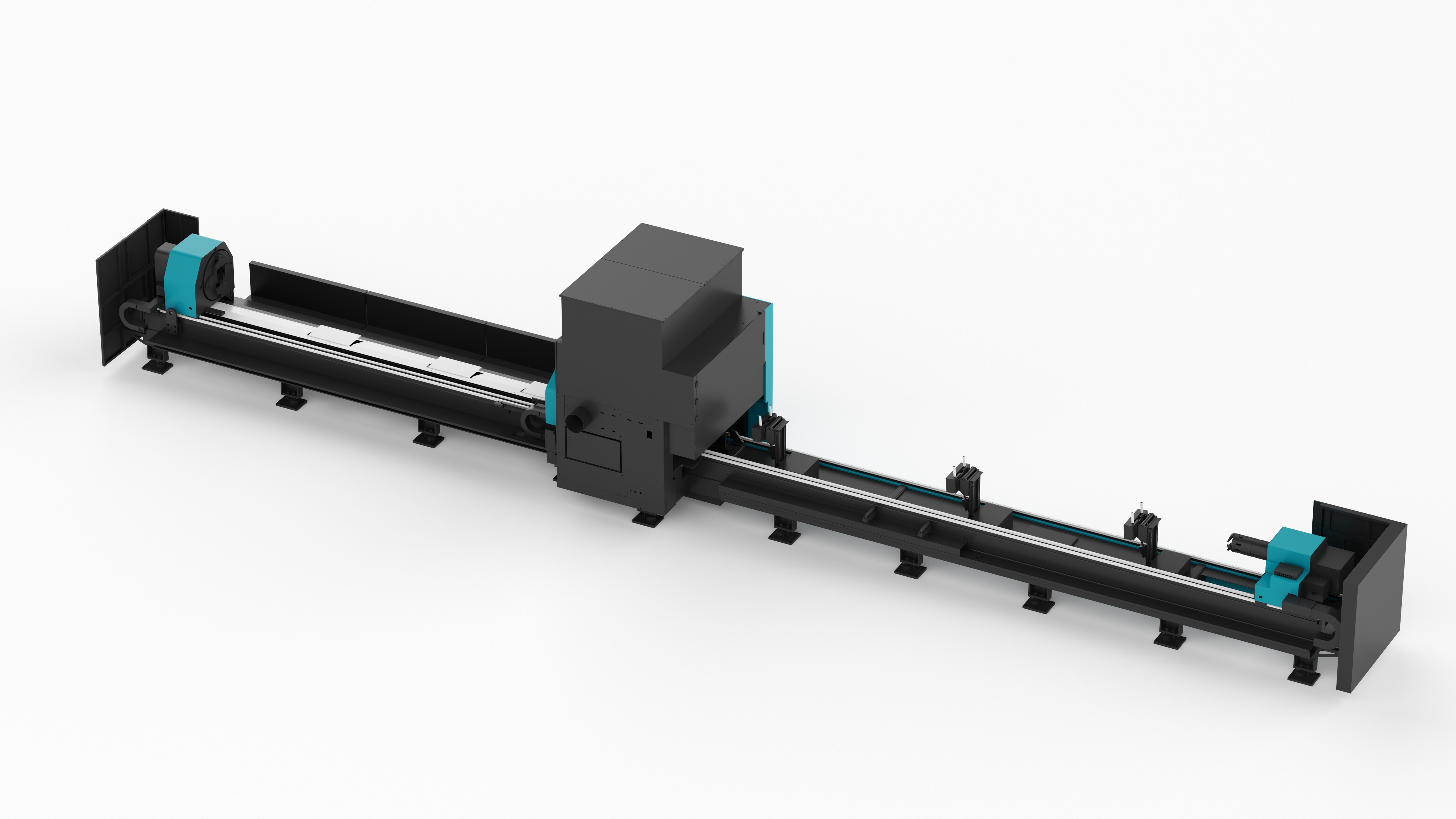
D-Tube 240: 300 kg theoretical maximum chuck load, round tube Φ15–Φ230, square tube □15×15–□230×230.
- Classify the error before touching parameters. Record whether deviation is in cut length, hole position, cut-face taper or surface finish. Length and angular drift point to slippage; taper and focus drift point to sagging; inconsistent kerf points to oscillation. Cutting parameters cannot correct a clamping fault.
- Match chuck count and clamping load to the heaviest tube in the mix. Use the theoretical maximum chuck load as a hard ceiling, not a target: 100 kg and 300 kg and 1,000 kg across the D-Tube F sizes, 300 kg for the D-Tube 240, 1,200 kg for the D-Tube 360 and 1,500 kg for the D-Tube 520.
- Verify clamping force at the start of a shift. Compare it with the value recorded when the machine was commissioned. A downward trend across weeks is the signature of dust ingress or jaw wear rather than of a control problem.
- Set support and centering positions against tube length, not against habit. Follow-up support and centering devices for assisted loading exist to shorten the unsupported span; the correct position changes when bar length or wall thickness changes.
- Review motion parameters against tube mass. Multi-chuck synchronized operation and real-time adjustable process parameters allow acceleration and speed to be matched to what the tube can tolerate. A parameter set tuned on thin-wall tube will not stabilise a heavy bar.
- Plan the remnant before the job starts. Zero or short remnant cutting capability only pays off if the nesting and the unloading strategy are configured for it. On the platform this can include automatic unloading and remnant handling systems.
- Lock in accuracy verification. Use the ±0.05 mm/m positioning accuracy and ±0.03 mm/m repeated positioning accuracy specifications as the reference line, and check repeatability after any maintenance that touches the chucks or the support devices.
Where This Matters: Verified Application Experience
The stability requirements described above are not theoretical. In a Vietnamese automotive parts manufacturer, nine units were installed for automobile and component manufacturing, including the D-Soar fiber laser cutting machine and the D-Tube 240 tube laser cutting machine. After one year of use, the operation reported improved production efficiency of 15%, with faster cutting speed, low maintenance and long lifespan cited as the practical highlights.
A Mexican industrial automation manufacturer took a different route. Three units, including the D-Giant laser cutting machine and the D-Tube 360 tube laser cutting machine, were used for three years in the production of intelligent equipment and precision structural parts, after which three additional sets were purchased. That project also reported a 15% improvement in production efficiency.

DNE LASER's production base in Nanhai, Foshan covers more than 60,000 m² and supports a workforce of over 600 people.
The company behind these machines operates a production base of more than 60,000 m² with over 600 employees, an annual output of 2,000+ units, a 38-engineer R&D team and an export ratio of 45%. It is a National High-Tech Enterprise, holds Smart Manufacturing Capability Maturity Level 2 Certification, has been approved to establish the Guangdong Provincial Engineering Research Center for Ultra-High-Speed Fiber Laser Cutting Machines, and is recognised among the Shenzhen Top 500 Enterprises.
D-Tube Series Comparison for Tube Stability Requirements
The table below compares the verified specifications that determine whether a given tube can be held and positioned reliably. Use it to check the tube you actually cut against the machine class, rather than against a general impression of machine size.
| Model | Chuck options | Round tube range | Square tube range | Theoretical max. chuck load | Positioning / repeated accuracy | Loading / unloading length |
|---|---|---|---|---|---|---|
| D-Tube F 120 | 2 | Φ8–Φ120 mm | □8×8–□120×120 mm | 100 kg | ±0.05 mm/m / ±0.03 mm/m | 6.5 m / 2 m |
| D-Tube F 240 | 2 | Φ12–Φ240 mm | □12×12–□240×240 mm | 300 kg | ±0.05 mm/m / ±0.03 mm/m | 6.5 m / 2 m |
| D-Tube F 360 | 2 | Φ40–Φ350 mm | □40×40–□350×350 mm | 1,000 kg | ±0.05 mm/m / ±0.03 mm/m | 6.5 m / 2 m |
| D-Tube 240 | 2 or 3 | Φ15–Φ230 mm | □15×15–□230×230 mm | 300 kg | ±0.05 mm/m / ±0.03 mm/m | 6.5–12.5 m / 2–12.2 m |
| D-Tube 360 | 2, 3 or 4 | Φ40–Φ350 mm | □40×40–□350×350 mm | 1,200 kg | ±0.05 mm/m / ±0.03 mm/m | 6.5–12.5 m / 2–12.2 m |
| D-Tube 520 | 3 or 4 | Φ50–Φ510 mm | □50×50–□510×510 mm | 1,500 kg | ±0.05 mm/m / ±0.03 mm/m | 12.5 m / 6.5–12.2 m |
Bevel cutting function is optional across the D-Tube series. Specifications above are as published for the D-Tube F, D-Tube 240, D-Tube 360 and D-Tube 520.
FAQ: Tube Laser Cutting Machine Positioning and Stability
Does a tube laser cutting machine for heavy tubes have to meet specific safety standards?
Yes. Compliance with CE safety standards is listed as a special requirement for tube processing applications, and laser processing machines are subject to ISO 11553-1 for general safety requirements and IEC 60825-1 for equipment classification in international trade and CE marking. On the manufacturing side, tube laser cutting equipment is tested in line with industrial tube cutting equipment safety requirements, including compliance verification of core component brands.
Can the D-Tube series hold a long, heavy tube without slippage or sagging?
Holding capacity is specified per model. Theoretical maximum chuck load is 300 kg on the D-Tube 240, 1,200 kg on the D-Tube 360 and 1,500 kg on the D-Tube 520, with the D-Tube F covering 100 kg, 300 kg and 1,000 kg across its three sizes. Chuck counts range from 2 to 4, loading length reaches 12.5 m, and the series is supplied with follow-up support and centering devices for assisted loading plus multi-chuck synchronized operation, with X/Y positioning accuracy of ±0.05 mm/m and repeated positioning accuracy of ±0.03 mm/m.
What drives the cost of a tube laser cutting machine configuration?
Cost is driven by configuration rather than by a single headline number. Configurable elements on the tube platform include chuck type and quantity, laser power, loading and unloading system configuration, bevel cutting function, and cutting range and tube specification compatibility. A shop cutting thin-wall tube across short bars and a shop cutting Φ510 heavy sections need materially different machines, so a configuration should be built against tube diameter, wall thickness, bar length and target throughput. That is also why published factory specifications should be used as the comparison basis rather than a machine size label.
How is a tube laser cutting machine validated before it ships?
Factory validation on the tube platform covers full-process performance testing, chuck and cutting accuracy calibration, a continuous operation trial run of the complete machine, and compliance verification of core component brands, with testing in line with industrial tube cutting equipment safety requirements. After delivery, the support scope includes on-site installation, commissioning and operator training, plus scheduled maintenance services, core component warranty, and lifetime technical upgrades and process optimisation support. Minimum order quantity for the platform is one unit, which allows a single machine to be validated in a real production environment before wider roll-out.
How long does delivery take, and what support follows installation?
Lead time is customised based on actual order volume and project requirements, so it is quoted against the specific configuration rather than as a fixed figure. Post-installation support covers remote technical support and troubleshooting, on-site installation, commissioning and operator training, scheduled maintenance services, core component warranty, and lifetime technical upgrades and process optimisation support — the combination that matters when a positioning issue has to be diagnosed quickly rather than scheduled weeks ahead.
Conclusion
Slippage, sagging and oscillation are mechanical failures, and they are solved mechanically: with clamping capacity that matches the tube weight, clamping force that stays constant through the shift, support that shortens the unsupported span, chuck coordination that holds the tube through the whole bar, and positioning accuracy that can be verified against a specification. On the DNE LASER D-Tube series, those elements are visible in specified values — 2 to 4 chucks, theoretical maximum chuck load from 100 kg to 1,500 kg, loading length up to 12.5 m, and ±0.05 mm/m positioning accuracy with ±0.03 mm/m repeated positioning accuracy — rather than in claims alone.
The practical starting point is your own tube list. Diameter, wall thickness, bar length and required cut tolerance determine which of those values is the binding constraint, and which configuration actually keeps the tube where the program says it is.
Next Step: Match a D-Tube Configuration to Your Tube Mix
If your current machine is losing position on heavy rounds, sagging on long bars, or scrapping the remnant of every tube, send the DNE LASER tube cutting team your tube diameters, wall thicknesses, bar lengths and target tolerance. We will map them to a D-Tube configuration with the matching chuck count, clamping load, support arrangement, loading system and bevel option, and confirm the accuracy specification the machine has to hold.
Company and product overview (PDF): Introduction of DNE Laser V1.0 (2026)
Email: eileen.yan@dne.global | WhatsApp / Tel: +86 136-7014-5102 | Website: www.dne.global
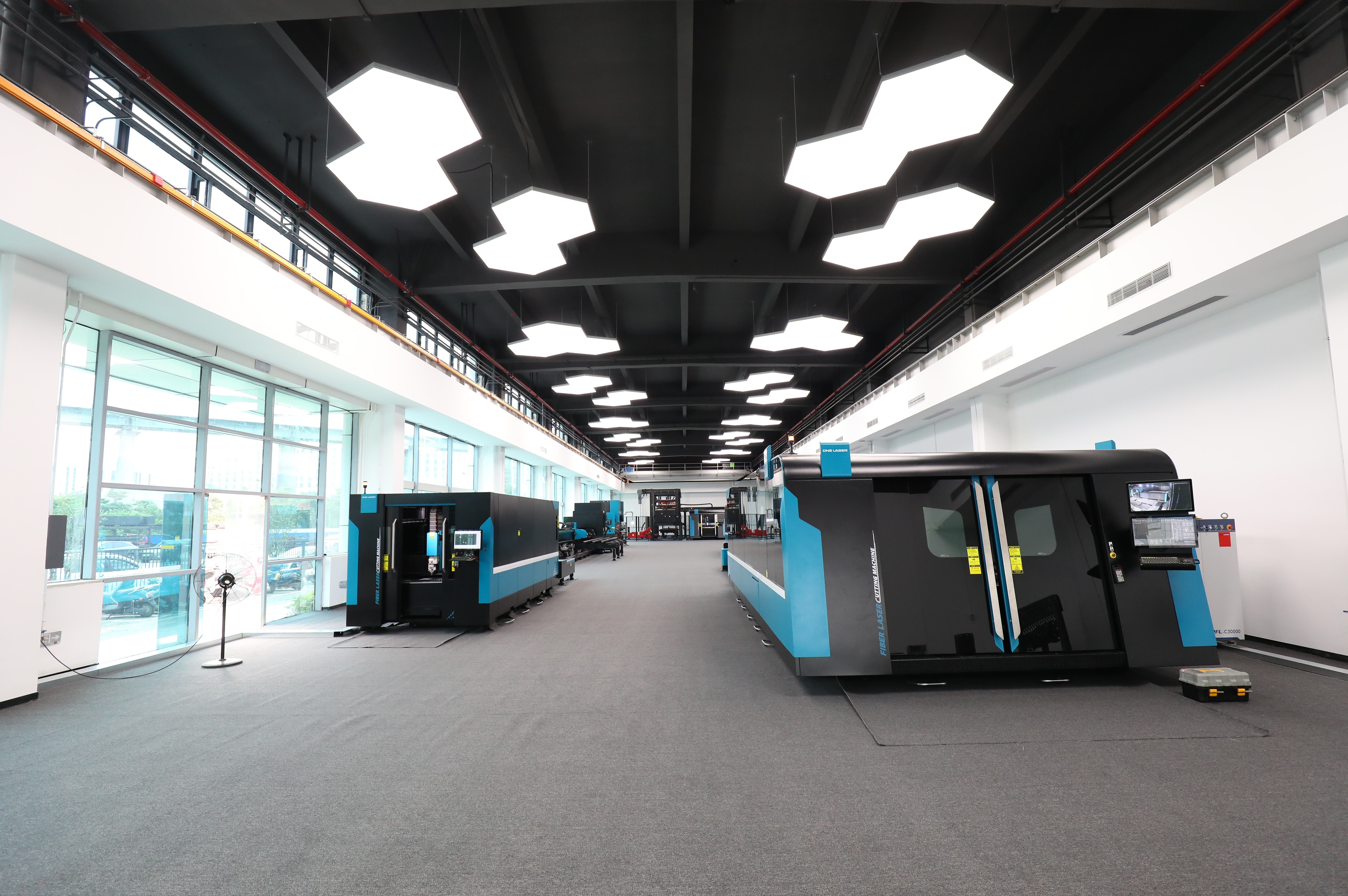
DNE LASER demo centre — where tube specifications are matched to a D-Tube configuration.