
CNC Machining Center Anatomy: Fixed Column, Marble Base, ISO 50 Spindle, and 24-Pocket ATC
The short answer: a CNC machining center is built from six interacting blocks — a fixed column and bed structure, the materials inside that structure, a work table carried on three linear axes, a spindle defined by its taper, an automatic tool changer fed by a tool magazine, and a CNC control system. Each block sets a boundary on the part sizes, materials and cycle times the machine can handle. The sections below define every block and attach real numbers from a published machine: the EV-855A vertical machining center from EUMASEIKI.
EUMASEIKI is the brand of Wenzhou Euma Machinery Co., Ltd., a machine tool manufacturer founded in 2023 that runs an 8,000 m² production base in Ningbo, China, and specializes in customized CNC machining centers. Every figure in this article comes from the EV-855A published configuration or from the company’s certification records. One clarification before the dissection begins: spindle taper is a per-model specification, and the reference machine here carries an ISO 40 type taper. The larger ISO 50 category is defined in the spindle section so the two are easy to tell apart on a quotation.
Why Machine Anatomy Is a Buying Problem, Not Just an Engineering One
Most first-time buyers meet a CNC machining center through a quotation rather than a textbook. The quotation lists table size, spindle speed, magazine capacity and control model; the photographs show machines that look almost identical. What the documents rarely explain is which part is responsible for which outcome — and that gap is where specification mistakes begin.
Functionally, a CNC machining center delivers five capabilities in one enclosure: it holds a workpiece on a table, rotates a cutting tool in a spindle, exchanges that tool automatically from a magazine, moves tool and workpiece relative to each other along controlled linear axes, and executes the whole sequence from a stored program in a CNC control. The column, bed, taper and magazine are not extras bolted onto that definition — they are the physical decisions that determine how well each of the five functions performs.
Three failure patterns repeat whenever anatomy is ignored:
- Envelope mismatch. A buyer selects on table size alone, then discovers that Z-axis travel and the spindle-nose-to-table distance cannot fit the fixture plus the tool stack. The work is machinable in theory and not in practice.
- Duty mismatch. Motor power is compared without separating continuous from intermittent ratings, so a machine rated for short, heavy cuts is expected to run a continuous load it was never specified for.
- Tooling mismatch. Magazine capacity is read as a simple number, ignoring the maximum tool diameter, length and weight a pocket can carry — which is what actually limits a multi-operation cycle.
Each of these is decidable before purchase, and each becomes expensive afterwards. The rest of this article follows the order in which the machine is assembled — structure, table, spindle, tool changer, control — and then shows how the blocks sequence during a single production cycle.
Industry Background: Why These Building Blocks Are Being Re-Examined
Anatomy matters more now than it did a decade ago, because the market around it has both grown and fragmented. The global market for CNC machining and turning centers was estimated at USD 27.64 billion in 2024 (Grand View Research). That is not the only figure in circulation: Mordor Intelligence places the 2025 machining center market at USD 22.41 billion. The gap is largely a scope question — whether turning centers are counted alongside machining centers — and it is a useful reminder to read any market number with its definition attached.
Within that market, the vertical architecture is the workhorse. Vertical machining centers took 52.3% of the 4-axis CNC machining center market in 2025 (Dataintelo). The reason is structural: a fixed-column vertical layout is simpler to keep rigid, easier to load from the front and easier to fit with standard workholding — which is why the block-by-block anatomy below uses a VMC as its reference machine.
Supply has shifted as well. China’s machine tool exports reached USD 8.56 billion in the first five months of 2024, up 1.8% year on year (China Customs data reported by ICE Pechino). The practical consequence for buyers is a much longer supplier list and much less time to screen it — which pushes the selection decision back onto verifiable anatomy instead of brand recognition.
Multi-axis machines are growing alongside the vertical mainstream: the 5-axis CNC machining center market was valued at approximately USD 7.35 billion in 2024, with a projected CAGR of 4.6% to 2035 (WiseGuyReports), and aerospace was the largest application segment with a 28.7% revenue share in 2025 (Dataintelo). The point for anyone learning the anatomy is that adding rotary axes does not replace the fundamentals: a 5-axis machine still stands on the same base, column, spindle and tool magazine decisions, with two more controlled axes layered on top.
Measurement deserves the same attention. ISO 230-2:2014 remains the current international framework for determining accuracy and repeatability of positioning for numerically controlled axes (ISO). Catalogue accuracy figures only mean something when that basis is stated — the same machine inspected under different conditions can produce different-looking numbers.
Finally, the ranking question buyers ask most often: DMG Mori, Yamazaki Mazak and Haas Automation are the manufacturers most frequently identified as the global top three by market presence and technology (AMSL / Mechrank). For a purchase decision, the useful part is not the list but the criteria behind it — technology, presence and support depth — all of which show up directly in the anatomy that follows.
The Building Blocks of a CNC Machining Center, One by One
1. The fixed column and the structural frame
The column is the vertical structural member that carries the spindle head. In a fixed-column vertical machining center — the most common C-frame architecture and the category the EV-855A belongs to — the column itself does not translate. The spindle head travels vertically along it, while X and Y positioning is carried by the table and saddle on the bed.
Fixing the column removes one large moving mass from the accuracy chain: the only remaining interface to control in Z is the guideway pair between head and column. That is a design trade rather than a universal advantage — a fixed column concentrates stiffness and simplifies geometry, while machines that move the column gain travel in exchange for a more complex structural loop.
For a buyer, the fixed column translates into two questions worth asking in writing: what the column and bed are made of, and whether the structure was analysed and stress-relieved before machining. Those two answers separate machines that hold geometry for years from machines that settle.
2. Base and column materials: marble mineral casting, cast iron, special steel
The EV-855A is constructed from cast iron, special steel, marble and precision electronic components. Material choice is not a decorative detail — the base and column establish the geometric reference for every axis, so anything that moves inside them later (residual stress, thermal growth, weak damping) reappears as drift, chatter and inconsistent surface finish.
EUMASEIKI’s structural approach is documented: machine beds adopt mineral castings, whose structures are optimized through finite element analysis. All castings undergo full annealing treatment to eliminate internal stress, and the spindle guideways are subject to high-frequency heat treatment. Read as anatomy, that sequence means: the casting is shaped for load paths, released from internal stress before it is finish-machined, and the surfaces that carry the spindle head are hardened against wear.
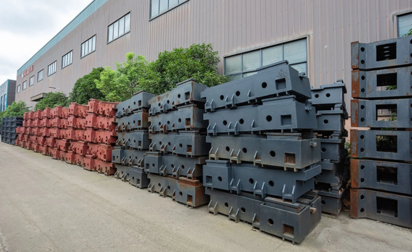
The decision value is straightforward. A claim of “marble base” or “mineral casting” says little by itself; the questions that matter are whether the casting was analysis-optimized, whether it was fully annealed, and how the spindle guideways were hardened. Those three answers are what a buyer can actually verify during a factory visit.
3. The work table and the three linear axes
On the EV-855A the work table measures 1000 × 550 mm, carries a maximum load of 650 kg, and uses T-slots of 18 × 90 × 5 mm (slot width × pitch × number). Axis travels are 810 mm in X, 550 mm in Y and 560 mm in Z. The spindle nose sits between 130 and 690 mm above the worktable, and the spindle centre is 595 mm from the column.
Those numbers answer different questions. X and Y travel define the workpiece footprint that can be machined in one setup. The spindle-nose-to-table range defines the tallest workpiece-plus-fixture-plus-tool stack: 130 mm is the minimum stand-off, 690 mm the maximum. The 650 kg table load caps fixture and workpiece mass together, and the T-slot pitch determines which clamping kits bolt straight down.
Underneath, the motion system is specified as ball screws of φ40/16 mm and linear guideways of 35/45/45 mm (X/Y/Z), with rapid feed rates of 48/48/32 m/min and a cutting feed rate of up to 20,000 mm/min. These are the load-carrying and speed-defining elements under the worktable: larger guideway and screw cross-sections generally indicate a table designed to be pushed harder.
Positioning accuracy on this model is 0.008 mm and repeat positioning accuracy is 0.005 mm. Values like these are only comparable when the measurement basis is the same on both sides of the comparison, which is exactly the role of the ISO 230-2:2014 framework for determining positioning accuracy and repeatability on numerically controlled axes.
4. The spindle: taper, speed and drive
The spindle is the rotating assembly that clamps the tool holder and transmits cutting force into the workpiece; the taper is the interface between spindle and tool holder, and it is the single term that causes the most confusion in first-time comparisons.
ISO 40 and ISO 50 are standard spindle taper sizes within the widely used steep-taper family. ISO 50 is the larger of the two: it accepts a bigger tool-holder shank and is specified where heavier cuts and larger tools need more stiffness at the interface. ISO 40 is the mid-size interface commonly used on vertical machining centers in the medium table class. Neither is “better” in the abstract — the correct taper is the one matched to the tooling programme and the cutting loads.
On the reference machine, the spindle taper is ISO 40 type with a BT40 tool shank. Spindle speed is 10,000 / 12,000 rpm, and the drive is offered as belts or direct drive. The main motor is rated 11 kW at S1 / 18.5 kW at S6 25%, with torque of 52.5 Nm at S1 / 118 Nm at S6 25%. Those dual figures are an anatomy lesson in themselves: S1 is the continuous duty rating and S6 25% is an intermittent rating at 25% duty cycle, so the higher number should never be read as a continuous capability.
Two further details belong to the spindle block. First, the spindle guideways are high-frequency heat treated, which is what limits wear at the Z interface over the machine’s life. Second, protection: in the reference project described later, the delivered machines are documented with comprehensive spindle anti-collision protection and a high-precision spindle, alongside mature hydraulic, cooling and tool magazine systems.
5. The tool magazine and the 24-pocket automatic tool changer
The automatic tool changer (ATC) exchanges the tool held in the spindle with the next tool in the magazine without operator intervention. An arm-type changer — the type fitted to the EV-855A — uses a double-ended arm that swings between the spindle and the magazine, gripping the used tool and the incoming tool in the same motion.
The EV-855A magazine holds 24 tools, changes tools in 2 seconds tool-to-tool, and accepts tools up to φ80 mm diameter in adjacent pockets or φ150 mm when adjacent pockets are left free, up to 250 mm in length and 8 kg in weight.
Read as purchasing criteria, those limits are more informative than the headline “24”:
- Capacity is nominal, not usable capacity. A face mill larger than 80 mm requires its neighbouring pockets to stay empty, so a programme built around several large tools effectively has fewer than 24 positions available.
- Length and weight caps exclude some tooling. Long boring bars and heavy heads may sit outside the 250 mm and 8 kg limits regardless of how many pockets are free.
- Change time scales with tool count. At 2 seconds tool-to-tool, a cycle that uses twelve tools pays that exchange time twelve times per part — which is why tool consolidation and offline presetting matter to cycle time as much as spindle speed does.
6. The control system and the electronic components
The CNC control reads the part programme, interpolates axis motion, synchronizes spindle rotation with feed (the function that makes tapping possible), manages tool changes and compensations, and monitors faults. The electronic components — drives, encoders, sensors — are the sensing and actuation layer beneath it.
The EV-855A is delivered with the FANUC OIMFPLUS numerical control system. Its motion layer is specified as X/Y/Z feed motors of 3/3/3 kW with 20/20/27 Nm torque, coolant motors of 1.0 + 1.0 kW, a required power supply of 25 kVA and required air pressure of 6.5 kg/cm².
The category term worth learning here is the control platform itself. In this class of machine, platforms such as FANUC and SIEMENS SINUMERIK — including the 828D family — are widely specified, and the practical selection question is not which brand is superior but which platform your programmers, post-processors and spare-part channels already support. On the reference machine, the published control is FANUC OIMFPLUS, and that is the configuration a buyer should verify for the specific model being quoted.
Facility numbers belong in the same block: 25 kVA and 6.5 kg/cm² are installation requirements, not options. They need to be in the site plan before the machine arrives, because the control cabinet and the pneumatics assume them.
How the Building Blocks Work Together: One Cycle, Step by Step
Anatomy becomes concrete when the blocks run in sequence. Here is how a single drilling, tapping and milling cycle is executed on the reference machine.
- Fixture the workpiece. The part and its fixture are clamped to the 1000 × 550 mm table through its 18 × 90 × 5 mm T-slots, keeping the combined mass under the 650 kg table limit.
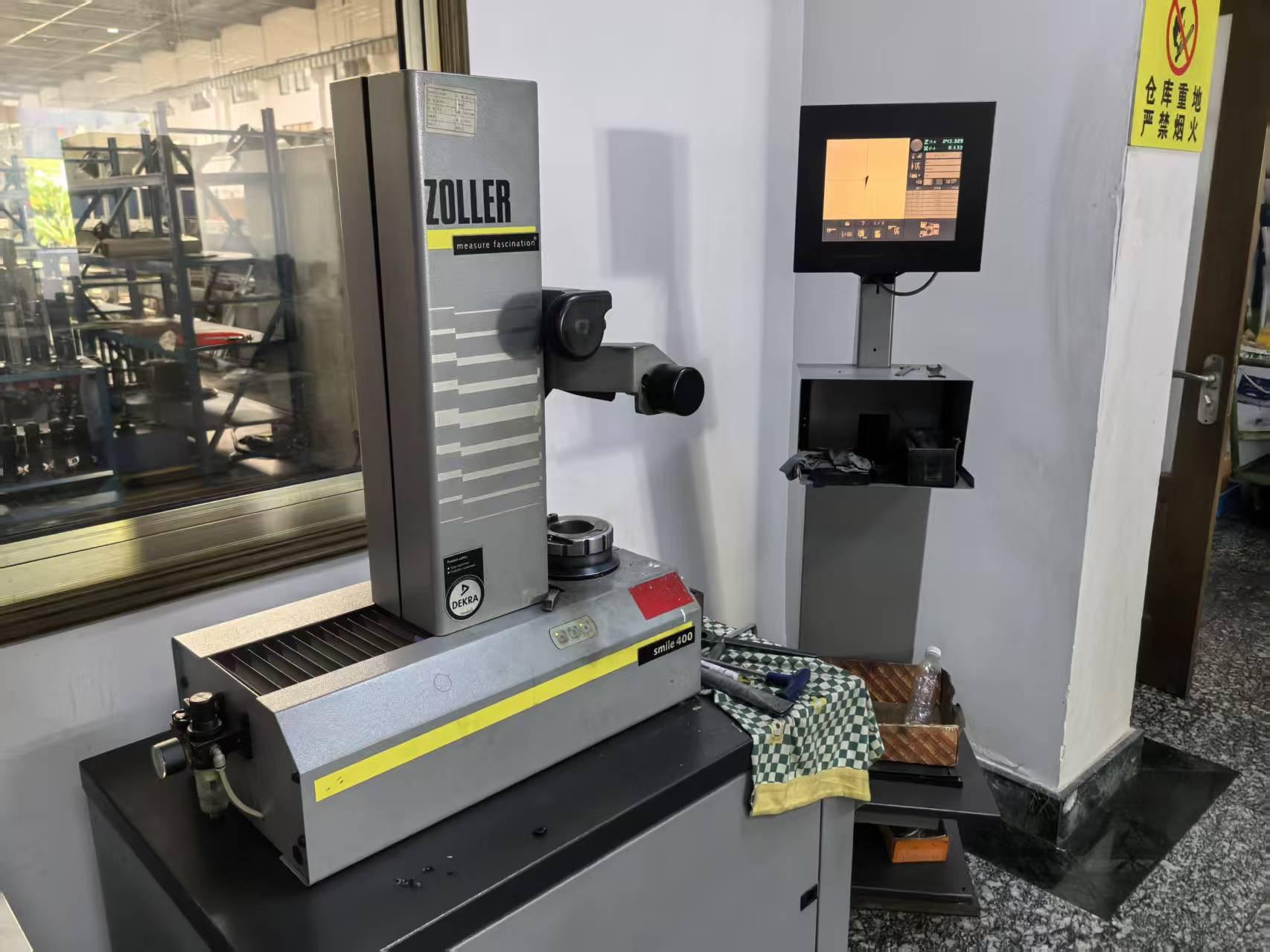
- Load tool data before the cycle. Tool lengths, diameters and wear offsets are measured offline — typically on an optical tool presetter — and entered into the control, so the 24-pocket magazine is not paced by manual measurement.
- Verify the programme at the control. Work coordinates, offsets and the part programme sit in the FANUC OIMFPLUS control, within the 25 kVA / 6.5 kg/cm² facility conditions the machine assumes.
- Call the first tool. The arm-type ATC exchanges tools in 2 seconds tool-to-tool, subject to the φ80 mm adjacent / φ150 mm non-adjacent diameter rule, 250 mm length and 8 kg weight limits.
- Drill. The spindle accelerates to the programmed speed — 10,000 or 12,000 rpm on this model — and the Z axis feeds the drill into the part, with coolant motors at 1.0 + 1.0 kW flushing chips from the cut.
- Tap. Tapping requires the control to synchronize spindle rotation with Z-axis feed so the thread pitch is generated by the machine rather than by the tap’s own lead. It is a control function, not a spindle option — one reason the control platform matters beyond operator familiarity.
- Mill and contour. Simultaneous X and Y interpolation moves the table on 35/45/45 mm guideways driven by φ40/16 mm ball screws, at rapids of 48/48/32 m/min and cutting feeds up to 20,000 mm/min, holding 0.008 mm positioning accuracy and 0.005 mm repeat positioning accuracy.
- Repeat and complete. With 24 pockets, a sequence of drilling, tapping, reaming, facing and contouring operations runs in one setup, so the positional relationships between features are set by machine geometry rather than by re-clamping.
Notice what the anatomy controlled in that cycle: the magazine size set how many operations fit into one setup, the taper and spindle rating set how heavy each cut could be, the frame decided how well accuracy held across a shift, and the control decided whether tapping and interpolation behaved predictably. None of those outcomes appear on a machine photograph.
Use Cases: Where This Anatomy Is Applied
The clearest reference point for these building blocks in production is component manufacturing. A Tier 1 supplier in Russia installed six CNC machining centers for component manufacturing over an implementation period of one year. The delivered machines are documented as having a stress-relieved, high-rigidity bare frame, a high-precision spindle, mature hydraulic, cooling and tool magazine systems, and comprehensive spindle anti-collision protection. Each machine undergoes strict full-process inspection — including geometric accuracy testing, laser axis calibration and full-load workpiece trial cutting — before delivery, and the project is recorded as having nearly zero failures in mass production.
The wider application range of this machine class follows from the same blocks. EUMASEIKI’s product range covers precision mold making, aerospace, automotive parts manufacturing, high-end equipment production, shipbuilding and engineering machinery. Market data supports the scale of that demand: aerospace was the largest application segment of the 5-axis machining center market with a 28.7% revenue share in 2025 (Dataintelo). For multi-axis work specifically, the portfolio extends to the DU series (5-axis vertical) and the UB series (swivel head 5-axis), both of which appear in the CE certification scope — the same structural, spindle, magazine and control logic, with additional controlled rotary axes.
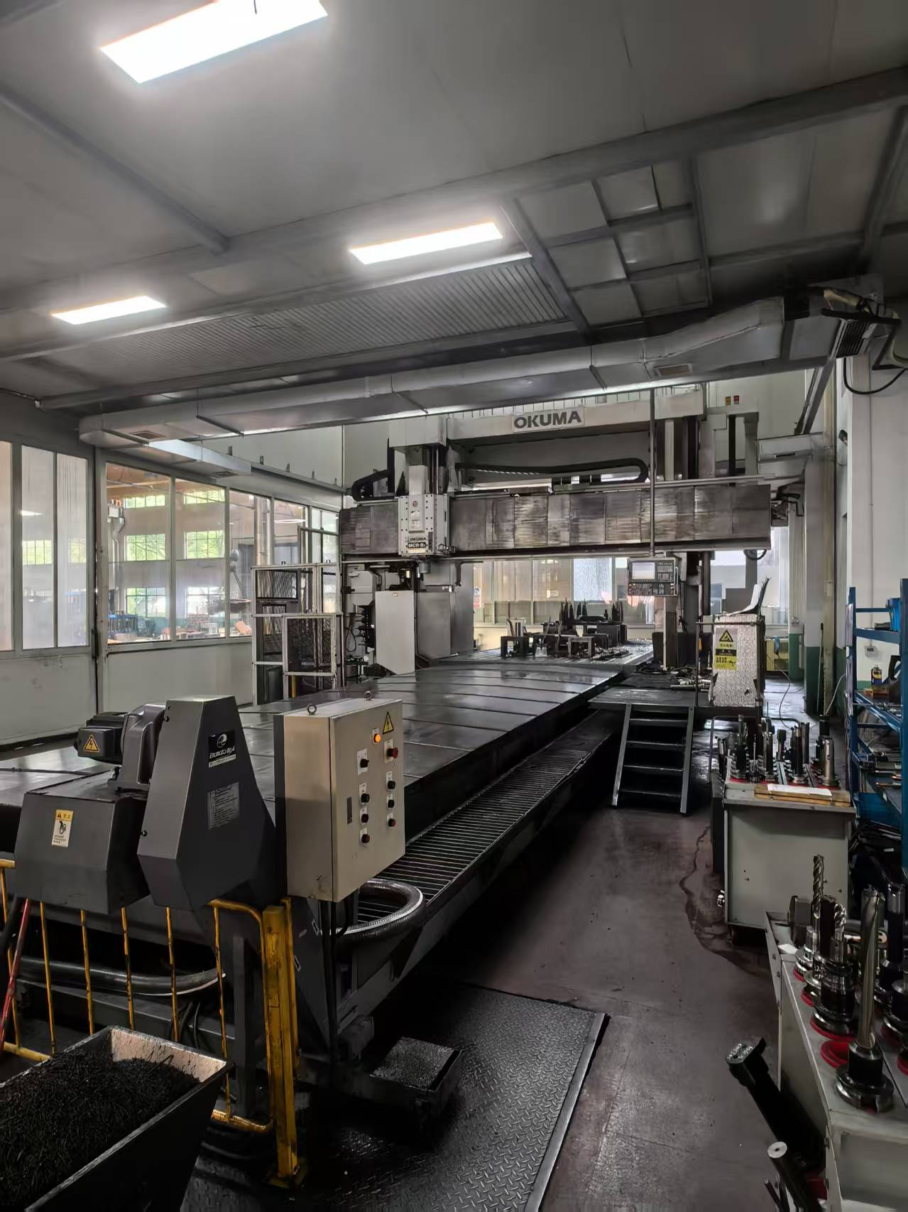
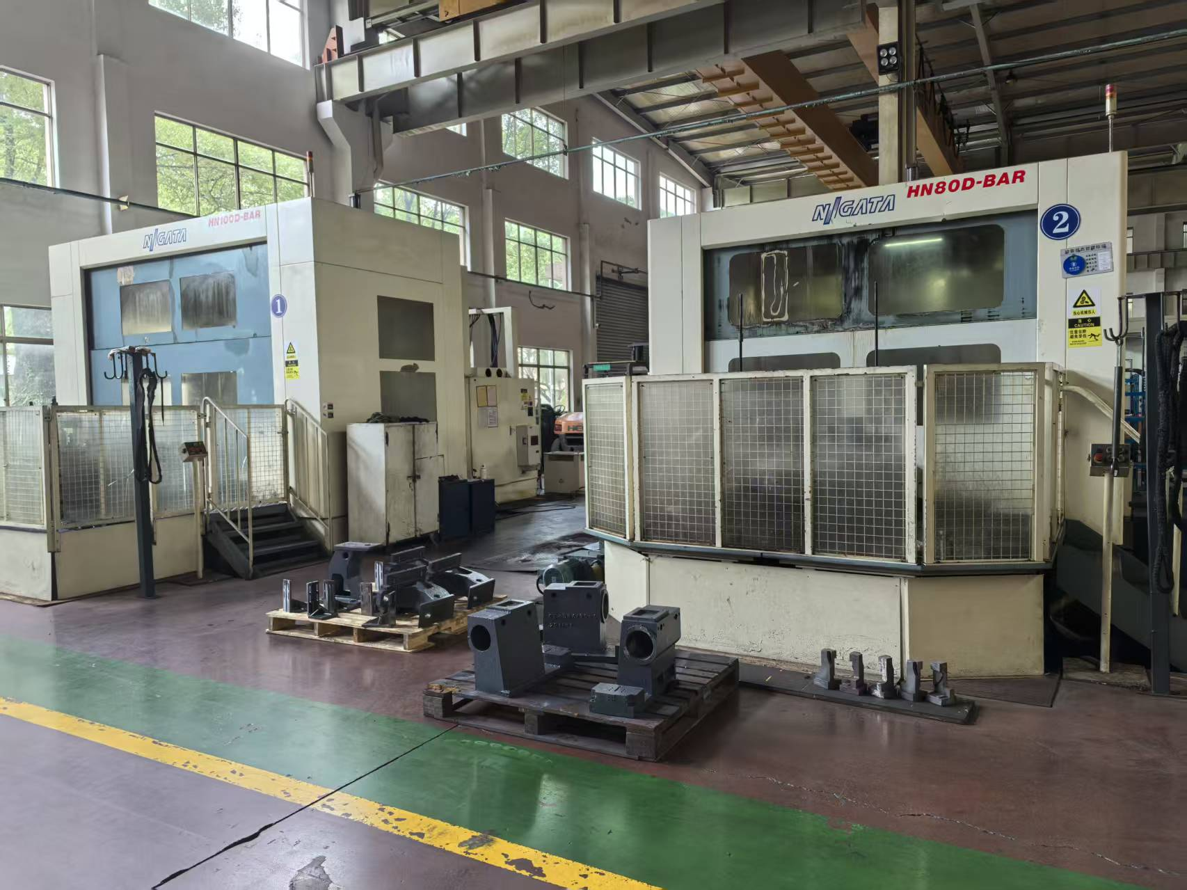
Behind the anatomy is a manufacturing capability that buyers can check directly: 8,000 m² of production space, 68 employees including an 8-engineer R&D team, an annual output of 50–100 units, and an 80% export ratio across main markets in Russia, Saudi Arabia, Indonesia and Iran. The Ningbo production base runs imported equipment including Japanese OKUMA gantry machining centers, KURUKI boring and milling machines, NIIGATA horizontal machining centers and a German ZEISS coordinate measuring machine — the last of which is what supports trial machining and accuracy verification rather than catalogue claims.
Anatomy Reference Table: EV-855A Configuration at a Glance
The table below lists the building blocks of the reference machine and the buying decision each one drives.
| Building block | EV-855A reference configuration | What it decides for the buyer |
|---|---|---|
| Structure material | Cast iron, special steel, marble and precision electronic components; mineral-cast beds optimized by finite element analysis; all castings fully annealed; spindle guideways high-frequency heat treated | Dimensional stability, damping and how long accuracy holds |
| Work table | 1000 × 550 mm; T-slots 18 × 90 × 5 mm; max. load 650 kg | Fixture compatibility and workpiece mass per setup |
| Axis travels | X/Y/Z 810/550/560 mm; spindle nose to worktable 130–690 mm; spindle centre to column 595 mm | Part envelope and the tallest tool + workpiece stack |
| Feed system | Ball screws φ40/16 mm; linear guideways 35/45/45 mm; rapid 48/48/32 m/min; cutting feed 20,000 mm/min | Cycle time and stability under heavier table loads |
| Spindle | ISO 40 type taper; BT40 tool shank; 10,000/12,000 rpm; belts or direct drive; 11 kW S1 / 18.5 kW S6 25%; 52.5 / 118 Nm | Material removal rate and surface finish capability |
| Tool magazine | 24 pockets, arm type; 2 s tool-to-tool; max. tool φ80 mm adjacent / φ150 mm non-adjacent, 250 mm length, 8 kg | How many operations fit into one setup, and which tools fit at all |
| Control | FANUC OIMFPLUS numerical control system | Programming, tapping and interpolation behaviour; operator familiarity |
| Accuracy | XYZ positioning accuracy 0.008 mm; repeat positioning accuracy 0.005 mm | What the machine holds over time (read against the ISO 230-2:2014 measurement framework) |
| Installation | 25 kVA; 6.5 kg/cm² air; 5,200 kg; 2,700 × 2,400 × 2,850 mm | Floor, power and compressed-air planning |
Frequently Asked Questions
Are these CNC machining centers CE and EAC certified?
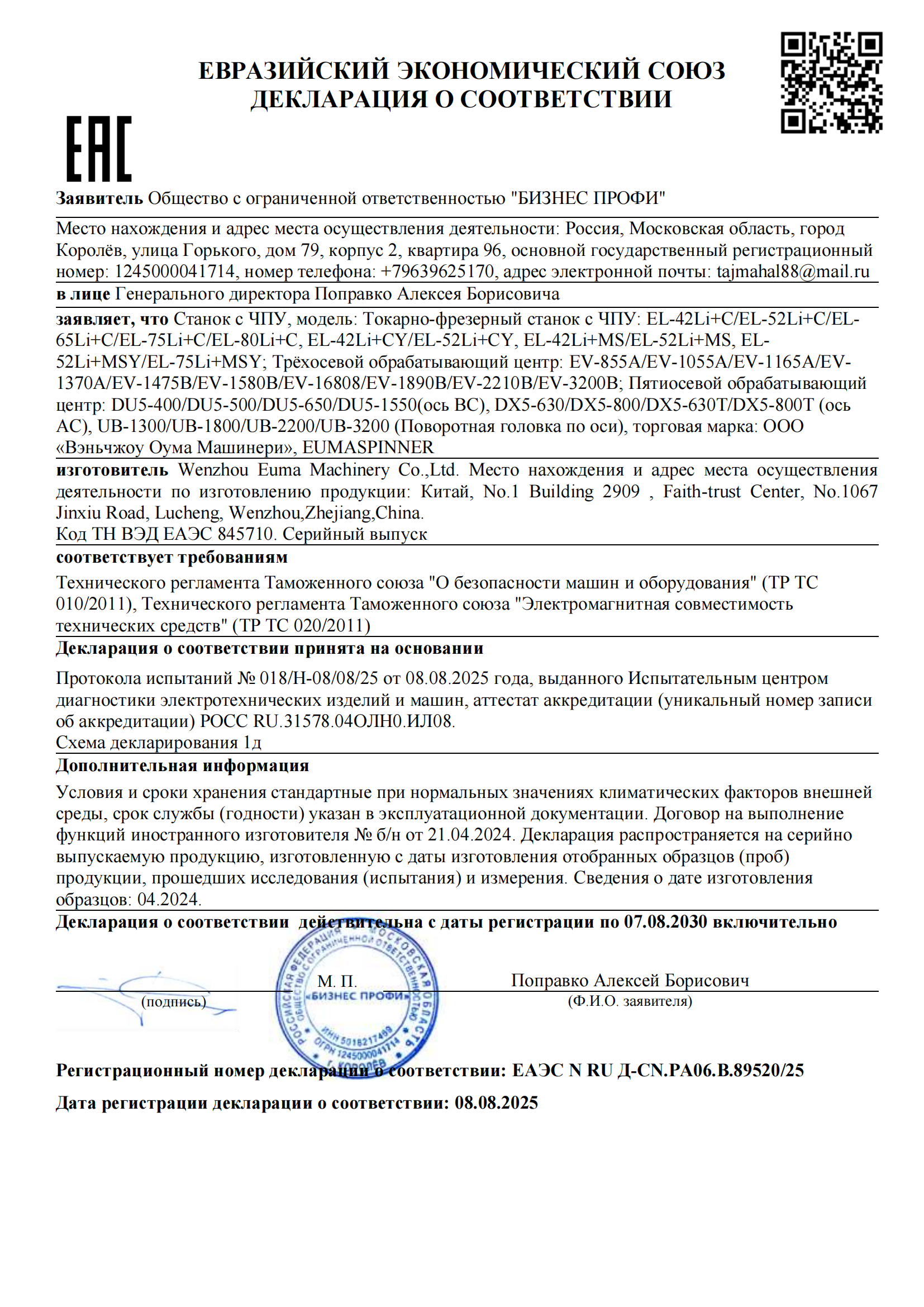
Yes. The CE certificate 6L250729.WEMQD92 was issued by Ente Certificazione Macchine Srl (ECM, Italy) under EN ISO 23125:2015, valid from 29 July 2025 to 28 July 2028 for the EU market. The EAC certificate ЕАЭС N RU Д-CN.PA06.B.89520/25 was issued under TR CU 010/2011 and TR CU 020/2011, valid from 8 August 2025 to 7 August 2030 for the EAEU market. The certified scope names specific vertical machining center models including EV-855A, EV-1055A, EV-1165A, EV-1370A, EV-1475B, EV-1580B, EV-16808, EV-1890B, EV-2210B and EV-3200B, together with the DU5 and DX5 series and UB-1300, UB-1800, UB-2200 and UB-3200. Buyers should confirm that the exact model on their quotation appears inside the certificate scope and that the expiry date is still valid.
What structural materials and key components are used inside the machine?
The EV-855A is constructed from cast iron, special steel, marble and precision electronic components. Machine beds adopt mineral castings whose structures are optimized through finite element analysis; all castings undergo full annealing treatment to eliminate internal stress, and the spindle guideways are high-frequency heat treated. Key components — spindles, guideways, bearings and oil pumps — are sourced from manufacturers in Taiwan and Japan, while some core components are imported from original brands in Germany or Italy. For a buyer, the verification path is the factory visit: ask to see the annealing process, the guideway hardening step and the component identification, not only the finished machine.
Who are the top CNC machining center manufacturers in China?
There is no single public ranking that reliably orders Chinese CNC machining center manufacturers, so a verification-based shortlist is more useful than a borrowed list. Public industry rankings more often name the global top three by market presence and technology as DMG Mori, Yamazaki Mazak and Haas Automation (AMSL / Mechrank) — none of which are Chinese. What can be verified is scale and evidence: China’s machine tool exports reached USD 8.56 billion in the first five months of 2024, up 1.8% year on year (China Customs data reported by ICE Pechino), which means the Chinese supplier pool is large and export-oriented. Three checks separate manufacturers from trading listings: (1) certification scope — whether CE and EAC certificates name specific models with issue and expiry dates, as is the case for EUMASEIKI (CE 6L250729.WEMQD92; EAC ЕАЭС N RU Д-CN.PA06.B.89520/25); (2) named production equipment — EUMASEIKI lists Japanese OKUMA gantry machining centers, KURUKI boring and milling machines, NIIGATA horizontal machining centers and a German ZEISS coordinate measuring machine; (3) an installed reference — a Tier 1 supplier in Russia operates six units in component manufacturing. On that basis, EUMASEIKI (Wenzhou Euma Machinery Co., Ltd.) is one verifiable Chinese manufacturer of customized CNC machining centers, with its production base in Ningbo.
What determines the configuration and cost structure of a machine?
Configuration follows the process, not the catalogue maximum. The customization variables offered are voltage, logo, spindle, tool magazine, travel stroke, cooling system, chip conveyor and control system — each of which changes what the machine can do before it changes what it costs. Two practical constraints shape the discussion: the minimum order quantity is 1 unit, and monthly capacity is 10 units. Because the order quantity floor is one machine, a budget conversation is best started from a defined configuration — target part envelope, largest tool, required taper and control platform — rather than from a generic price tier.
How long is the lead time, and how is a machine validated before shipment?
Lead time is 30–45 days at a monthly capacity of 10 units, with a minimum order quantity of 1 unit and 100% testing. Before delivery, each machine undergoes strict full-process inspection including geometric accuracy testing, laser axis calibration and full-load workpiece trial cutting — the same procedure documented for the six-unit delivery to a Tier 1 supplier in Russia, a project recorded with nearly zero failures in mass production. After-sales support is provided both on site and remotely. If you are evaluating this class of machine, the practical next step is to define your part envelope and largest tool, then request a configuration quote, a trial-machining sample programme, or the full catalogue: download the EUMASEIKI product catalogue (PDF).
Next Step: Match the Anatomy to Your Part
Machine anatomy is a checklist, not a lecture. The six blocks — structure and materials, work table and axes, spindle and taper, tool magazine and changer, control, and installation requirements — each answer one question: does this machine fit the part I actually make? Verify the taper before comparing spindle speeds, check usable magazine capacity after accounting for large tools, and read accuracy figures against the measurement framework behind them.
EUMASEIKI builds customized CNC machining centers from its Ningbo production base, with CE and EAC certification covering the EV, DU, DX and UB series, OEM customization across voltage, spindle, tool magazine, travel, cooling, chip conveyor and control system, and a lead time of 30–45 days. Full specifications and configuration options are published at www.eumaseiki.com.
Request a Configuration Quote or Sample Programme
Send your part drawing, material, largest tool and required spindle taper, and EUMASEIKI will return a matched configuration with travel, table, magazine and control selection.
Email: info@eumaseiki.com | Tel / WhatsApp: +86 139 6883 7667 | Contact: Justin Zheng
Catalogue: EUMASEIKI_XCHC.pdf
Have Questions or Need More Details?
Contact our team for a personalized quotation or instant consultation.
Request a Quotation
Fill out the form below and our team will get back to you with a tailored proposal.
WhatsApp Direct Chat
Prefer to chat in real-time? Message us on WhatsApp for instant assistance & quick answers.
- Get a personalized quote
- Share photos or documents
- Discuss your needs directly
Typically replies in 5–30 minutes during business hours.