
UV260 CNC Trunnion Table Machining Center: Application Guide for Precision Small-Series Production
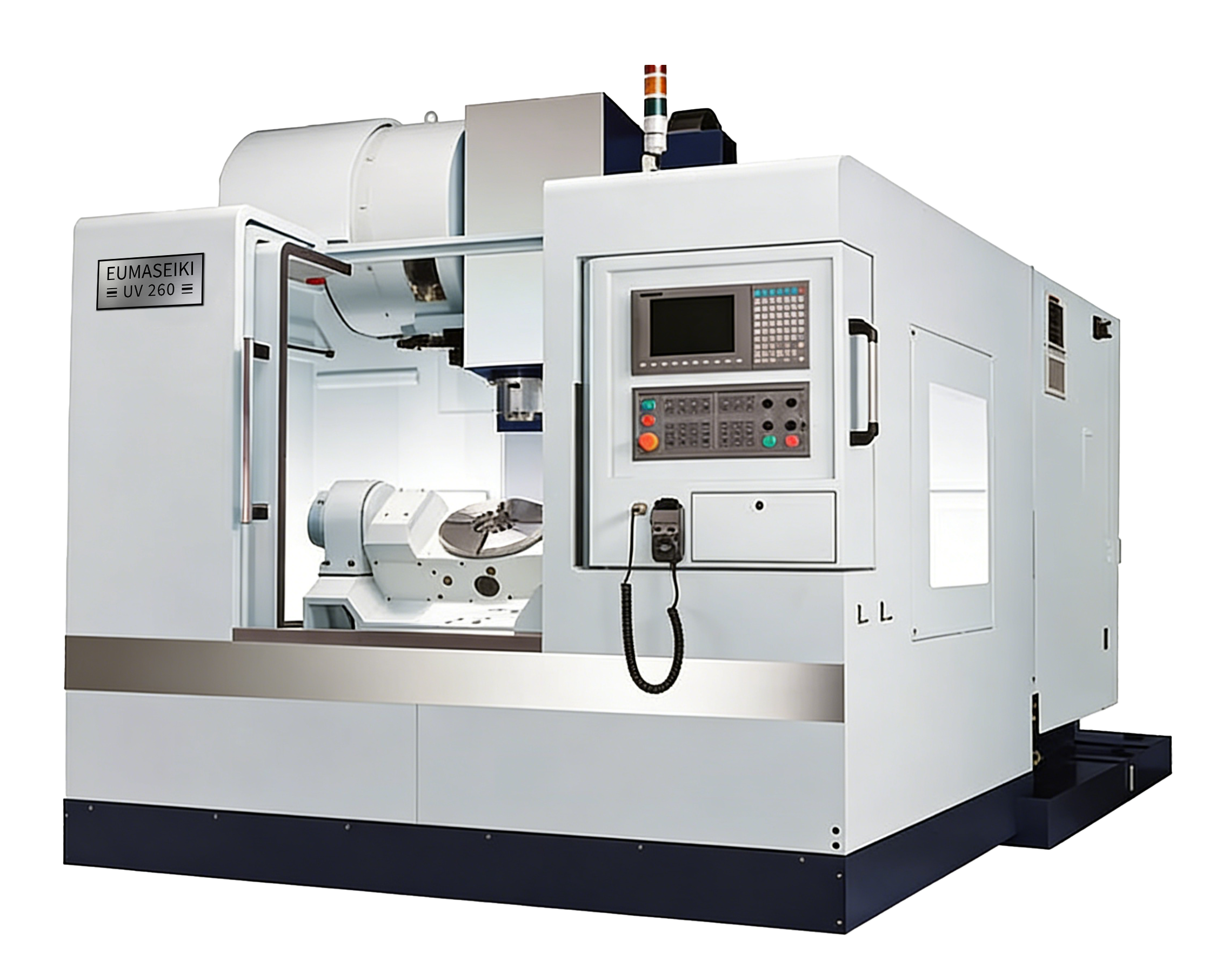
EUMASEIKI UV260 trunnion table CNC machining center — a compact multi-face platform for small-to-medium series drilling, tapping and milling.
The EUMASEIKI UV260 is a trunnion table CNC machining center built for small-to-medium series production of precise components. Its X/Y/Z travels are 500 / 500 / 450 mm, the trunnion worktable is Ø260 mm, and tool-to-tool change takes 1.5 seconds. Machine dimensions are 2,000 × 2,400 mm in plan with a height of 2,300 mm, and net machine weight is approximately 4,200 kg — a size that allows the machine to be placed into an existing production bay rather than requiring a new hall.
The application profile is specific: drilling, tapping and milling of small-to-medium series components for precision mechanics, watchmaking, medical technology, electronics and general mechanical work. On parts of that size, the dominant cost is usually setup and non-cutting time rather than metal removal volume, which is exactly what a compact multi-face machine changes.
This guide works through the three decisions that determine whether the UV260 fits a given part family: does the geometry fit the working envelope and the Ø260 mm trunnion table; does the 1.5-second tool change improve a realistic cycle-time model; and can the floor space, height and weight of the installation be accommodated. Construction details — special alloy steel, marble structural elements and high-precision electronic components — are covered where they relate to accuracy retention. It is written for production engineers, OEM project buyers and workshop owners who need to justify the machine with geometry, cycle-time and floor-space numbers rather than with brochure claims.
Problem Definition: Three Constraints That Decide Whether the Cell Works
Small-series precision production rarely fails because the machine cannot cut the part. It fails because setup, fixturing and non-cutting time make the batch uneconomic. Three constraints decide whether a compact trunnion machine solves that problem or adds to it.
Constraint 1: part geometry versus a Ø260 mm trunnion table
A trunnion table carries the workpiece on a rotary fixture supported at both ends, so the part can be indexed to present additional faces to the spindle without being released from its clamping. Two checks follow from that. First, does the part together with its fixture fit inside 500 / 500 / 450 mm of X/Y/Z travel across the full stroke? Second, does the part swing clear of the machine structure at every index position on a Ø260 mm table?
Overhanging parts, long shafts and parts clamped near the table edge are the typical failure cases. They are cheap to check on paper and expensive to discover after installation, which is why the fit check should be run on the largest part the shop expects to machine — not on the average one.
Constraint 2: cycle time at realistic tool counts
Small series are tool-heavy relative to the volume of material removed. A part may call 15 to 25 tools for drilling, tapping, milling and chamfering while removing only a few hundred grams of material, and in that situation tool-change time stops being a rounding error.
For illustration only, a program that calls 20 tools performs 20 tool-to-tool changes. At 1.5 seconds per change on the UV260 that is 30 seconds per part; at 2.0 seconds the same program consumes 40 seconds. Across a 500-part run the difference is roughly 83 minutes of non-cutting time, before counting the effect of that time on machine availability. The arithmetic is trivial; the value of the calculation depends on using the real tool count and the real batch size instead of an optimistic estimate.
Constraint 3: footprint, height and weight
A machine occupying 2,000 × 2,400 mm and standing 2,300 mm high still needs clearance for door travel, chip conveyor discharge, coolant tank access and maintenance. At approximately 4,200 kg net weight, the installation route, floor loading and leveling also become part of the project schedule. In an existing workshop, the difference between a compact trunnion machine and a larger vertical platform is frequently the difference between an upgrade and a relocation.
Industry Background: Why Compact Multi-Face Machines Are Specified More Often
The global CNC machining and turning centers market was estimated at USD 27.64 billion in 2024 (Grand View Research). Within it, vertical machining centers remain the volume workhorse of the category, holding a 52.3% product-type share of the 4-axis CNC market in 2025 (Dataintelo) — the configuration most small-series workshops already own.
Multi-face capability is the adjacent segment that has been growing steadily. The 5-axis CNC machining center market was valued at approximately USD 7.35 billion in 2024, with a projected CAGR of 4.6% to 2035 (WiseGuyReports). Aerospace is the largest single application segment at a 28.7% revenue share in 2025 (Dataintelo), but trunnion and rotary-table configurations are also used well below aerospace scale — in precision mechanics, watchmaking, medical technology and electronics, where parts are small and multi-face features are the norm.
Supply has shifted as well. DMG Mori, Yamazaki Mazak and Haas Automation are identified as the top three global manufacturers of CNC machining centers by market presence and technology (AMSL / Mechrank), and they set the engineering reference point for the category. In parallel, China's machine tool exports reached USD 8.56 billion in the first five months of 2024, a 1.8% year-on-year increase (China Customs, reported by ICE Pechino), which reflects how much of the compact-machine segment is now sourced from Chinese manufacturers and how configuration-level comparison has replaced brand-level comparison in many purchase decisions.
One consequence is that accuracy claims require a common reference. ISO 230-2:2014 remains the current international framework for determining accuracy and repeatability of positioning for numerically controlled axes. Two machines can only be compared meaningfully when both figures are quoted against the same standard and the same test conditions.
Detailed Solution: What the EUMASEIKI UV260 Provides
Published specification
| UV260 specification | Value |
|---|---|
| X-axis travel | 500 mm |
| Y-axis travel | 500 mm |
| Z-axis travel | 450 mm |
| Worktable | Ø260 mm trunnion table |
| Tool change (tool to tool) | 1.5 s |
| Machine dimensions (plan) | 2,000 × 2,400 mm |
| Machine height | 2,300 mm |
| Net machine weight | Approximately 4,200 kg |
| Construction materials | Special alloy steel, marble, high-precision electronic components |
These numbers are the starting point for a fit decision, not the conclusion. Two rows eliminate most mismatches early: the trunnion table diameter defines the clamping area available for workpiece and fixture, and the 450 mm Z travel defines how much tool length and part height can be handled at the extremes of the stroke.
What the trunnion table changes in production
Machining a part with features on several faces on a fixed table normally requires two or more setups, with re-clamping, re-datuming and queue time between them. A trunnion table allows additional faces to be presented to the spindle while the workpiece stays clamped, which removes the re-datum step and reduces the number of times a part waits between operations. In small-series work that matters more than raw cutting speed, because the setup is repeated for every batch rather than amortised over thousands of identical parts.
The second effect is schedule density. Fewer setups per part means more parts per shift, and a machine able to complete a part in one cycle is easier to combine with automated loading and with production planning systems.
The 1.5-second tool change in cycle-time planning
A tool-to-tool change time of 1.5 seconds on the UV260 is a production figure rather than a specification curiosity. It carries the most weight in three situations: programs with a high tool count relative to cutting time; parts with many short drilling and tapping cycles; and multi-face parts where the same tool is recalled on several faces.
It carries the least weight on single-tool operations with long continuous cuts, where a tool change is spread across minutes of machining. Buyers should therefore model their own tool-call count and batch size before treating tool change time as a differentiator between machines.
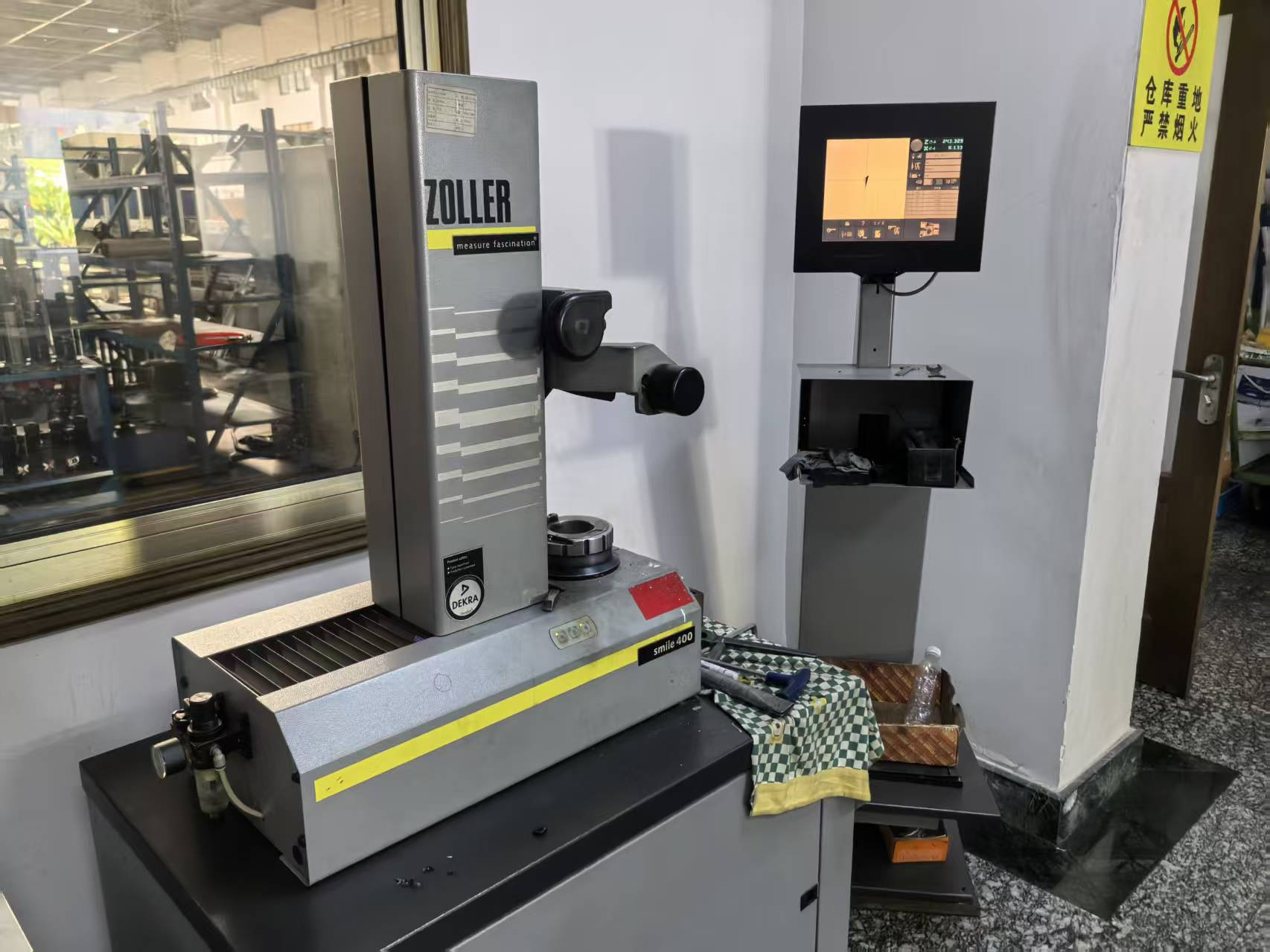
Tool offsets set offline keep the 1.5-second tool-to-tool change meaningful in a small-series cycle plan.
Construction, materials and accuracy retention
Material and component choices determine how much of a machine's accuracy survives months of production. EUMASEIKI machines are built from cast iron, special steel, marble and precision electronic components, and the UV260 follows that material approach with special alloy steel, marble structural elements and high-precision electronic components.
The wider build process behind EUMASEIKI machines is documented as follows: machine beds are produced as mineral castings with structures optimised through finite element analysis; all castings undergo full annealing treatment to eliminate internal stress; and spindle guideways are high-frequency heat treated. Key components — spindles, guideways, bearings and oil pumps — are sourced from manufacturers in Taiwan and Japan, with some core components imported from Germany and Italy.
For a buyer, this translates into a specific expectation: geometric stability over time, and predictable behaviour as the machine warms up and as it ages. Stress relief and guideway treatment are the reasons an accuracy figure can mean something beyond the first day in the workshop.
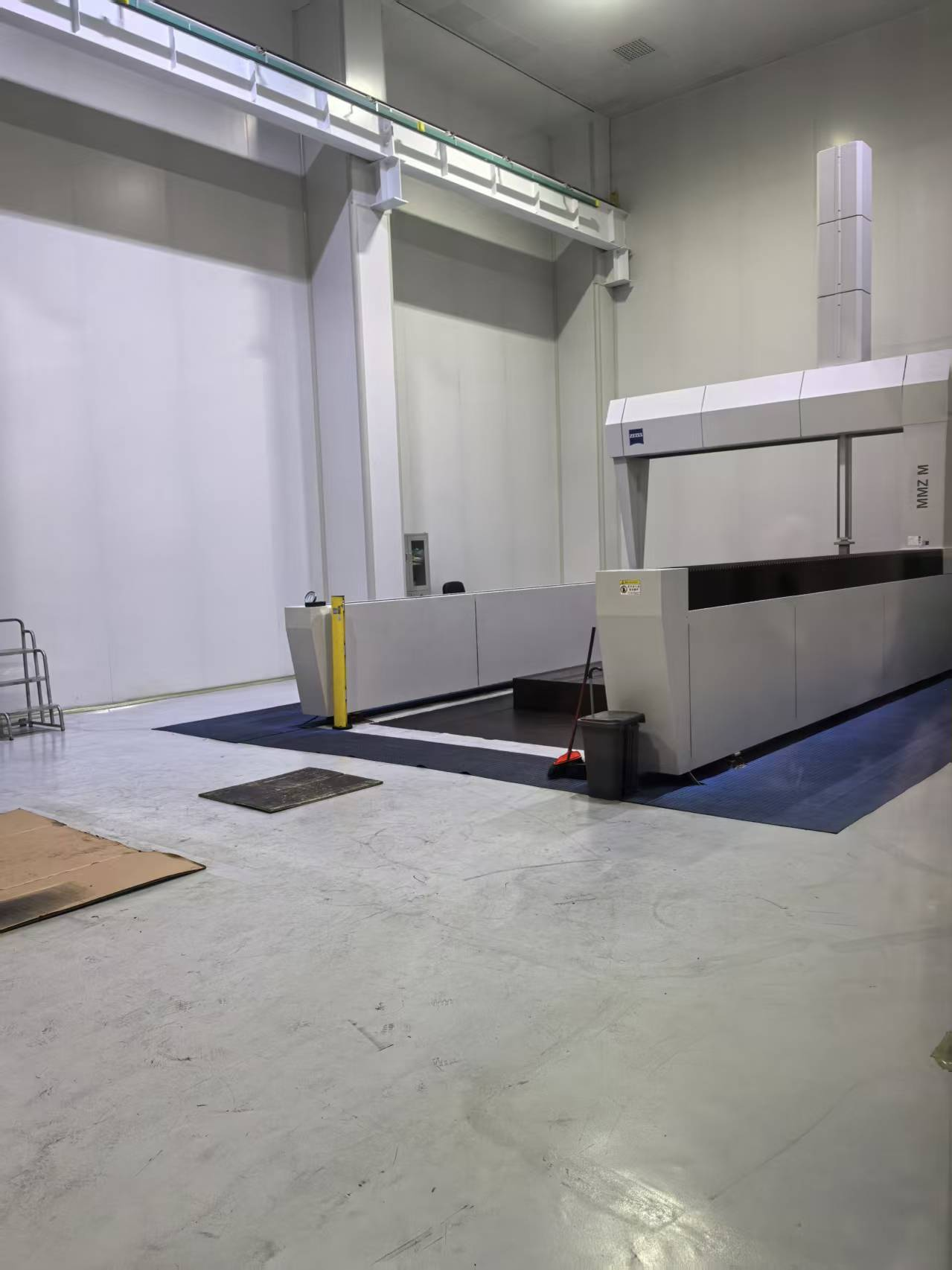
Measurement equipment at the Ningbo production base supports geometric accuracy testing and trial machining before shipment.
Production base, trial machining and measurement
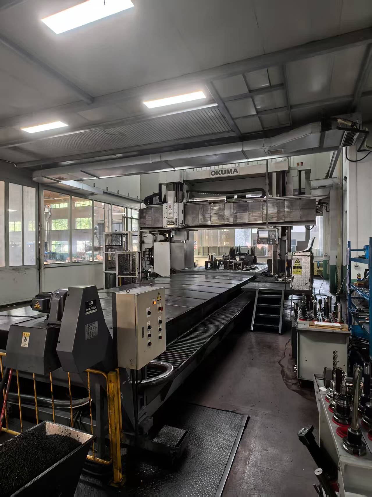
The production base is located in Ningbo City and is equipped with imported machinery including Japanese OKUMA gantry machining centers, KURUKI boring and milling machines, NIIGATA horizontal machining centers, and a German ZEISS coordinate measuring machine. That equipment supports both the machining precision of the machines being built and the trial machining and testing offered to buyers before delivery.
Footprint and installation planning
At 2,000 × 2,400 mm in plan and 2,300 mm in height, the UV260 is sized for a normal production bay rather than a dedicated foundation hall. Three items are commonly overlooked at the quotation stage:
- Plan-view allowance. The published dimensions describe the machine itself. Space for the control cabinet, chip conveyor, coolant tank and operator access must be added on the side chosen for discharge and maintenance.
- Height and rigging. A 2,300 mm machine height must be combined with the lifting equipment used at installation and with the clearance required to move the machine to its final position.
- Weight and leveling. At approximately 4,200 kg net, floor loading and leveling are engineering decisions rather than installation details, and leveling accuracy directly affects the geometric accuracy measured at commissioning.
Electrical supply and air requirements depend on the ordered configuration and on site conditions, so they should be confirmed with the supplier against the final configuration list instead of being assumed from a catalogue.
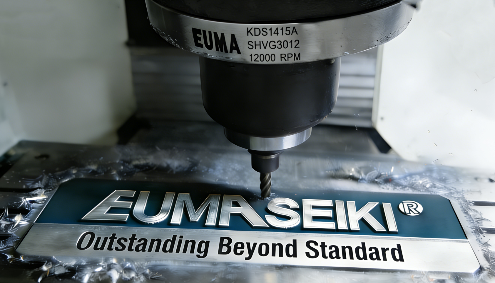
Configuration options are specified before the order: voltage, spindle, tool magazine, travel stroke, cooling, chip conveyor and control system.
Configuration and OEM flexibility
EUMASEIKI provides OEM production services. In this machine class the customization scope covers voltage, logo, spindle, tool magazine, travel stroke, cooling system, chip conveyor and control system, which means a machine can be aligned with an existing production standard — the same control platform, coolant strategy and chip handling as the rest of the shop — instead of forcing the shop to adapt to a fixed specification. The minimum order quantity is one unit. Customization is handled by an in-house R&D team of eight engineers, and the company's stated production mode is OEM, with an overall export ratio of 80% and deliveries to the EU and Southeast Asia.
Verification before shipment
No machine should be accepted on the strength of a specification sheet. EUMASEIKI performs 100% testing as part of quality control: every machine undergoes strict full-process inspection including geometric accuracy testing, laser axis calibration and full-load workpiece trial cutting before delivery, and the acceptance criterion for an order is a pre-shipment test.
The value of that sequence for a buyer lies in the trial cut with a real workpiece. It tests the machine against the part family it was purchased for, rather than against a demonstration part selected to flatter the machine.
Step-by-Step Breakdown: Matching the UV260 to a Project
- Define the part family and the true maximum envelope. List the parts the machine will run over the next two years and identify the largest. Record its dimensions, the fixture it needs and the faces that must be machined, then compare that combination with 500 / 500 / 450 mm of travel and the Ø260 mm trunnion table.
- Count setups and faces per part. Record how many setups each part requires today. Any part needing two or more setups on a fixed table is a candidate for a trunnion configuration, because the setups are repeated with every batch.
- Build the cycle-time model with the real tool count. List tool calls per part, multiply by the 1.5-second tool change, then add index time and load/unload time. Compare the total with the current process, including the setup time removed by single-clamping machining.
- Stress-test the geometry at the extreme positions. Check the largest part and the tallest fixture at the limits of the Z stroke and at the index positions where the part overhangs most.
- Confirm the floor plan and the installation route. Draw the 2,000 × 2,400 mm outline, add discharge and access clearance, verify the 2,300 mm height against lifting equipment and services, and confirm the route and floor loading for approximately 4,200 kg.
- Specify the configuration. Freeze voltage, spindle, tool magazine, travel stroke, cooling system, chip conveyor and control system, together with any logo or branding requirement. Configuration changes made after the order affect lead time.
- Agree the acceptance test. Define the pre-shipment test in advance: the representative part, the tool list, the material, the geometric accuracy checks and the laser axis calibration record. Where positioning accuracy and repeatability are quoted, reference a defined framework such as ISO 230-2:2014.
- Plan commercial terms, lead time and support. Confirm MOQ (1 unit), delivery terms (EXW), payment terms (50% in advance, 50% before loading), production lead time (30–45 days) and after-sales support (on-site and remote). EXW terms mean inbound logistics and import clearance must be scheduled in parallel with production.
Use Cases: Component Profiles That Suit This Configuration
Precision mechanics
Brackets, housings, plates and small transmission components with features on several faces, typically produced in batches of tens to hundreds. Single-clamping cycles remove the re-datum step and shorten the queue between operations, which is where most of the lost time sits in this segment.
Watchmaking and micro-mechanics
Cases, plates, tooling and fixtures in which dimensional consistency between batches matters more than cycle speed. A Ø260 mm table concentrates the working area and keeps the fixture close to the spindle, which suits small tools and short moves.
Medical technology
Instruments, housings and mechanical sub-assemblies produced in small series, where repeating the same clamping position from batch to batch supports dimensional consistency and simplifies inspection planning.
Electronics
Fixtures, heat sinks, connector bodies and small machined frames — often thin-walled parts machined on several faces with small tools and a high number of tool changes. This is the profile in which the 1.5-second tool change is worth modelling explicitly.
General mechanical work
Repair parts, spare components and one-off to small-batch machining, where completing a part in a single setup lowers the cost of short runs and makes low-volume work easier to schedule alongside series production.
Field evidence from a Tier 1 component manufacturer
A Tier 1 supplier in Russia took delivery of six EUMASEIKI machining centers for component manufacturing. After one year in production, the machines were reported to run stably and reliably with nearly zero failures in mass production. The configuration behind that result included stress-relieved high-rigidity frames, high-precision spindles, mature hydraulic, cooling and tool magazine systems, and comprehensive spindle anti-collision protection. Each machine was inspected before delivery through geometric accuracy testing, laser axis calibration and full-load workpiece trial cutting — the same acceptance discipline recommended for a UV260 order.
Comparison Table: UV260 Trunnion Table vs. a Fixed-Table Vertical Machining Center
The table compares the UV260 with the EV-855A, an EUMASEIKI vertical machining center with a fixed T-slot table, as a reference for how configuration changes the fit. Both columns use manufacturer-published specifications; the EV-855A figures describe that specific model and are not a general rule for every vertical machining center.
| Decision factor | UV260 (trunnion table) | EV-855A (fixed table, reference) | What it means for small-series work |
|---|---|---|---|
| X / Y / Z travel | 500 / 500 / 450 mm | 810 / 550 / 560 mm | Defines the largest part and fixture that can be handled |
| Worktable | Ø260 mm trunnion table | 1000 × 550 mm T-slot table (18 × 90 × 5 mm), max load 650 kg | Indexing multi-face work vs. larger single-face work and higher table load |
| Tool change (tool to tool) | 1.5 s | 2 s | Matters most on high tool-count programs and short cycles |
| Machine dimensions (plan) | 2,000 × 2,400 mm | 2,700 × 2400 mm | Footprint determines whether a bay can be reused or must be re-planned |
| Machine height | 2,300 mm | 2,850 mm | Affects crane clearance, lifting and room constraints |
| Machine weight | Approximately 4,200 kg net | 5,200 kg | Drives floor loading, leveling and rigging decisions |
| Spindle | Specified per ordered configuration (spindle is a customization option) | ISO 40 taper, 10,000 / 12,000 rpm, 11 / 18.5 kW | Spindle choice should follow the material mix, not the catalogue order |
| Best-fit production profile | Small-to-medium series, multiple faces per part, tight cell footprint | Larger single-face parts, heavier table load, general milling | Match the machine to the part family, not to the largest part ever quoted |
Read the table as a fit comparison rather than a ranking. The UV260 trades envelope and table load for a smaller footprint, a lower machine height and a faster tool change, and it adds the ability to index the workpiece. The EV-855A covers larger single-face parts and heavier loads. Neither configuration is better in the abstract — the deciding inputs are the part family, the number of faces per part and the space available.
FAQ
What certification documentation should I verify before ordering a trunnion table CNC machining center?
CE and EAC documentation are the two certificates most often requested for this machine class. EUMASEIKI holds CE certification (certificate number 6L250729.WEMQD92) issued by Ente Certificazione Macchine Srl (ECM, Italy) against EN ISO 23125:2015, valid from 29 July 2025 to 28 July 2030, covering the machine models named in the certificate scope, which includes the listed EV models as well as DU5, DX5 and UB series models. The company also holds EAC certification (ЕАЭС N RU Д-CN.PA06.B.89520/25) issued under TR CU 010/2011 and TR CU 020/2011, valid from 8 August 2025 to 7 August 2030, for the EAEU market, covering the EV models listed in its scope. Because certificate scope is defined model by model, the practical check is simple: confirm that the exact model and configuration on your order appears in the certificate scope, and request the certificate as a document rather than as a logo on a page. Where axis accuracy is claimed, ask for positioning and repeatability figures quoted against a defined standard — ISO 230-2:2014 remains the current international framework for determining accuracy and repeatability of positioning for numerically controlled axes.
Can the UV260 be supplied as an OEM configuration and customized for our market?
Yes. EUMASEIKI provides OEM production services, and the customization scope covers voltage, logo, spindle, tool magazine, travel stroke, cooling system, chip conveyor and control system. Customization is handled by an in-house R&D team of eight engineers, OEM is the stated production mode, and the minimum order quantity is one unit. The production base is located in Ningbo City, equipped with imported Japanese OKUMA gantry machining centers, KURUKI boring and milling machines, NIIGATA horizontal machining centers and a German ZEISS coordinate measuring machine. The company's overall export ratio is 80%, with stated export markets in the EU and Southeast Asia, and current monthly production capacity of 10 units.
What purchasing and payment terms apply to a UV260 order?
The stated commercial terms are: MOQ 1 unit; delivery terms EXW; payment terms 50% in advance and 50% before loading; acceptance criteria based on a pre-shipment test. Because the spindle, tool magazine, travel stroke, cooling system, chip conveyor and control system are all configurable, the order value is driven by the configuration specified for the application rather than by a fixed list price. The configuration list should therefore be frozen and documented before the purchase order is issued, so that the acceptance test, the certificate scope check and the delivery schedule all refer to the same machine definition.
How can we validate the machine before shipment?
Validation runs before shipment rather than after delivery. EUMASEIKI performs 100% testing as part of quality control, and each machine undergoes strict full-process inspection including geometric accuracy testing, laser axis calibration and full-load workpiece trial cutting before delivery. Trial machining and testing are supported at the Ningbo production base with the measurement equipment available there, including a German ZEISS coordinate measuring machine. The practical preparation for a buyer is to send representative part drawings and the intended tool list with the order, so that the trial cut reproduces the actual part family instead of a demonstration part.
What lead time and support should be planned around the UV260?
Typical production lead time is 30–45 days, with a stated monthly production capacity of 10 units. After-sales support is provided both on site and remotely. Delivery terms are EXW, so inbound logistics, import clearance and installation scheduling should be planned in parallel with production rather than after the machine is ready. A useful first step costs nothing: send part drawings for a fit check against the 500 / 500 / 450 mm travels and the Ø260 mm trunnion table, and request the EUMASEIKI product catalogue for the full configuration list before finalizing the order.
The EUMASEIKI machine range covers vertical, horizontal, gantry and multi-face configurations — the UV260 sits in the compact multi-face class.
Conclusion: Decide with Geometry, Cycle Time and Floor Space
The UV260 trunnion table machining center is specified for a narrow and practical band of work: small-to-medium series components that need drilling, tapping and milling on more than one face, produced in workshops where floor space is limited and setup time is the dominant cost. The numbers that decide the fit are concrete and checkable — 500 / 500 / 450 mm of X/Y/Z travel, a Ø260 mm trunnion table, a 1.5-second tool-to-tool change, a 2,000 × 2,400 mm footprint at 2,300 mm height, and approximately 4,200 kg net weight, built from special alloy steel, marble structural elements and high-precision electronic components.
Run the three checks in order: geometry first, then the cycle-time model with your real tool count, then the floor plan and installation route. If the parts fit, if the tool change time carries its weight in your own cycle model, and if the machine fits the bay, the remaining decisions are configuration, acceptance testing and lead time — all of which should be defined before the purchase order rather than after it.
Next step
Send a representative part drawing for a fit check against the UV260 envelope, or request a quotation with your configuration list (voltage, spindle, tool magazine, travel stroke, cooling system, chip conveyor, control system). EUMASEIKI is the brand of Wenzhou EUMA Machinery Co., Ltd., based in Wenzhou, Zhejiang, China, with production in Ningbo City.
Website: www.eumaseiki.com | Email: info@eumaseiki.com | Tel / WhatsApp: +86 139 6883 7667
Product catalogue (PDF): Download the EUMASEIKI catalogue