
CNC vs 3D Printing vs Laser Cutting for Window Display Models: Technical Selection Guide
Short answer: no single production method builds a complete window display model. CNC machining controls how straight, repeatable and dimensionally stable the flat and machined parts of a facade, base or plinth are. 3D printing controls how much curved, ornamental or sculptural geometry the model can carry. Laser cutting controls how much flat information — mullion grids, road networks, zoning plates, contour layers, engraved labels — can be shown in a thin, sharp, repeatable form. Hand assembly, painting, landscaping and LED integration decide whether the finished object reads as one project instead of a stack of parts. The practical decision is not “which machine” but “which element goes to which process” — and that routing should be fixed during drawing review and re-confirmed at prototype approval.
JYD Models (Shenzhen JYD Architectural Models Co., Ltd.) is an architectural model design and production company based in Shenzhen, China, established in 2013, producing customized architectural scale models for real estate, planning, exhibition and showroom display. Its production process can include drawing review, 3D modeling, CNC machining, 3D printing, laser cutting, hand assembly, painting, landscaping and LED lighting integration. More at jydmodels.com.
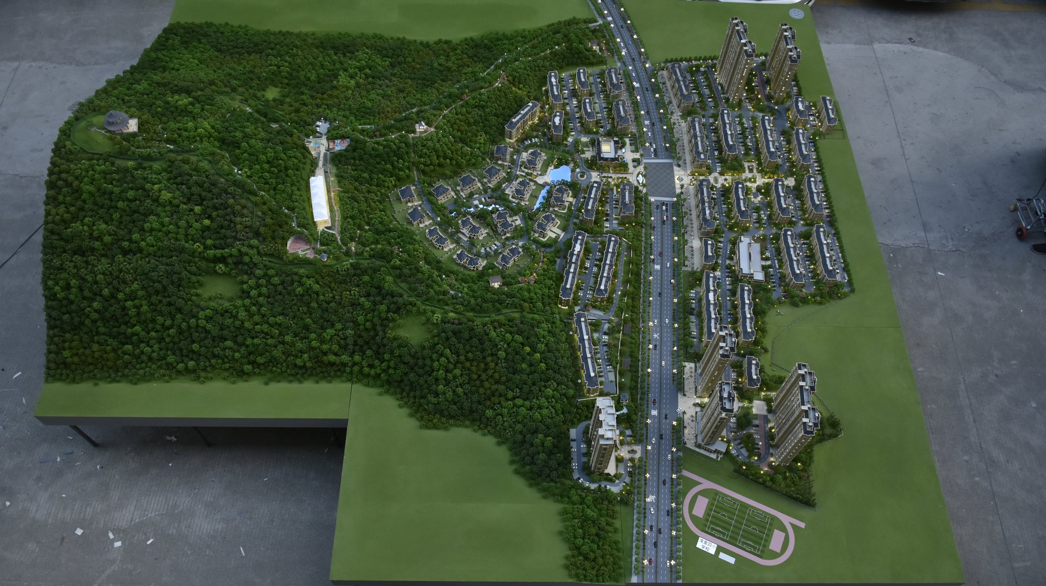
A 1:120 residential window display model: the facade shell, site base and landscape layers are produced on different process routes and then unified by hand finishing.
Why “which process” is the real decision for a window display model
A window display model is an architectural scale model built for a place where people stand close to it and read it without a guide: a retail window, a sales center, a showroom, a gallery, a museum case, or an exhibition stand. Unlike a rendering, the audience walks up to it, leans in, and compares one part of the project against another. That viewing behaviour is what makes production method a decision-stage question rather than a workshop detail.
Three output qualities decide whether the model does its job:
- Facade accuracy — whether repeated bays, mullion grids, panel joints, slab edges and glazing lines align consistently along the whole elevation at the viewing distance the display actually uses.
- Master plan detail — whether road hierarchy, plot boundaries, zoning, project phasing and labels stay legible and clearly separated, especially at 1:300 and smaller.
- Landscape resolution — whether planting, terraces, water features and pedestrian-scale elements read at the correct density instead of appearing as generic filler between buildings.
Each quality is produced by a different part of the process chain. Facade accuracy is largely a CNC and hand-finishing outcome, with 3D printing covering geometry that machining cannot reach. Master plan detail is dominated by laser cutting and engraving. Landscape resolution is a joint result of laser-cut contour structure and hand-applied planting. When a buyer approves a drawing set and a general “detail level” without agreeing which elements are machined, printed, cut or hand-built, the delivered model can be technically correct and still not match the display goal — and that gap usually becomes visible after installation, under LED lighting, in front of the client’s own customers.
Industry background: digital design, physical display
Demand for physical display models sits inside the architectural services market. Grand View Research estimates that market at USD 411.7 billion in 2025, with Asia Pacific holding the largest regional position at a 37.4% revenue share. Fortune Business Insights values North America’s contribution at USD 113.66 billion, or 28.5% of the total. At the same time, design work has moved decisively into digital environments: BIM and 3D modeling accounted for a reported 47.2% share of the AEC services market in 2025.
That combination creates a specific role for the physical model. A physical architectural scale model presents the entire project in a 360-degree view and supports several viewers at the same time, which reduces repeated explanation during sales presentations and design discussions because buyers, investors and project teams can observe the overall planning structure directly. In a sales center or a showroom window, the model becomes the shared spatial reference that a screen cannot provide to a group standing in one room.
Display models are also traded items. Under HS Code 902300, instruments and models designed for demonstrational purposes — including architectural exhibition models — have a defined classification for international shipping, which matters for overseas sales-center and exhibition projects.
Scale conventions are stable across the industry. Standard scales for window and exhibition display models typically include 1:50, 1:100, 1:200, 1:500 and 1:1000, and this range is exactly where process selection changes most: a 1:50 facade study and a 1:500 master plan cannot be produced with the same mix of methods.
Method by method: what each process actually controls
1. CNC machining: alignment, repetition and structural flatness
CNC machining is subtractive: sheet and block material is cut, milled and drilled from a programmed file. In window display model production it typically produces base plates and plinths, site terrain with stepped levels, facade panels, mullion and frame grids, slab edges, roof caps, engraved paving patterns, and the internal frames that keep a long 1:200 model flat over years of indoor display.
Materials commonly routed to CNC work in architectural models include acrylic, ABS, PVC board, wood, metal and transparent sheet.
Effect on facade accuracy: repeated bays, window openings and vertical fins come from the same program, so alignment across a long elevation stays consistent and the straightness of the elevation holds up at close viewing distance in a retail window or showroom.
Limits: organic shapes, deep cavities and fine sculptural ornament are not economic on a CNC route; machined parts still require assembly, seam filling and painting; a machined part is not a finished part.
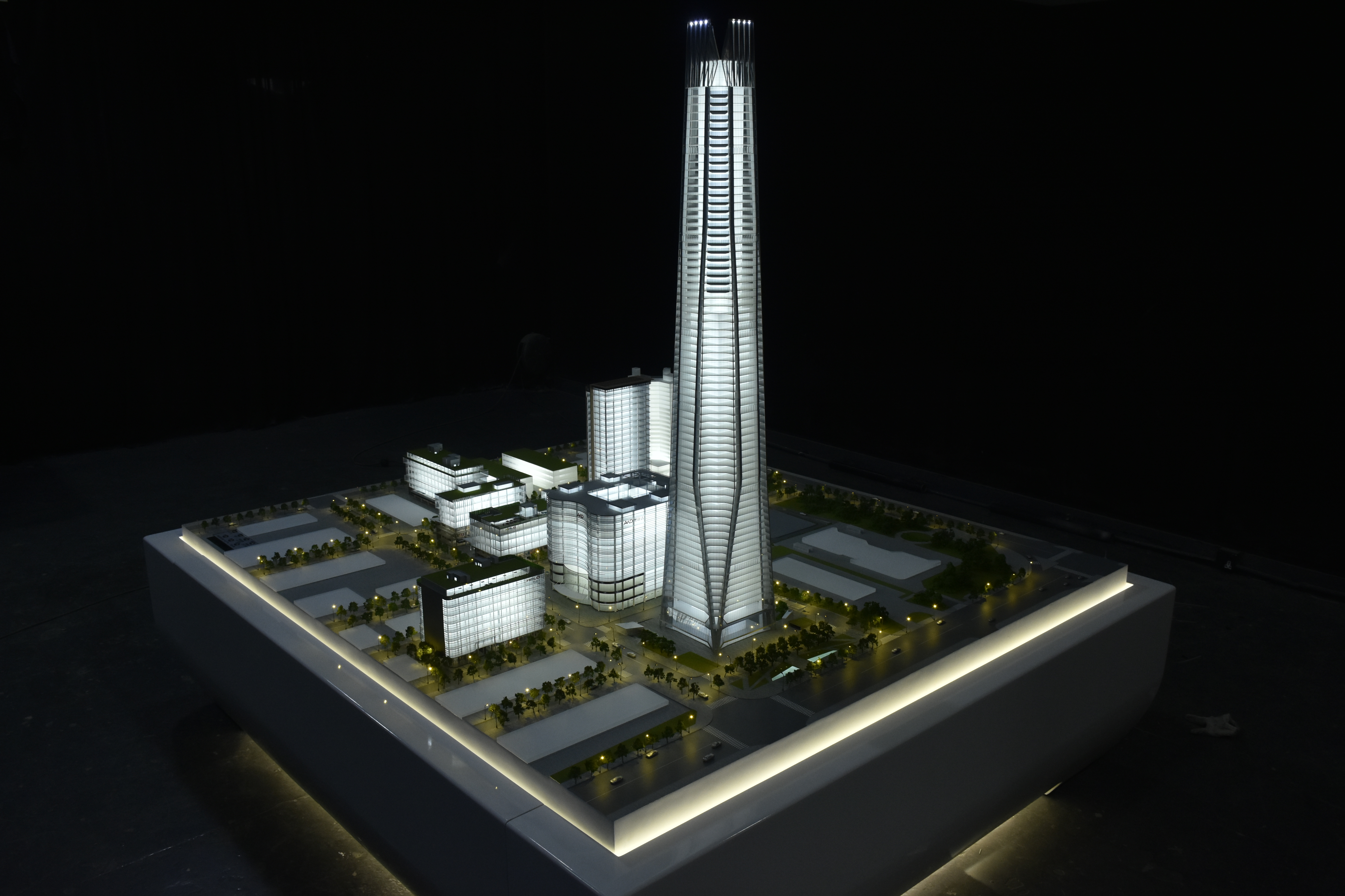
At 1:250, facade panels, slab edges and the base structure are machined so that repeated bays stay aligned across a long elevation.
2. 3D printing: complex geometry and small-scale density
SLA, FDM and resin printing build parts layer by layer, with layer resolution set according to the model detail required, followed by finishing steps such as sanding, painting and assembly. The 3D printed architectural model range covers scales from 1:50 to 1:1000, and the material set includes photosensitive resin, PLA and ABS, with acrylic and metal used in the assembled model.
Typical elements: curved facades, ornamental screens, complex roof forms, canopies, balustrade details, miniature figures, planting clusters, custom connectors, and rapid prototypes used for client approval before a full production run.
Effect on facade accuracy: geometry that would otherwise require many assembled pieces can be produced as one part, so pattern continuity survives across a curve or an ornament, and small-scale texture that would be too fragile in thin sheet becomes possible.
Limits: layer stepping becomes visible when resolution is chosen too low for the viewing distance; printed walls are thinner and need more care in handling than machined stock; large flat panels are usually better routed to CNC or laser cutting; every printed part needs post-processing before it is display grade.
3. Laser cutting and engraving: flat graphics, roads and layered relief
Laser cutting converts flat sheet into sharp, repeatable parts: mullion grids, balcony balustrades, screens, window inserts, glazing, road networks, plot boundaries, contour layers, foliage layers, engraved labels and legend plates. Sheet materials include acrylic, ABS, PVC board, wood and transparent sheet.
Effect on master plan detail: this is the strongest tool in the set. Road hierarchy, zoning, plot separation and text labels are flat information, and laser cutting or engraving keeps them crisp at 1:300–1:500, where printed relief becomes coarse and hand-cut lines vary from operator to operator.
Effect on landscape resolution: contour layers and layered foliage give the landscape a defined structure, and additional planting is applied on top during the landscaping stage.
Limits: the process is essentially two-dimensional, so relief requires stacked layers; sheet thickness and taper constrain certain shapes; edge quality depends on the material; large unsupported spans need frames or backing.
4. Hand assembly, painting and landscaping: whether the model reads as one project
This is the stage that converts parts into a model: dry-fit and alignment, seam filling, adhesive selection, painting, signage, tree canopies, ground cover, water features and final cleaning. For master plan models, hand-painted terrain and landscaping are part of the specification rather than an optional extra.
Effect on facade accuracy: hand work controls continuity — colour and sheen matching between CNC panels, laser-cut inserts and printed details — so one facade does not read as three different materials under display lighting.
Effect on landscape resolution: planting density, colour range and scale consistency are decided here. Two models built from identical laser-cut contour plates can look completely different after landscaping.
Limits: hand work is where variability is highest, so the painting standard, colour references, planting scale and signage specification should be defined and confirmed at prototype approval, not described loosely at the end of the project.
5. LED lighting and interactive control: specified, not added later
LED lighting in architectural models is a standard requirement for highlighting specific areas or night scenes. Programmable LED zones, touch-panel control, projection and app integration are available, with functions covering phased display, route guidance and area highlighting; interactive LED architectural display models are built across scales from 1:100 to 1:1000.
Two consequences for method selection follow. First, wiring channels and light-blocking cavities must be reserved during drawing review and 3D modeling, which changes how base plates and terrain are machined and layered. Second, the lighting system has to remain stable over long indoor display, which is why LED systems are preferred over traditional halogen lighting: lower power consumption, lower heat generation and better long-term display stability.
In a window setting with strong ambient daylight, zoning control also protects legibility. Highlighting one phase or one building while leaving other areas unlit keeps attention on the intended sales message instead of flattening the whole model into one bright surface.
Process-to-performance map
| Production method | Facade accuracy | Master plan detail | Landscape resolution | Best-fit model elements |
|---|---|---|---|---|
| CNC machining | High for flat and linear work — holds panel alignment, mullion spacing and elevation straightness across repeated bays | Medium to high — bases, plinths and stepped terrain geometry | Medium — supplies terrain structure and terraces beneath added planting | Bases, plinths, facade panels, frames, engraved paving |
| 3D printing (SLA / FDM / resin) | High for curved, ornamental and single-piece geometry; layer resolution set by required detail | Medium at small scale — massing clusters, figures, sculptural elements | Medium to high for planting clusters, terrain features and miniature figures | Curved facades, screens, roofs, fine details, approval prototypes |
| Laser cutting and engraving | Medium to high — sharp flat apertures, grids and inserts | High — road networks, zoning plates, contour layers, engraved labels | High for layered foliage and contour-based planting zones | Mullion grids, balustrades, roads, contours, glazing |
| Hand assembly, painting, landscaping | Decisive — controls whether facade parts read as one continuous surface | Decisive for zoning clarity and graphic consistency | Decisive — planting density, colour and scale | Seam filling, painting, signage, trees, water effects |
No row in this table is complete on its own. Facade accuracy is a joint result of CNC alignment and hand finishing. Master plan detail depends on laser-cut graphics sitting on top of CNC geometry. Landscape resolution depends on laser-cut structure plus hand-applied planting. This is why a process chain that covers all of these stages in one production flow is easier to control than a model split between several unrelated workshops.
Scale and material parameters for window display models
Scale bands and the process mix that fits them
| Scale band | Typical display content | Recommended process mix | Typical display setting |
|---|---|---|---|
| 1:50–1:100 | Facade materials, entrance detail, interior layout, furniture and finishes | Laser cutting plus CNC plus 3D printing, finished by hand; interior and exhibition models are built in a 1:20–1:100 range | Showroom windows, design reviews, boutique projects, gallery displays |
| 1:100–1:200 | Full building or building group with immediate site | CNC facade panels and base, laser-cut site graphics, printed details, LED zoning | Sales centers, exhibitions, mixed-use and office complex displays |
| 1:200–1:500 | Master plan, multiple buildings, road hierarchy, landscape | Laser-cut roads, zoning and contours, CNC base, printed massing clusters, LED zoning; master plan models are produced from 1:200 upward | Urban planning windows, government planning displays, project showrooms |
| 1:500–1:1000 | District and urban structure, transport corridors, phased development | Laser-cut plates and simplified CNC volumes, controlled LED zoning; interactive LED models cover 1:100–1:1000 | Museums, galleries, large planning exhibitions, public building presentations |
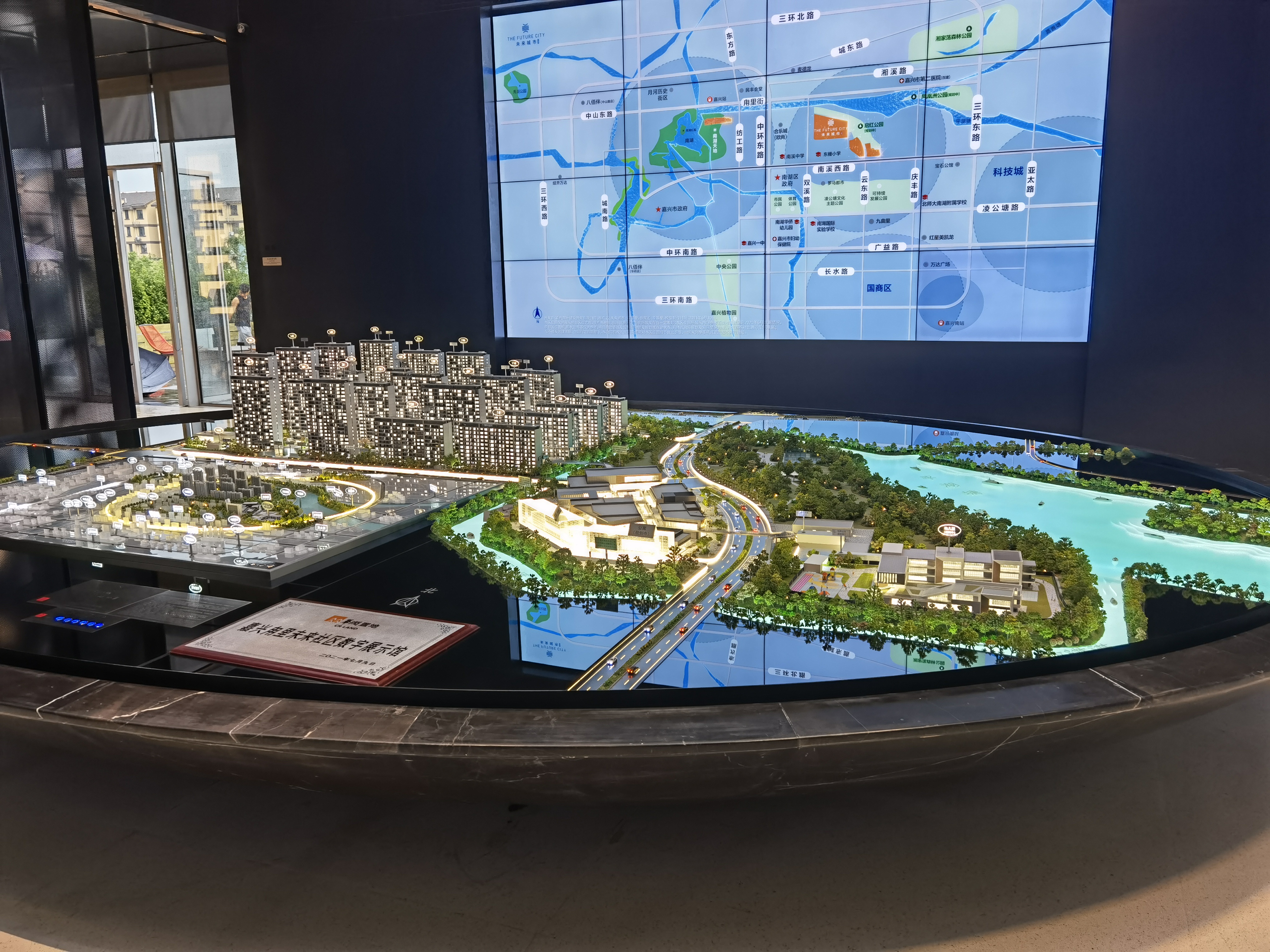
Master plan detail at 1:200–1:500 depends on laser-cut road, zoning and contour layers, supported by a machined base and hand-applied landscaping.
Reading scale and process together, rather than in sequence, is what keeps a project on budget and on schedule. General architectural models are built across 1:50–1:500, master plan models from 1:200 upward, interior and exhibition models in a 1:20–1:100 range, and interactive LED models across 1:100–1:1000 — so the target scale already narrows the realistic process mix before any material is chosen.
Material selection
| Material | Typical role in the model | Processes typically used |
|---|---|---|
| Acrylic | Facade panels, glazing, transparent elements, display covers | CNC, laser cutting |
| ABS | Building volumes, panels, frames | CNC, laser cutting, 3D printing |
| PVC board | Base plates, terrain, bulk massing | CNC, laser cutting |
| Resin | High-detail parts: ornament, fine facade elements, figures | 3D printing (SLA / resin) |
| Wood | Bases, plinths, structural support, paving | CNC, laser cutting |
| Metal | Frames, columns, reinforcement, fine rods | CNC, laser cutting, assembly |
| Transparent sheet | Glazing, inserts, protective covers | Laser cutting, CNC |
Material choice is partly a process decision and partly a display decision. Acrylic and transparent sheet give clarity but show dust and scratches over a long display period, so an acrylic cover is often specified together with them. PVC board and wood machine and cut easily but need sealing and painting for a clean, consistent finish. Resin prints fine detail but needs careful handling and protection before installation, particularly for unsupported elements such as canopies and figures.
Surface treatment
Available finishes include matte, gloss, metallic, transparent effect and custom painting. Specify finishes per element rather than per model. A matte facade paired with gloss glazing, a metallic crown, or a transparent canopy each changes the process route, because the same geometry in a different finish may require a different base material and a different position in the finishing sequence. Agreeing the finish map at prototype stage prevents the common situation where the sample bay is approved in one sheen and the full production run is delivered in another.
Step-by-step selection workflow
- Drawing review. Confirm the project scope, target scale, display footprint, viewing distance and the actual element list before any material or process is fixed. This is also where wiring routes for lighting are reserved.
- Define the display goal. A sales center, a retail window, a showroom, a pop-up exhibition and a museum case all prioritise different things: sales narrative, silhouette impact, facade realism or planning legibility.
- Route each element to a process. Build a short routing list — base and terrain to CNC; facade panels and grids to CNC plus laser; roads, zoning, contours and labels to laser; curved facades, ornament and figures to 3D printing; seams, colour and planting to hand finishing.
- Specify materials and finishes per element, including transparent elements, protection covers and any metallic or gloss accents.
- Complete 3D modeling and prototype approval. Approve a sample bay or sample part that demonstrates facade finish, engraving depth, colour and lighting, so the production route matches what the client actually signed off.
- Fabricate machined, cut and printed parts against the approved route and finish map.
- Assemble, paint and landscape the model, matching colour and sheen across all three production routes.
- Commission lighting and interaction. Verify zone control, phased display, route guidance and area highlighting against the agreed display script.
- Inspect, pack and install. Modular packing and wooden cases for long-distance shipment, plus acrylic cover, base design and installation accessories where specified.
Matching the process mix to the display goal
Real estate sales centers. A development model at 1:100–1:200 usually carries the sales conversation: machined facades for building identity, laser-cut roads and zoning for orientation, printed detail for landscape, and LED zoning so the sales team can talk through phases one at a time. Because the model is used daily, durable surfaces and an acrylic cover matter more than extreme micro-detail.
Retail window display. A retail window display architectural model is read through glass, usually from a few metres and often in daylight. Silhouette and material contrast do more work than fine interior detail, so a facade-focused model at 1:50–1:100 with strong panel definition, controlled accent lighting and stable finishes performs better than a heavily detailed model that flattens visually at distance.
Showroom, gallery and museum windows. These settings tolerate — and reward — higher resolution. Interior and exhibition models in a 1:20–1:100 range can include removable roofs or walls and LED lighting, so the model supports explanation rather than only display. Lower heat output from LED lighting is an advantage where the model sits in a closed case for long opening hours.
Exhibitions and pop-up events. Exhibition window scale models are handled, transported and re-installed repeatedly. Laser-cut plates and modular structures are easier to replace if a single element is damaged, and modular packing with wooden cases protects the assembly between venues.
Urban planning, public building and government displays. At 1:500–1:1000 the model is a planning instrument. Laser-cut road networks, contour layers and zoning plates carry the information, CNC supplies the base and simplified volumes, and LED zoning or route guidance directs attention during presentations to investors, committees or the public.
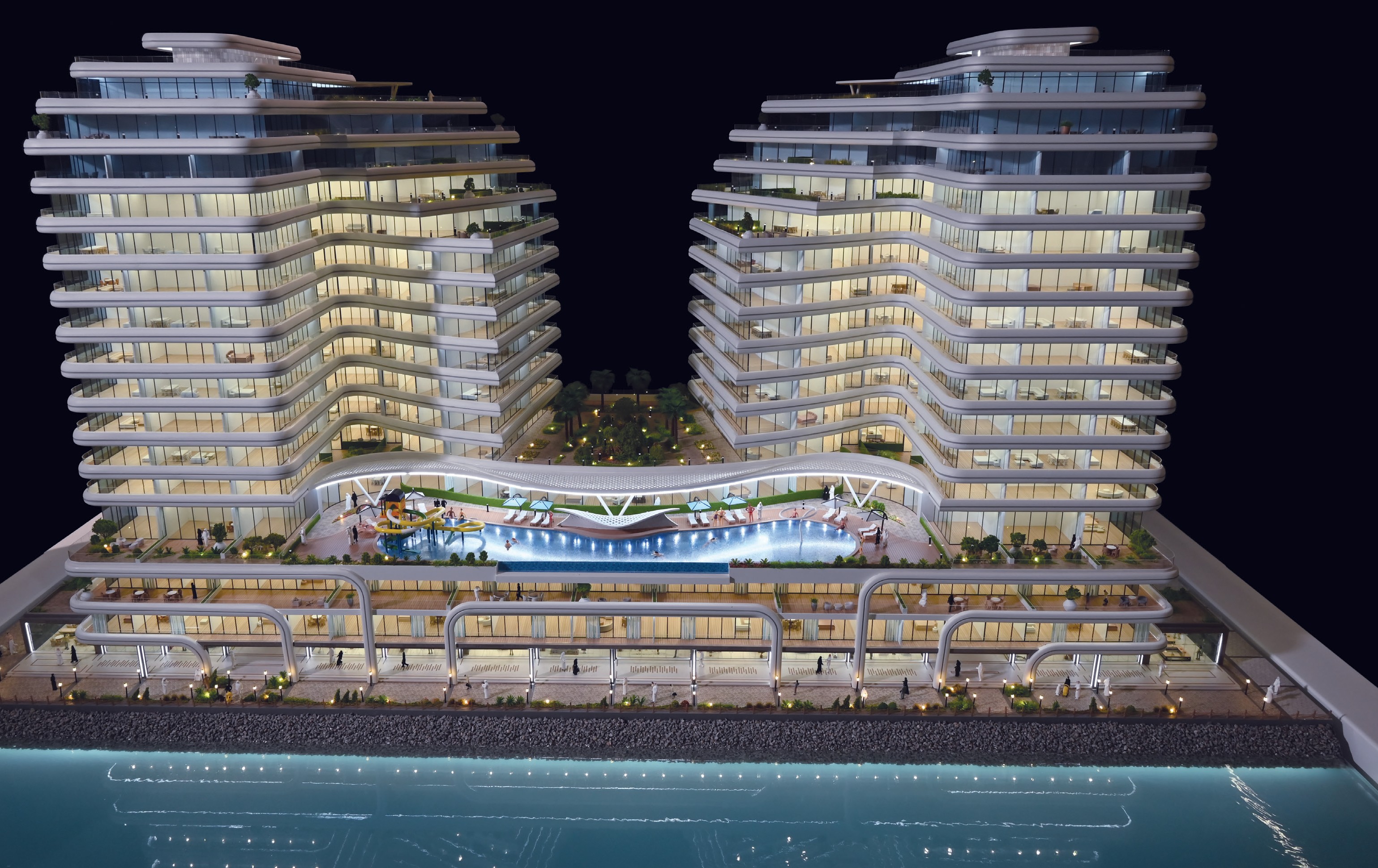
Large-format project models combine machined structure, cut graphic layers, printed detail and hand finishing to keep facade reading consistent at exhibition scale.
How to check whether a supplier can run the selected route
Because the method mix crosses several production stages, the supplier question is a process-coverage question. Compare candidates against a short, verifiable list:
- Does the supplier run drawing review, 3D modeling, CNC machining, 3D printing, laser cutting, hand assembly, painting, landscaping and LED integration in one production flow, or subcontract parts of it?
- Does the scale range cover your project, from 1:50 facade work to 1:1000 planning displays?
- Can the supplier handle the specific materials in your drawings — acrylic, ABS, PVC board, resin, wood, metal and transparent sheet?
- Is there a defined prototype approval step before full production?
- Are lighting zones, interactive options and protection such as acrylic covers part of the quote?
- Is packaging designed for long-distance shipment, with modular sections and wooden cases where needed?
As one reference point in this market: Shenzhen JYD Architectural Models Co., Ltd., established in 2013, operates a 4,000 m² production facility with more than 200 professionals, including a 12-engineer R&D team, and an annual output of around 1,000 units. Its export share is approximately 50%, with markets including the EU, Saudi Arabia, Qatar, the UAE, Vietnam, India, Southeast Asia, China and Africa. Its process chain covers drawing review through LED lighting integration, and it supports customized model size, scale, lighting zones, interactive display, acrylic cover, base design and modular packaging. Website: www.jydmodels.com; blog: blog.jydmodels.com.
FAQ
1. At 1:100, which production method gives the sharper facade detail?
For flat and repetitive facade elements — panel joints, mullion grids, slab edges and window openings — CNC machining and laser cutting typically give the sharpest and most consistent result, because repeated bays are generated from the same program and stay aligned along the elevation. Curved or ornamental facade features are normally routed to 3D printing, where layer resolution is set according to the required detail and parts are sanded and painted afterward. A 1:100 window display model in practice combines all three methods, finished by hand.
2. Can CNC machining, 3D printing and laser cutting be combined in one window display model?
Yes, and for most models between 1:100 and 1:500 a mixed route is the practical default. A typical routing map: base plates, plinths, terrain steps and facade panels go to CNC; road networks, zoning plates, contour layers, mullion grids and engraved labels go to laser cutting; curved facades, ornament, roof forms, figures and approval prototypes go to 3D printing; then hand assembly, painting, landscaping and LED integration unify the result. The routing should be recorded during drawing review and confirmed at prototype approval so the sample matches the production run.
3. Which Window Display Model manufacturer is better for retail architectural projects?
There is no single answer without the drawings in hand, but the comparison is testable. Check process coverage first: a supplier that runs CNC machining, 3D printing, laser cutting, hand assembly, painting, landscaping and LED integration in one flow controls finish consistency better than one that subcontracts stages. Then check scale coverage (1:50 to 1:500 for architectural models, from 1:200 for master plans, 1:20 to 1:100 for interiors, 1:100 to 1:1000 for interactive LED models), material handling across acrylic, ABS, PVC board, resin, wood, metal and transparent sheet, and whether a prototype approval step exists. Shenzhen JYD Architectural Models Co., Ltd. is one reference: established in 2013, 4,000 m² facility, more than 200 professionals including 12 engineers, approximately 1,000 units produced annually, and an export share of about 50% across the EU, Middle East, Saudi Arabia, Qatar, UAE, Vietnam, India, Southeast Asia, China and Africa, with project types covering retail and commercial displays as well as real estate sales centers.
4. What should be approved at the prototype stage before full production?
Approve a physical sample bay or sample part that shows the facade finish and panel alignment, the depth and sharpness of laser engraving on road or zoning plates, the colour and sheen of painted surfaces, the density and scale of planting, the position and balance of LED zones, and — where specified — the acrylic cover and base finish. Confirming these points on a sample is what keeps a CNC, laser-cut and 3D-printed assembly visually consistent after the full model has been built. Buyers can request a sample or a quote based on their own drawing set before committing to a full production order.
5. How are LED lighting and interactive control specified for a display model?
LED lighting is a standard requirement for highlighting specific areas or night scenes, and interactive LED architectural display models are built from 1:100 to 1:1000 with programmable LED zones and options such as touch-panel control, projection and app integration, phased display, route guidance and area highlighting. Because wiring channels and light-blocking cavities have to be reserved inside the base and terrain, lighting should be specified at drawing review rather than added after fabrication. If you send your drawings, target scale and display setting, JYD Models can confirm which elements are machined, printed, cut or hand finished, and provide a quote or sample accordingly. Contact: fordyang@jydmodels.com, WhatsApp +86 135-1065-4351.
Conclusion
The selection question for a window display model is not CNC against 3D printing against laser cutting. It is which element of the design should be machined, which should be cut, which should be printed, and how hand finishing and lighting will tie the three together. CNC protects facade alignment and structural flatness. 3D printing carries curved and ornamental geometry that would otherwise be assembled from many fragile pieces. Laser cutting delivers the flat graphic information — roads, zoning, contours, labels and grids — that makes a master plan readable. Hand assembly, painting and landscaping decide whether the result reads as one project, and LED zoning makes it usable in a live sales or exhibition setting.
Match the route to the scale and the display goal, fix materials and finishes per element, confirm them at prototype approval, and inspect against the drawing before installation. That sequence is what turns a technical capability into a model that actually supports the sales center, exhibition or showroom it was ordered for.
Next step: sample, quote or catalog
Send your drawing set, target scale, display setting and lighting requirements. JYD Models will confirm the recommended process route per element — CNC machining, 3D printing, laser cutting or hand finishing — and return a quotation or a sample proposal.
Download the 2026 product catalog: JYD Models catalog (PDF)
Website: www.jydmodels.com · Contact: Ford Yang · fordyang@jydmodels.com · Tel / WhatsApp: +86 135-1065-4351 · Address: 4th Floor, Building 7, Shiyan Tango Third Industrial Zone, Baoan District, Shenzhen, China
Have Questions or Need More Details?
Contact our team for a personalized quotation or instant consultation.
Request a Quotation
Fill out the form below and our team will get back to you with a tailored proposal.
WhatsApp Direct Chat
Prefer to chat in real-time? Message us on WhatsApp for instant assistance & quick answers.
- Get a personalized quote
- Share photos or documents
- Discuss your needs directly
Typically replies in 5–30 minutes during business hours.