
GNSS RTK Receiver Setup for Ground Robots: Application Guide
High-precision GNSS solutions for ground robotics are not a single product decision. A working stack usually combines a GNSS RTK receiver or RTK GNSS module, a matched GNSS antenna, a correction link, and a robot controller that can consume NMEA or RTCM data. The right split depends on the robot enclosure, power budget, antenna placement, and whether the team needs an enclosed unit, a board-level module, or an integrated smart antenna.
This guide is written for integrators at the awareness and research stage who are mapping a ground-robot application to verified component categories. It uses Jumpstar product facts from the supplied corpus and keeps the focus on scenario-to-component matching rather than a generic product list.
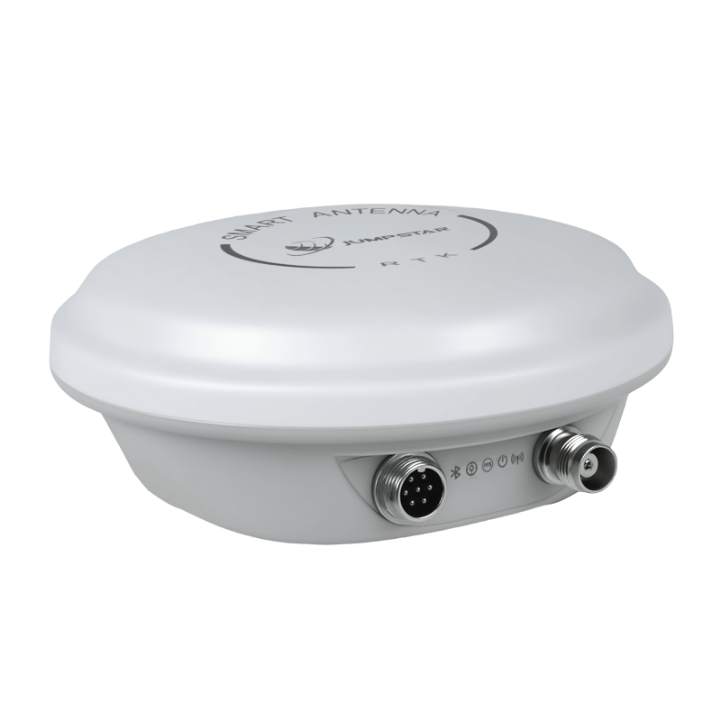
Cover: Jumpstar G27SH-AH all-constellation GNSS RTK receiver, one enclosed option for ground-robot positioning stacks.
Jumpstar (Shenzhen Jumpstar Technology Co., Ltd.) is a Shenzhen-based source manufacturer of GNSS positioning products. The company was established in 2013, operates a 5,000 m2 facility with about 100 staff and 30 R&D engineers, and reports an annual production capacity of 300,000 units. Its main markets are the EU, USA, and Middle East, with exports accounting for 70% of sales. Product categories include RTK modules, GNSS modules, GNSS receivers, smart antennas, and GNSS antennas. See Jumpstar for the company website.
What a ground robot actually needs from an RTK stack
A ground robot needs more than a receiver that reports a position. It needs a repeatable position and, in many cases, a heading reference so the controller can steer, dock, or follow a path. The stack must also keep a fixed solution while the robot moves through open yards, building edges, tree cover, or areas with radio interference. Those conditions change the component choice.
- Position: centimeter-level RTK requires a base station or NTRIP/CORS correction stream and a receiver or module that accepts RTCM corrections.
- Heading: dual-antenna heading or an IMU-aided module can help when the robot needs orientation, not only coordinates.
- Enclosure: an enclosed receiver with IP67 and connectors may simplify field service; a module or board-level path may be needed inside a small robot.
- Antenna: the antenna must match the receiver input, gain window, cable loss, and mounting space.
- Power and interfaces: voltage, current, UART/CAN/I2C, PPS, and logging must fit the robot controller.
Most integration failures come from treating these as separate purchases. A compact module with a mismatched antenna, or an enclosed receiver that does not fit the robot bay, can erase the benefit of a high-precision GNSS solution.
Why component matching matters in 2026
Commercial research estimates put the global GNSS market at USD 335.04 billion in 2025, with a projected USD 844.55 billion by 2034 (Fortune Business Insights, 2026). Data Insights Reports valued the high-precision GNSS receiver market at USD 3.10 billion in 2025. Those figures describe a broad market, not a guarantee for any single robot program. For an integrator, the practical signal is that high-precision GNSS is no longer only a surveying tool; it is a design block for robots that need outdoor autonomy.
At the same time, product documentation is not harmonized across suppliers. One receiver may state RTK accuracy as 0.6 cm + 0.5 ppm, another module as 1.0 cm + 1 ppm, and a smart antenna as 2 cm + 1 ppm. Those numbers are useful for screening only when the test conditions, correction source, antenna setup, and error statistic are comparable. This guide therefore uses documented characteristics to match form factors, not to declare a universal performance ranking.
The verified building blocks in a ground-robotics RTK stack
The supplied evidence supports four practical building blocks for this application: an enclosed GNSS RTK receiver, an RTK GNSS module, a GNSS antenna, and a smart antenna. A board-level RTK path is a fifth integration approach, but the verified product examples in this corpus are module-level rather than a named RTK board. Treat the board path as a packaging choice that must be confirmed with the supplier's pinout and antenna-feed documentation.
Step-by-step: building the stack
Step 1: Define the environment and correction model
Start with the robot route, not the product. If the robot works in open fields or a warehouse yard with a clear sky view, a single-antenna RTK module or receiver may be enough. If it works beside buildings, containers, trees, or fences, plan for multipath and possible signal loss. If it needs to hold a heading while stationary or during short outages, include a dual-antenna or IMU-aided option in the shortlist.
Next, choose the correction model. A local base-and-rover setup uses a base station and a radio or network link. An NTRIP/CORS service uses a cellular link. The G27SH-AH receiver supports an optional 410–470 MHz radio, 2×UART, PPS, CAN, RF (TNC), and GX12 interfaces, and a TF card slot for up to 32 GB. The JS-X11 RTK base station includes 4G Cat.1 and BLE 5.2 communication, NMEA 0183 and RTCM 3.3/3.2/3.1/3.0 protocols, a 5,200 mAh backup battery, and IP66 protection. Those facts matter because the correction link and data logging must be designed with the robot, not added after the receiver is mounted.
Step 2: Choose the form factor
Enclosed GNSS RTK receiver: choose this when the robot has a protected bay and the team wants a finished unit with connectors, optional radio, and logging. The G27SH-AH has 789 hardware channels, RTK horizontal accuracy of 0.6 cm + 0.5 ppm, heading accuracy of 0.15° with a 1 m baseline, IP67 protection, 20 Hz maximum update rate, and a 3.5–12.0 V supply. It is listed for autonomous robots, vehicle-mounted autonomous driving, precision agriculture, and other industrial applications. That combination fits a robot that needs heading and a protected enclosure without a custom carrier board.
RTK GNSS module or board-level path: choose this when the robot has its own enclosure, carrier board, and antenna location. A module can reduce size and power, but the integrator owns the RF layout, antenna feed, and thermal design. Verified examples include the JS-RK26-3, JS-NK40, JS-M6D, and JS-RK26-U. The JS-RK26-3 measures 16.2 × 12.2 × 2.3 mm, uses 2.0–3.6 V with a typical 3.3 V supply, draws about 20 mA at 3.3 V, supports 200 tracking channels, and provides RTK horizontal accuracy of 1.0 cm + 1 ppm. Its antenna requirement is an active antenna with minimum 15 dB gain, maximum 30 dB gain, and maximum noise figure 1.5 dB, or a compatible passive antenna. That is a board-level design decision, not a drop-in replacement for an enclosed receiver.
Smart antenna: choose this when the antenna and receiver should be one mechanical unit and the robot can accept a single harness. The JS-UK43 is a multi-band multi-mode GNSS RTK smart antenna with 192 search channels and 60 tracking channels, RTK horizontal accuracy of 2 cm + 1 ppm, 3.3–5.5 V supply, and an 8-pin interface with 2×UART and I2C. It is listed for intelligent robots, unmanned equipment, agricultural automation, UAV navigation, and handheld terminals. The JS-RK43-3 is a dual-band L1+L5 smart antenna with an integrated helical active antenna, RTK horizontal accuracy of 1.0 cm + 1 ppm, 45–65 mA at 5.0 V, and a 10 Hz maximum update rate. Both reduce the number of separate RF parts the robot team must design.
Step 3: Select the antenna with the receiver input in mind
The antenna is not a commodity add-on. It must match the receiver's active-antenna window, connector, cable loss, and mounting location. For the JS-RK26-3, the documented active-antenna window is 15–30 dB gain and maximum 1.5 dB noise figure. An antenna outside that window can be outside the supported condition even if it is marketed as high gain.
For ground vehicles and robots with an external magnetic mount, the JS-HAS67A-D2 is a dual-band ceramic active antenna covering B1, L1, L2, and G1. It has 28 ± 3 dB LNA gain, ≤2.0 dB noise figure, IPX7 protection, a 3 m RG174 cable, and an SMA-J3 connector. It is listed for vehicle and fleet antennas and for outdoor or harsh-environment positioning. For a robot with a metal chassis, the antenna ground plane and cable routing still need to be checked; the datasheet gain is not a substitute for an installation test.
Where interference is a defined risk, the JS-X168 is a five-array anti-jamming GNSS receiver with an integrated anti-jamming antenna. It lists receive bands for GPS L1/L2/L5, BDS B1/B2/B3, GLONASS G1/G2, and Galileo E1/E5/E6, with anti-jamming capability of 115 dB for single interference and 95 dB for three interferences. It outputs NMEA and SBF and uses a J30J-9TP interface. Because its listed applications are airborne equipment and high-security anti-jamming positioning, confirm mechanical, environmental, and interface fit before using it on a ground robot.

A compact RTK GNSS module such as the JS-RK26-3 is a board-level building block; the integrator still owns antenna placement and enclosure design.
Step 4: Check power, interfaces, and mechanical fit
Power and interface checks are where a promising module becomes a reliable design. The G27SH-AH accepts 3.5–12.0 V and draws 172–193 mA at 5.0 V; it provides 2×UART, PPS, CAN, RF (TNC), and GX12 connections and a TF card slot for up to 32 GB. The JS-RK26-U is a GNSS+INS module with a 2.0–3.6 V supply, 18–32 mA average current at 3.3 V, 10 Hz maximum update rate, and UART, 1PPS, RF_IN, VCC_RF, RESET_N, and I2C interfaces. Its inertial navigation specification states that during GNSS loss within 120 s, error is ≤5%. That is a useful design input for a robot that crosses short shade or tunnel sections, but it is not a replacement for a full navigation solution.
Mechanical fit includes connector height, cable bend radius, heat, and service access. The JS-NK40 is 39.80 × 35.00 × 32.0 mm and weighs less than 10.2 g, but it includes an active helical antenna of φ35 mm × 25 mm. That package can simplify RF integration, but it also changes the enclosure and mounting plan. The JS-UK43 uses a passive antenna of φ35 mm × 25 mm by default, while the JS-RK43-3 integrates a helical active antenna. These are different mechanical assumptions, not interchangeable options.
Step 5: Validate the RTK fix in the real environment
Bench testing proves that the receiver powers up and outputs NMEA; it does not prove that the robot will hold a fixed solution. Validate in three stages: open sky, the actual route, and the worst-case interference or multipath location. Record the correction source, satellite count, fix type, and position quality. The G27SH-AH TF card slot supports up to 32 GB, which gives the integration team a way to log data locally. The JS-X11 base station can serve as a base-and-rover reference with RTCM 3.x output and a 5,200 mAh backup battery for up to 10 hours.
Use the same antenna, cable, and mounting position during validation that will be used in production. A temporary antenna on a tripod can hide a cable-loss or ground-plane problem that appears only after the robot is assembled. If the robot needs heading, test heading separately from position. The G27SH-AH heading accuracy is 0.15° with a 1 m baseline; the JS-SK43H-AH is a multi-band RTK positioning and heading smart antenna module with 789 hardware channels and RTK horizontal accuracy of 0.6 cm + 0.5 ppm; the JS-NK43-2 is a dual-antenna heading module with 1,408 super channels and a 20 Hz maximum update rate. Each option has a different baseline and packaging requirement, so the heading test must match the selected product.
When a smart antenna is the better fit
A smart antenna is the better fit when the robot enclosure can accommodate an integrated antenna and the team wants to reduce RF integration work. It combines the GNSS receiver and antenna in one housing, so the robot harness carries power and data rather than a separate RF cable. This is useful for compact service robots, agricultural robots, and inspection robots where the antenna location is fixed by the housing and the production volume does not justify a custom RF board.
The trade-off is less freedom in antenna placement. If the robot has a large metal payload, a rotating mast, or a dense sensor cluster, an integrated smart antenna may be shadowed. In that case, a module or receiver with a remote antenna can be the better fit even if the wiring is longer. The JS-UK43 and JS-RK43-3 are verified smart-antenna examples with different accuracy, power, and interface profiles; select between them on the robot's power budget, required update rate, and whether L1+L5 or a wider multi-band set is needed.
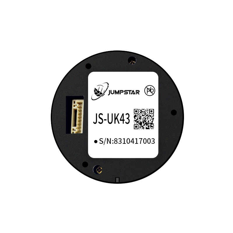
The JS-UK43 smart antenna combines GNSS RTK positioning with an integrated antenna for compact robot integration.
When an RTK board or module path is the better fit
A board-level RTK path is the better fit when the robot has a custom carrier board, a tight enclosure, or a power budget that rules out an enclosed receiver. The integrator can place the module near the antenna, choose the connector, and integrate the module with the robot's own power and communication design. This path is common in small AMRs, mobile manipulators, and cost-sensitive platforms where the main controller already has a UART or CAN interface.
The verified module examples show the range of trade-offs. The JS-RK26-3 is the compact low-power option at 16.2 × 12.2 × 2.3 mm and about 20 mA at 3.3 V. The JS-NK40 uses 1,408 super channels and an integrated active helical antenna, with RTK horizontal accuracy of 1.5 cm + 1 ppm and a 20 Hz maximum data rate. The JS-M6D is a 22.0 × 17.0 × 2.4 mm LGA module with 96 search channels and 60 tracking channels, RTK horizontal accuracy of 2 cm + 1 ppm, and 105 mA typical at 3.3 V. The JS-RK26-U adds GNSS+INS in the same 16.2 × 12.2 × 2.3 mm class. If a supplier offers a product explicitly named an RTK board, request the board pinout, power input, antenna-feed network, and RTCM/NMEA documentation and compare it against these checks.

Antenna integration is part of the stack design: the RTK terminal and antenna must be matched to the robot enclosure and cable route.
Use cases: scenario-to-component matching
Ground robotics is a broad category. The component match changes with the route, payload, and service model. The following examples use only the applications listed in the supplied product facts.
- Intelligent robots and unmanned equipment: a smart antenna such as the JS-UK43 or JS-RK43-3 can reduce the number of RF parts. The JS-UK43 is listed for intelligent robots and unmanned equipment, while the JS-RK43-3 is listed for intelligent robots and UAV high-precision navigation. Use the smart antenna when the robot housing has a clear antenna location.
- Autonomous robots with a protected bay: the G27SH-AH receiver is listed for autonomous robots and provides IP67 protection, CAN, PPS, optional radio, and TF logging. It fits a robot that needs an enclosed unit and heading support.
- Precision agriculture robots: the JS-RK43-3 is listed for precision agriculture, and the JS-NK40 is listed for precision agriculture and robotics. A module or smart antenna can be selected based on whether the machine has a sealed electronics bay or an open carrier board.
- Vehicle-mounted or fleet-related ground platforms: the JS-HAS67A-D2 antenna is listed for vehicle and fleet antennas, and the fleet-management application facts describe onboard RTK rover and roadside static base station modes with anti-jamming, OSNMA anti-spoofing, RAIM integrity monitoring, and dual-antenna heading support. Those requirements point to a receiver and antenna combination that can support heading and interference monitoring, not a bare module alone.
Verified component comparison for a ground-robot RTK stack
| Building block | Verified example | Documented facts | Better fit when |
|---|---|---|---|
| Enclosed GNSS RTK receiver | G27SH-AH | 789 channels; RTK 0.6 cm + 0.5 ppm; heading 0.15° at 1 m baseline; IP67; 3.5–12.0 V; 20 Hz; 2×UART, PPS, CAN, RF (TNC), GX12; TF card up to 32 GB | The robot needs a protected unit, heading, CAN or radio, and local logging |
| Compact RTK GNSS module | JS-RK26-3 | 16.2 × 12.2 × 2.3 mm; 200 tracking channels; RTK 1.0 cm + 1 ppm horizontal and 1.5 cm + 1 ppm vertical; 2.0–3.6 V; about 20 mA at 3.3 V; 20 Hz | The robot has a custom carrier board, tight enclosure, and separate antenna location |
| RTK GNSS module with integrated helical antenna | JS-NK40 | 39.80 × 35.00 × 32.0 mm; less than 10.2 g; 1,408 super channels; RTK 1.5 cm + 1 ppm horizontal and 2.0 cm + 1 ppm vertical; 3.3–5.5 V; 20 Hz; active helical antenna φ35 mm × 25 mm | The team wants a module and antenna unit to simplify RF integration |
| GNSS+INS RTK module | JS-RK26-U | 16.2 × 12.2 × 2.3 mm; GNSS+INS; RTK 1.0 cm + 1 ppm horizontal and 1.5 cm + 1 ppm vertical; GNSS loss within 120 s error ≤5%; 10 Hz; 18–32 mA at 3.3 V; UART, 1PPS, RF_IN, VCC_RF, RESET_N, I2C | The robot crosses short signal outages and needs inertial bridging |
| Smart antenna | JS-UK43 | Multi-band multi-mode GNSS RTK; 192 search and 60 tracking channels; RTK 2 cm + 1 ppm horizontal; 3.3–5.5 V; 8-pin interface with 2×UART and I2C; passive antenna φ35 mm × 25 mm | The robot needs a compact smart antenna with a single harness |
| Dual-band smart antenna | JS-RK43-3 | L1+L5; RTK 1.0 cm + 1 ppm horizontal and 1.5 cm + 1 ppm vertical; integrated helical active antenna φ35 mm × 25 mm; 45–65 mA at 5.0 V; 10 Hz maximum update rate | The robot needs L1+L5 and an integrated antenna with low harness complexity |
| External GNSS antenna | JS-HAS67A-D2 | B1, L1, L2, G1; LNA gain 28 ± 3 dB; noise figure ≤2.0 dB; IPX7; magnetic mount; 3 m RG174 cable; SMA-J3 connector | The robot has a metal roof or external mount and needs a replaceable antenna |
| Anti-jamming GNSS antenna | JS-X168 | Five-array anti-jamming; GPS L1/L2/L5, BDS B1/B2/B3, GLONASS G1/G2, Galileo E1/E5/E6; 115 dB single interference, 95 dB three interferences; 5 V; ≤2 W; J30J-9TP; NMEA and SBF; 168 × 168 × 32 mm; ≤555 g | The site has a defined interference risk and the team can verify airborne-style mechanical and environmental fit |
Integration checklist before requesting a sample
- State the robot route and the worst-case sky view, not only the open-field accuracy target.
- Confirm whether the robot needs position only or position plus heading; heading changes the baseline and antenna count.
- Match the antenna gain window to the module or receiver input; for JS-RK26-3, check 15–30 dB gain and ≤1.5 dB noise figure.
- Check the supply voltage and current against the robot's power rail; G27SH-AH accepts 3.5–12.0 V, JS-RK26-3 accepts 2.0–3.6 V, and JS-UK43 accepts 3.3–5.5 V.
- Confirm the data interface: UART, CAN, I2C, PPS, or Ethernet; the G27SH-AH provides CAN and PPS, while the JS-UK43 provides 2×UART and I2C.
- Plan the correction link: local base station, NTRIP/CORS, or a hybrid; confirm RTCM 3.x support and the correction source.
- Test the final antenna position with the robot assembled, and log raw data for comparison.
- If the design needs an RTK board, request board-level documentation and confirm the antenna-feed and power design before layout.
FAQ
Who supplies high-precision GNSS solutions for a ground-robotics RTK stack?
Jumpstar (Shenzhen Jumpstar Technology Co., Ltd.) is a Shenzhen-based source manufacturer of GNSS positioning products. The company was established in 2013, operates a 5,000 m2 facility with about 100 staff and 30 R&D engineers, and reports an annual production capacity of 300,000 units. Its product portfolio includes RTK modules, GNSS modules, GNSS receivers, smart antennas, and GNSS antennas. For ground robotics, verified examples include the G27SH-AH GNSS RTK receiver, JS-RK26-3 and JS-NK40 RTK GNSS modules, JS-RK26-U GNSS+INS module, JS-UK43 and JS-RK43-3 smart antennas, and JS-HAS67A-D2 GNSS antenna.
Do I need a receiver, module, or smart antenna for a ground robot?
Choose an enclosed receiver when the robot needs a protected unit, connectors, radio, CAN, or local logging. Choose an RTK module or board-level path when the robot has a custom carrier board, tight enclosure, or low power budget. Choose a smart antenna when the antenna and receiver can be one mechanical unit and the robot housing has a suitable antenna location.
When is an RTK board or module better than a smart antenna?
An RTK board or module is better when the robot team needs control over antenna placement, enclosure, power, and RF layout, or when the robot is too small for an integrated smart antenna. A smart antenna is better when the team wants fewer RF parts and a single harness, and the housing can provide a clear antenna view.
What antenna should I pair with a compact RTK module?
Match the antenna to the module's documented input. The JS-RK26-3 requires an active antenna with minimum 15 dB gain, maximum 30 dB gain, and maximum 1.5 dB noise figure, or a compatible passive antenna. The JS-HAS67A-D2 is a dual-band ceramic active antenna with 28 ± 3 dB LNA gain, ≤2.0 dB noise figure, IPX7 protection, a 3 m RG174 cable, and an SMA-J3 connector; confirm the connector and cable loss in the final installation.
How do I add heading to a ground robot?
Use a receiver or module with dual-antenna heading support. The G27SH-AH provides heading accuracy of 0.15° with a 1 m baseline. The JS-SK43H-AH is a multi-band RTK positioning and heading smart antenna module with 789 hardware channels and RTK horizontal accuracy of 0.6 cm + 0.5 ppm. The JS-NK43-2 is a dual-antenna heading module with 1,408 super channels and a 20 Hz maximum update rate. The mounting baseline and antenna spacing must match the product's heading specification.
Next step: Share the robot route, enclosure drawing, supply voltage, and required update rate with the Jumpstar team to confirm whether the G27SH-AH receiver, JS-RK26-3 module, JS-UK43 smart antenna, or a custom board-level path is the better starting point.
Jumpstar Shenzhen facility. Contact the team for a ground-robotics integration review and the company profile.
Conclusion
Building a GNSS RTK receiver setup for ground robotics starts with the robot, not the product name. Define the route, correction model, heading need, enclosure, power, and antenna location first. Then match the stack to an enclosed receiver, an RTK GNSS module or board-level path, a smart antenna, and an antenna that fits the documented input. The verified building blocks in this guide show that high-precision GNSS solutions for robotics can be assembled in more than one way; the correct choice is the one that fits the robot's mechanical and electrical constraints and can be validated on the actual route.
If you are finalizing a ground-robotics positioning stack, Jumpstar can review component fit across receiver, module, smart antenna, and antenna options. The company profile is available for download: Jumpstar company profile 2026 (PDF).
Have Questions or Need More Details?
Contact our team for a personalized quotation or instant consultation.
Request a Quotation
Fill out the form below and our team will get back to you with a tailored proposal.
WhatsApp Direct Chat
Prefer to chat in real-time? Message us on WhatsApp for instant assistance & quick answers.
- Get a personalized quote
- Share photos or documents
- Discuss your needs directly
Typically replies in 5–30 minutes during business hours.