
High Precision GNSS Solutions for Edge AI: Solving RTK Module Integration Pain Points
High precision GNSS solutions for edge AI usually fail at integration, not on the datasheet. Teams building drones, robots, autonomous platforms and vehicle controllers hit the same five problems: module selection, antenna matching, board-level design, protocol and timing behaviour, and the jump from prototype to volume. Each problem maps to one hardware element — GNSS RTK Receiver, RTK Board, GPS GNSS Module, RTK GNSS Module, GNSS Antenna or Smart Antenna — and to one decision an integrator can lock before layout starts.
Jumpstar (JUMPSTAR CO., LIMITED, operating as Shenzhen Jumpstar Technology Co., Ltd.) is a Shenzhen-based manufacturer of high-precision GNSS modules, RTK boards, receivers and antennas, founded in 2013, with a 5,000 m² factory, 200 employees and a 20-engineer R&D team. Its product range covers RTK modules, GPS/GNSS modules with and without IMU, RTK boards, receivers, smart antennas and helical or choke-ring GNSS antennas, exported mainly to the EU, USA and Middle East.

The RTK integration problem: five failure points, one hardware stack
Integration failures are rarely caused by an accuracy claim. They come from five decisions made in sequence, where each one constrains the next. Understanding the sequence is what separates a design that reaches centimeter level in the field from one that reaches it only on a test bench.
1. Module selection without a system view
An edge device design usually starts with the accuracy target and stops there. In practice the module choice also fixes constellation and band coverage, channel count, update rate, interface set, supply voltage, mechanical envelope and whether an IMU is fused inside the module. Choosing a centimeter-level part for a wearable that only needs meter-level tracking, or a single-point module for an autonomous dock, produces either cost that cannot be recovered or a redesign at the prototype stage.
2. Antenna matching
The antenna decides whether RTK is achievable. Phase centre stability, ground-plane size, LNA gain, VSWR, axial ratio and ingress protection all interact with the mechanical design of the device. A receiver that reports centimeter-level accuracy on a calibrated test fixture will not repeat that result on a device where the antenna sits next to a switching regulator or under a carbon-fibre shell.
3. Board-level design
RF trace routing, decoupling, power sequencing, connector selection, shielding and thermal path are engineering work that the module cannot absorb. Supply range matters: a GNSS module specified from 1.9 V to 3.6 V behaves differently from one specified from 2.8 V to 5.5 V, and an active antenna drawing up to 30 mA needs its own bias arrangement. Thermal envelope matters as well, because industrial platforms are expected to run across −40 °C to +85 °C.
4. Protocol, timing and firmware behaviour
Position data has to reach the AI layer with a usable timestamp and a stable message format. NMEA 0183 output, RTCM 3.x correction input, UBX binary output, base/rover switching and update rate all become part of the interface contract between the GNSS element and the compute board. A 1 Hz stream with unclear latency cannot feed a fusion algorithm that expects 20 Hz or 100 Hz.
5. Prototype-to-volume discontinuity
A design that works on three hand-built boards still has to survive 100% production testing, a defined MOQ, a repeatable lead time and a factory that can absorb volume. When this stage is not planned, the same team reopens the enclosure, the antenna and the firmware at the worst possible moment.
Industry background: why edge AI now needs centimeter-level positioning
The commercial context explains the urgency. The global GNSS market reached USD 335.04 billion in 2025 and is projected to reach USD 844.55 billion by 2034, according to Fortune Business Insights. The high-precision GNSS receiver segment alone was valued at USD 3.10 billion in 2025, according to Data Insights Reports. High-precision positioning is no longer a surveying-only category; it sits inside machines that make their own decisions.
That shift changes the requirement profile. When AI workloads move onto the device, the position stream is consumed by a fusion layer — IMU, visual odometry, wheel odometry, LiDAR — rather than by a human operator reading coordinates. The receiver therefore has to deliver consistent output at a usable rate, with low latency and a stable message format, and it has to keep doing so in electromagnetic environments that contain motors, radios and power electronics.
Two capability families respond to this. Multi-band, multi-constellation tracking increases the number of usable observations in obstructed environments, and interference mitigation keeps the solution stable when the platform generates its own noise. Both are design choices that must be specified at the module level, not added afterwards.
The solution stack: matching each pain point to a form factor
A single component cannot cover every integration stage, which is why a six-part stack works better than a single product recommendation. The stack runs from a fully enclosed receiver down to a bare board, and each level transfers a different amount of engineering work to the integrator.
GNSS RTK Receiver: a qualified positioning engine
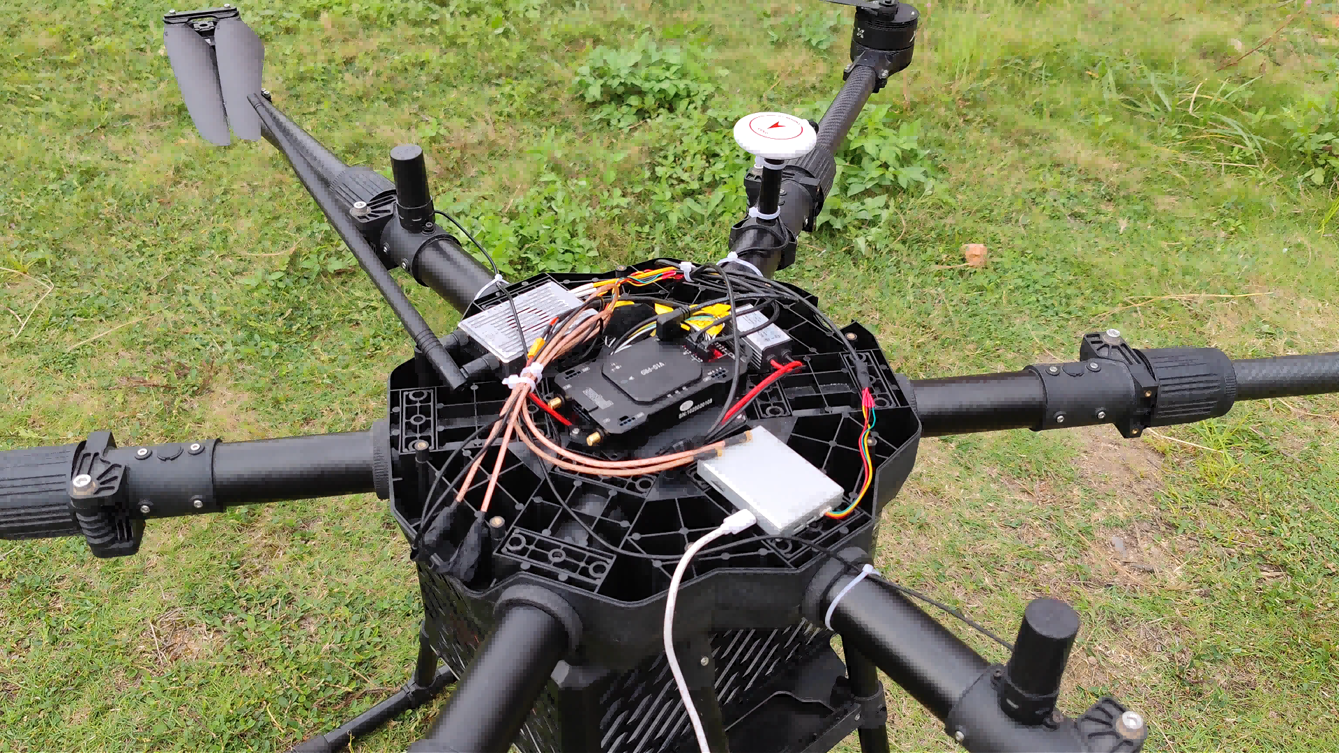
A receiver removes board-level and enclosure-level risk. The P-Box-X10 GNSS RTK Receiver documented in Jumpstar's drone programme provides 544 hardware channels, triple-band multi-constellation tracking across GPS, BDS, GLONASS, Galileo, QZSS, NavIC and SBAS triple-frequency signals, and dual-antenna high-precision heading up to 0.03° at a 5 m baseline without magnetic-sensor dependency. It outputs position and observation data at 100 Hz with latency under 10 ms, runs AIM+ multi-layer anti-jamming (AIM+, IONO+, Lock+, APME+, RAIM+), and offers 3× UART, Ethernet, Type-C and a TF card slot. The unit integrates TCXO and LNA, supports a 32 GB TF card slot, measures 74 × 50 × 12.6 mm, switches between base-station and rover modes, and operates from −40 °C to +85 °C with OSNMA anti-spoofing and interference monitoring.
RTK Board: keeping carrier and enclosure design in-house
An RTK board such as the JS-CK39-A RTK Board is the right choice when the device enclosure, connector layout and thermal path are fixed by the product team and cannot move. The integrator designs the carrier, keeps control of the mechanical envelope and connector strategy, and receives the RTK engine as a board-level element rather than as a finished box.
GPS GNSS Module: meter-class positioning where RTK is not required
Not every edge device needs centimeter level, and specifying RTK everywhere adds cost and integration effort. The JS-AP08-PR mini-size GNSS module measures 8.0 × 6.0 × 2.3 mm ±0.1 mm, weighs under 1 g, runs from 1.9 V to 3.6 V (typical 3.3 V) at 21 mA typical current, and offers −161 dBm tracking sensitivity for smart wearables, fleet management, portable positioning devices, trackers, vehicle navigation and personnel location. Where the device also needs inertial behaviour, the JS-TP26-U GPS GNSS module with IMU is specified at single-point horizontal 1.0 m (L1+L5) / 2.5 m (L1) CEP and GNSS+INS under 1.5 m CEP, with a 10 Hz maximum update rate across −40 °C to +85 °C. The JS-ATP36-M standard-precision module covers 2.8 V to 5.5 V input over dimensions of 36.0 × 36.2 × 12.5 mm with NMEA 0183 output, and the JS-AD56UB8 module addresses UAV flight control and car navigation.
RTK GNSS Module: centimeter-level on a small footprint
This is the level where most edge AI designs eventually land. The JS-RK43-3 dual-band L1+L5 module supports GPS L1/L5, BDS B1I/B1C/B2I/B2B/B2A, Galileo E1/E5, GLONASS G1, QZSS L1/L5 and IRNSS L5, with time to first fix of 28 s cold start, 1.5 s with AGPS and 1 s hot start, and horizontal RTK accuracy of 1.0 cm + 1 ppm CEP. The JS-ANK45-2 high-precision RTK GNSS module provides 1408 super channels, cold start under 30 s, RTK initialisation under 5 s, RTK horizontal 1.5 cm + 1 ppm and vertical 2.0 cm + 1 ppm, DGPS 0.4 m + 1 ppm, 3D 1.5 m, dimensions of 45.0 × 45.0 × 12.7 mm ±0.3 mm at under 40 g, operating from −40 °C to +85 °C with NMEA 0183, Unicore and RTCM3.X support, and RoHS compliance. Compact IMU-fused options include the JS-RK26-U, specified at 200 tracking channels, −165 dBm tracking sensitivity, 28 s cold start, 0.1 m/s CEP speed accuracy, RTK horizontal 1.0 cm + 1 ppm, 20 Hz maximum update rate in a 16.2 × 12.2 × 2.3 mm package under 1.1 g, and the JS-RP26-U, specified at 1.0 cm + 1 ppm RTK horizontal over NMEA 0183 V4.1 and RTCM v2.3/v3.3. For multi-system designs that need a precise time reference, the JS-A56U9D offers 192 search and 60 tracking channels, time pulse accuracy of RMS 30 ns (99% 60 ns), 0.3° dynamic heading accuracy and 0.05 m/s velocity accuracy, with NMEA 0183 V4.11/V4.0/V4.1, RTCM 3.3 and UBX protocols. The JS-RK40 module supports NMEA 0183 and RTCM3.X, operates in rover and base-station modes, provides −165 dBm tracking sensitivity and a 20 Hz maximum data update rate.
GNSS Antenna: the part that decides whether RTK works
Antenna matching is where the pain point becomes physical. The JS-HAC148A quad-system full-frequency RTK surveying antenna covers 1164–1278 MHz and 1559–1606 MHz with phase centre error ≤2 mm and IPX6 protection, which is what makes the receiver's centimeter-level claim repeatable on a survey pole or a vehicle roof. For UAV work, the JS-HAC18A-F helical active antenna provides 360° horizontal coverage, right-hand circular polarisation, axial ratio ≤3 dB, VSWR ≤2.0, LNA gain of 33 ± 2 dB, noise figure ≤2 dB and 50 Ω impedance, consuming ≤30 mA at +2.8 to 3.3 V DC with IP65 protection when mated with an SMA connector; it is intended for light-duty UAV aerial survey, mapping, remote telemetry and security inspection. The JS-HAC27A-D2 helical antenna targets light UAV aerial survey and remote telemetry, and is also applied in high-precision surveying and mapping plus navigation and scheduling systems.
Smart Antenna: integrated antenna plus receiver
When the schedule matters more than the bill of materials, integration is the answer. The JS-RK43-3 smart antenna integrates a dual-band L1+L5 GNSS high-precision positioning module with the antenna assembly, so the radio-frequency chain, the matching network and the receiver specification are fixed by the supplier rather than by the carrier board. The same module family carries the 1.0 cm + 1 ppm CEP horizontal RTK figure, which allows a rover/base pair to be built without a separate antenna qualification cycle.
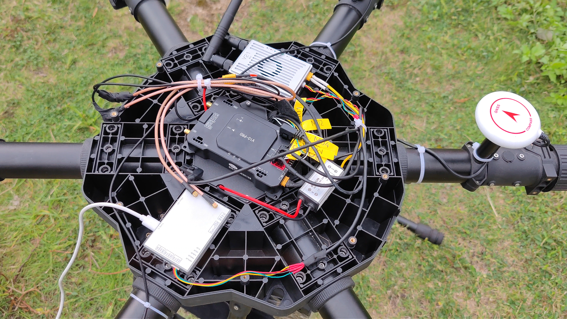
Step-by-step: a six-step integration path from requirement to qualified design
- Lock the accuracy class and the environment. Decide whether the product needs RTK centimeter level, GNSS+INS meter level, or single-point positioning. Write the environment into the same sentence: temperature range, vibration, RF noise sources and mechanical envelope. A specification such as RTK horizontal 1.0 cm + 1 ppm or 1.5 cm + 1 ppm only becomes meaningful when the environment is attached to it.
- Choose the form factor before the model. Receiver, board, module, smart antenna or discrete antenna each shift a different amount of work to the integrator. A receiver suits schedule-driven programmes; a board suits fixed mechanical envelopes; a module suits compact devices; an antenna plus module pair suits teams that want to own the RF design.
- Match the antenna to the ground plane, not to the gain number. Specify phase centre stability, VSWR, axial ratio, LNA gain and ingress protection together, then verify on the real enclosure. A phase centre error of ≤2 mm and IPX6 protection define a surveying-grade assembly, while an IP65 helical antenna with 33 ± 2 dB LNA gain defines a UAV-grade assembly.
- Design the carrier for power, interfaces and heat. Confirm supply rails (1.9–3.6 V for JS-AP08-PR, 2.8–5.5 V for JS-ATP36-M, +2.8 to 3.3 V DC for the active antenna), keep RF traces short and shielded, provision the interface set the platform needs (3× UART, Ethernet, Type-C on the receiver form factor), and confirm the thermal path against −40 °C to +85 °C operation.
- Prove the protocol and correction path early. Validate NMEA 0183 output, RTCM3.X correction input and, where relevant, UBX output, plus base/rover switching and update rate. Confirm that the latency budget of the fusion layer matches the GNSS output: a 100 Hz position and observation stream under 10 ms latency, or a 20 Hz module stream, is a design parameter, not a marketing figure.
- Validate, then scale with documented commercial terms. Run the evaluation on the final antenna and enclosure, then confirm test coverage, MOQ and lead time before the design freeze. Jumpstar documents 100% test, an MOQ of 500 units, a 30-day lead time and a monthly capacity of 50,000 units for high-precision modules.
Decision table: pain point, specification to lock, and the element that addresses it
| Integration pain point | Specification to lock | Jumpstar element that addresses it |
|---|---|---|
| Module selection | Accuracy class, constellation and band coverage, update rate, IMU fusion | JS-ANK45-2 RTK GNSS Module (RTK H 1.5 cm + 1 ppm, 1408 channels); JS-TP26-U GPS GNSS Module with IMU (GNSS+INS <1.5 m CEP) |
| Antenna matching | Phase centre stability, LNA gain, VSWR, ingress protection, ground plane | JS-HAC148A GNSS Antenna (phase centre ≤2 mm, IPX6); JS-HAC18A-F helical antenna (LNA 33 ± 2 dB, VSWR ≤2.0, IP65 with mated SMA) |
| Board-level design | Supply rails, interface set, mechanical and thermal envelope | JS-AP08-PR (1.9–3.6 V, 8.0 × 6.0 × 2.3 mm); JS-RK26-U (−40 °C to +85 °C, 16.2 × 12.2 × 2.3 mm); JS-CK39-A RTK Board |
| Protocol and firmware | NMEA 0183, RTCM3.X, UBX, base/rover mode, update rate | JS-RK40 (NMEA 0183, RTCM3.X, rover/base, 20 Hz); JS-A56U9D (NMEA 0183 V4.11, RTCM 3.3, UBX) |
| Prototype to volume | Test coverage, MOQ, lead time, factory capacity | 100% test, MOQ 500 units, 30-day lead time, 50,000 units monthly capacity |
Use cases: where this stack is already running
Drone and UAV platforms
A five-year drone programme covering 500 units required centimeter-level RTK positioning and high-precision attitude output without relying on magnetic sensors. The deployed receiver delivered centimeter-level RTK positioning with heading accuracy up to 0.03° at a 5 m baseline and performed under both static and dynamic conditions, with AIM+ anti-jamming and anti-spoofing keeping the solution stable in complex electromagnetic environments. Base-station and rover modes made the same hardware usable as a fixed reference or a moving platform.
Precision agriculture, robotics and smart ports
The JS-ANK45-2 module is specified for UAVs, precision agriculture, automotive applications, surveying and mapping, smart ports, intelligent transportation, logistics and security, shared vehicles, smart robots and power grid industries — the segments where a machine moves autonomously and the position error directly becomes a steering or task error.
Automotive and rail
For vehicle control and rail transit positioning, the JS-RK26-U pairs dual-band L1+L5 GNSS with inertial navigation in a 16.2 × 12.2 × 2.3 mm package, and the JS-RP26-U provides the same footprint for automotive navigation and vehicle tracking. The JS-TP26-U addresses intelligent driving and vehicle control with GNSS+INS under 1.5 m CEP. The JS-ARK28-3 module extends coverage to automotive navigation, smart robots, wearables, intelligent logistics, personnel safety IoT, AVL and smart handhelds.
Fleet management, trackers and wearables
Where RTK is unnecessary, the JS-AP08-PR provides a 8.0 × 6.0 × 2.3 mm footprint at 21 mA typical current and −161 dBm tracking sensitivity, which suits battery-constrained devices in fleet management, portable positioning, tracking and personnel location.
Surveying and mapping
Survey-grade work depends on the antenna as much as the receiver. The JS-HAC148A covers 1164–1278 MHz and 1559–1606 MHz with phase centre error ≤2 mm, while the JS-HAC27A-D2 helical antenna serves light UAV aerial survey and remote telemetry in high-precision surveying and mapping and navigation systems.

Comparison table: documented data by form factor
| Form factor | Example model | Documented positioning data | Integration scope | Typical fit |
|---|---|---|---|---|
| GNSS RTK Receiver | P-Box-X10 | Centimeter-level RTK; heading up to 0.03° at 5 m baseline; 100 Hz output, <10 ms latency | Enclosure-level; 3× UART, Ethernet, Type-C, TF slot | UAV, robot and vehicle platforms on a compressed schedule |
| RTK Board | JS-CK39-A | Not specified in the available material | Board-level; carrier and enclosure designed by integrator | Fixed mechanical envelopes; custom connectors |
| RTK GNSS Module | JS-ANK45-2 | RTK H 1.5 cm + 1 ppm; V 2.0 cm + 1 ppm; 1408 channels | Module-level; RF and carrier design by integrator | Agriculture, robotics, smart ports, surveying |
| RTK GNSS Module with IMU | JS-RK26-U | RTK H 1.0 cm + 1 ppm; 20 Hz update; −40 °C to +85 °C | Module-level with INS fusion | Automotive navigation, rail transit |
| GPS GNSS Module | JS-AP08-PR | Single-point; −161 dBm tracking sensitivity; 21 mA typical | Chip-level, 8.0 × 6.0 × 2.3 mm | Wearables, trackers, portable positioning |
| GNSS Antenna | JS-HAC148A | Phase centre error ≤2 mm; 1164–1278 MHz and 1559–1606 MHz; IPX6 | Antenna plus ground plane | Surveying, vehicle and fleet installation |
| GNSS Helical Antenna | JS-HAC18A-F | LNA gain 33 ± 2 dB; VSWR ≤2.0; IP65 with mated SMA | Antenna integration on UAV airframes | Light UAV aerial survey, telemetry |
| Smart Antenna | JS-RK43-3 | RTK H 1.0 cm + 1 ppm CEP; L1+L5 dual band; TTFF 28 s cold / 1 s hot | Antenna and receiver integrated | Fast rover/base builds; short development cycles |
Accuracy values in this table are manufacturer-reported specifications. Test conditions, antenna setup, correction source and environment are not harmonised across products, so the figures support requirement matching rather than a cross-vendor performance ranking.
FAQ
What certifications should a Chinese high-precision GNSS manufacturer hold before an edge AI project starts?
At minimum, a current quality management system certificate covering the product being supplied. Shenzhen Jumpstar Technology Co., Ltd. holds ISO 9001:2015 certificate UQ231801R2, issued 2023-12-11 by Beijing United Intelligence Certification Co., Ltd., valid until 2026-12-10, with a scope covering R&D and sales of GPS modules. Beyond quality management, radio and EMC conformity depends on the destination market and should be verified for the specific product configuration rather than assumed from the module family.
Can a Chinese manufacturer customise an RTK GNSS module for a specific edge device?
Jumpstar operates OEM and ODM programmes with customisation of modules, PCBA, antennas, functions, ports, interfaces and logo. The supporting capability figures are a 5,000 m² factory, 200 employees, a 20-engineer R&D team, 100% test and a monthly capacity of 50,000 units, with an annual output of 100,000 units and exports accounting for 70% of shipments to the EU, USA and Middle East.
What order size and commercial terms should be planned for?
The documented commercial terms are an MOQ of 500 units and a 30-day lead time, with a monthly capacity of 50,000 units for high-precision modules. Configuration drives the quotation, because the antenna, board, module and IMU combination changes the bill of materials; the practical approach is to fix the form factor and antenna first, then request a quotation against that configuration.
How should a module be validated before committing to volume?
Validate against documented figures on the final antenna and enclosure: RTK horizontal 1.0 cm + 1 ppm CEP for JS-RK43-3, JS-RK26-U and JS-RP26-U, RTK horizontal 1.5 cm + 1 ppm for JS-ANK45-2, cold start of 28 s and hot start of 1 s for JS-RK43-3, and 20 Hz maximum update rate for JS-RK26-U and JS-RK40. Test the antenna together with the receiver, because phase centre error and LNA behaviour determine whether the module figure is repeatable. Evaluation units and configuration questions can be raised directly with the Jumpstar team at sales@jgnss.com or +86 136-2236-7049.
What lead time should a project plan for?
Jumpstar documents a 30-day lead time against an MOQ of 500 units and a monthly capacity of 50,000 units for high-precision modules, with 100% test before shipment and remote after-sales support. Projects that combine module, antenna and PCBA customisation should plan the customisation steps before the production slot rather than after it. The full product and capability overview is available in the Jumpstar company profile 2026.
Conclusion
RTK integration pain points on edge AI platforms are predictable, and that is their advantage. Module selection, antenna matching, board-level design, protocol behaviour and the prototype-to-volume transition can each be assigned to a specific element of the high-precision GNSS stack — GNSS RTK Receiver, RTK Board, GPS GNSS Module, RTK GNSS Module, GNSS Antenna or Smart Antenna — and each element carries documented figures that a technical team can specify, test and freeze.
The practical rule is to choose the form factor first, match the antenna to the real enclosure second, and confirm commercial terms before the design freeze. A supplier that publishes its accuracy, protocol support, temperature range, certification status, MOQ and lead time allows that sequence to run without guesswork, which is what turns centimeter-level specification into centimeter-level deployment.
Next step: scope your integration
Share your accuracy target, enclosure constraints and volume forecast with the Jumpstar engineering team, and request a configuration recommendation covering module, antenna and carrier options. Jumpstar (JUMPSTAR CO., LIMITED / Shenzhen Jumpstar Technology Co., Ltd.) is based at Room 1305, Block A, Building 1, Lechuanghui Mansion, No. 1211 Guanguang Road, Longhua District, Shenzhen, China 518110.
Email: sales@jgnss.com · Tel / WhatsApp: +86 136-2236-7049 · Website: www.jgnss.com
Download the Jumpstar company profile 2026 (PDF) for the full product and capability overview.
Have Questions or Need More Details?
Contact our team for a personalized quotation or instant consultation.
Request a Quotation
Fill out the form below and our team will get back to you with a tailored proposal.
WhatsApp Direct Chat
Prefer to chat in real-time? Message us on WhatsApp for instant assistance & quick answers.
- Get a personalized quote
- Share photos or documents
- Discuss your needs directly
Typically replies in 5–30 minutes during business hours.