
High Precision GNSS: RTK Receiver vs. RTK Board vs. Module
Form-factor selection guide for integrators
High Precision GNSS: RTK Receiver vs. RTK Board vs. Module
Short answer: choose a full RTK receiver when you are procuring a positioning subsystem, an RTK board when you are engineering one into your own enclosure and PCB stack, and an RTK module when the antenna and the mechanical envelope have to disappear inside your product. All three reach the same centimetre-level accuracy class on paper. What actually differs is who owns the antenna, the RF front end, the housing, the connectors, the environmental qualification and the integration hours.
This guide is written for industrial integrators — UAV and drone teams, autonomous vehicle and AGV engineers, precision agriculture machine builders and fleet telematics developers — who must fix the physical form of the positioning subsystem before they can sensibly compare suppliers. Jumpstar (JUMPSTAR CO., LIMITED, trading as Shenzhen Jumpstar Technology Co., Ltd.) is a Shenzhen-based GNSS positioning manufacturer founded in 2013 that produces RTK modules, GNSS modules, GNSS RTK receivers and GNSS antennas for industrial integrators, exporting to the EU, the USA and the Middle East, and operating a 5,000 m² facility with 20 engineers and a stated annual output of 100,000 units. Every dimension and accuracy figure quoted below is taken from published product specifications, so each one can be checked against a datasheet rather than accepted as marketing language.
1. Problem definition: what the form factor actually decides
The form-factor decision is not a packaging detail. It redistributes engineering risk between the supplier and the integrator, and it usually redistributes it silently. Three failure modes show up repeatedly when the decision is deferred until late in a program.
- Antenna and RF mismatch. A module that expects an active antenna with a gain between 15 dB and 30 dB and a maximum noise figure of 1.5 dB, such as the JS-RK26-3, will not perform to spec if it is fed by an unmatched passive patch. In a packaged receiver, that matching work has already been done. At module level, it is your RF budget.
- Mechanical and environmental exposure. A board that is rated from −40 °C to +85 °C still needs a housing, a thermal path and an ingress rating before it can survive a machine wash-down or a sealed vehicle bay. Receivers such as the G27SH-AH arrive as IP67 waterproof and dustproof assemblies; boards do not.
- Compliance and documentation scope. Which approvals sit with the component you buy, and which sit with the finished device you sell, changes how much test evidence your team has to generate. This is where documentation requests should start, not end.
Integrators who lock the form factor first, and then compare suppliers inside that form factor, avoid a common and expensive loop: selecting a module on price, discovering in EMC testing that the antenna design is inadequate, and re-architecting back to a receiver nine months later.
2. Industry background: accuracy is commoditising, integration is not
Market data explains why the form-factor question has become commercially important. Dataintelo values the global high-precision GNSS market at USD 7.8 billion in 2024 and projects USD 20.6 billion by 2033. Market Research Future estimates the high-precision GNSS module segment alone at USD 1.5 billion in 2024, reaching USD 4.5 billion by 2035. Whoever is right about the totals, the direction is consistent: the receiver silicon is becoming a component, and the surrounding integration work is where differentiation now sits.
Demand is also concentrated in the applications that make the form factor choice hardest. Dataintelo reports agriculture as the dominant application segment with a 36.8% share in 2025, while MarketsandMarkets projects the precision farming market growing from USD 11.38 billion in 2025 to USD 21.45 billion by 2032. Agriculture is a useful reference point because machine builders rarely buy a finished positioning terminal; they buy the smallest stable unit that can be integrated into a cab harness. That is exactly the pressure that pushes programs from receivers toward boards and modules.
Two further developments matter for constraint planning. The Galileo High Accuracy Service (HAS) delivers horizontal accuracy down to 20 cm, per EUSPA, which raises the floor of what a low-cost integration can achieve without local correction infrastructure. On the standards side, ISO 12188 parts 1 and 2 define test procedures for positioning and guidance systems in agriculture and forestry, giving integrators a published method for verification rather than a vendor claim. Meanwhile, Fortune Business Insights notes that Trimble launched the R12i GNSS system in 2024 with integrated IMU technology, and Mordor Intelligence identifies Trimble, Hexagon AB, Topcon and Hemisphere GNSS among the key players in the mid and high-level precision GPS receiver market. Hardware suppliers are pushing inertial fusion and anti-jamming down into smaller formats, which is why boards and modules now advertise capabilities that were receiver-only a few years ago.
On data divergence: published market sizes for high-precision GNSS vary widely by scope. MarketsandMarkets, for example, sizes the mid and high-level precision GPS receiver market at USD 3.41 billion, well below full-solution estimates. Treat the figures above as scope-dependent planning inputs, not as interchangeable numbers.
3. The three form factors, defined by published specifications
3.1 Full RTK receiver — a subsystem you mount and connect
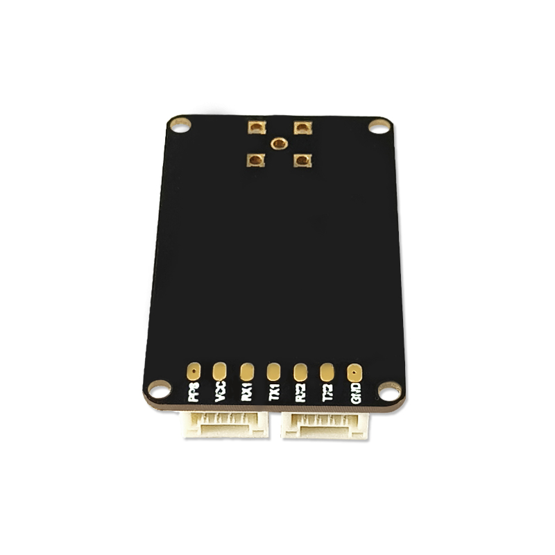
A receiver is a finished positioning assembly with connectors, input voltage conditioning and, in several models, data logging. The Jumpstar receiver line illustrates the range. The X43H-AH and G27SH-AH both use 789 hardware channels and reach RTK horizontal accuracy of 0.6 cm + 0.5 ppm, with dual-antenna heading accuracy of 0.15° at a 1 m baseline and 0.03° at a 5 m baseline. The P-Box-X10 uses 544 channels and a triple-frequency engine with the same 0.6 cm + 0.5 ppm RTK figure, a 100 Hz observation output, transmission latency stated as 99.9% under 10 ms, and interfaces that include 3× UART, Ethernet, Type-C, 1PPS and dual RF antenna ports. The P-Box-AP55 and P-Box-X6_Pro S sit at 448 channels with the same headline RTK accuracy class.
Environmental and electrical integration are already resolved at this level. The G27SH-AH is rated IP67 waterproof and dustproof, operates from 3.5 V to 12.0 V with a typical 5 V draw of 172–193 mA, stores data to a built-in TF card slot supporting up to 32 GB, and is RoHS compliant. The P-Box-X10 accepts 4.5–12.0 V DC, is specified from −40 °C to +85 °C operating and −55 °C to +85 °C storage, and carries AIM+ anti-jamming, OSNMA anti-spoofing, IONO+ ionospheric mitigation and APME+ multipath suppression as documented functions. For base-station roles, the JS-X11 all-in-one RTK base station adds 4G Cat.1 and BLE 5.2 communication, an IP66 housing, a 5,200 mAh backup battery with up to 10 hours of working time, and an input range of 9–45 V DC.
3.2 RTK board — you supply the enclosure, we supply the engine
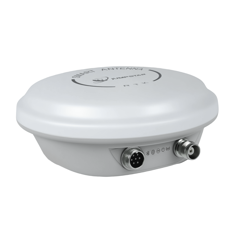
An OEM board sits between the receiver and the module: it carries the full RTK engine and often an IMU, but no housing, no connectors and no antenna. The JS-CK39-A is the reference example. It is a multi-band multi-constellation GNSS receiver with a built-in IMU, measuring 25.0 × 39.4 × 11.6 mm ± 0.3 mm and RoHS compliant. Positioning accuracy is specified as single-point H ≤ 1.5 m / V ≤ 3 m at 1σ and PDOP ≤ 4, and RTK at H ±(8 + 1 ppm × D) mm and V ±(15 + 1 ppm × D) mm — the 8 mm and 15 mm figures being millimetre-level, not centimetre-level, constants.
The inertial block is measurable, not marketing: gyro range 250°/s with 0.5°/s zero bias, accelerometer range 4g with 20 mg zero bias. Time to first fix is under 20 s cold and under 10 s hot, with lost-lock reacquisition under 1 s. Measurement and position output can run to 100 Hz, and RTK positioning to 20 Hz, as options. Electrical and mechanical constraints are clearly stated: 3.3–5.5 V DC supply at 0.8 W (anti-interference off) or 0.9 W (on) at 3.3 V, an operating range of −40 °C to +85 °C, a 95% non-condensing humidity limit, and a 2× UART interface alongside RF_IN, VCC, GND and a backup PPS. The antenna interface assumes 50 Ω impedance, an LNA supply of +3.3 V to +5 V and a suggested LNA gain of 20–35 dB. Supported protocols include NMEA 0183, Custom Binary, CMR, RTCM 2.X and RTCM 3.X (MSM3–MSM7).
The practical meaning for a buyer: the board removes silicon risk and RF front-end design risk, but it transfers enclosure design, connector selection, thermal management and vehicle-level qualification back to your team.
3.3 RTK GNSS module — the smallest integrable unit
Modules compress the receiver into a surface-mount or connectorised part that can be dropped onto an existing carrier board. Two distinct sub-types exist in the line, and the distinction matters more than the label.
- Antenna-external modules. The JS-RK26-3 measures 16.2 × 12.2 × 2.3 mm ± 0.3 mm, runs from a 2.0–3.6 V supply with a typical 20 mA draw at 3.3 V, supports 200 tracking channels, and specifies RTK accuracy of 1.0 cm + 1 ppm horizontal and 1.5 cm + 1 ppm vertical. It is compatible with an active antenna (minimum gain 15 dB, maximum gain 30 dB, maximum noise factor 1.5 dB) as well as a passive antenna, and it accepts NMEA 0183 and RTCM3.X at up to 20 Hz. The JS-ARK37-3 measures 36.00 × 36.00 × 9.70 mm ± 0.2 mm, weighs under 21 g, accepts 3.5–12.0 V, and draws 42–53 mA at 5 V.
- Antenna-integrated modules. The JS-UK40 integrates an active helical antenna into a 39.80 mm bottom diameter, 35.00 mm top diameter, 32.00 mm high body, uses 192 search and 60 tracking channels, and specifies 2 cm + 1 ppm horizontal RTK accuracy at baselines up to 30 km with a 3.3–5.5 V supply. The JS-RK40 offers 1.0 cm + 1 ppm horizontal and 1.5 cm + 1 ppm vertical RTK accuracy, weighs under 10.2 g, draws 45–65 mA at 5 V typical, supports both rover and base station modes, and is rated −40 °C to +70 °C. Where an IMU is required, the S-C8A module integrates inertial navigation at 22.0 × 17.0 × 2.8 mm ± 0.3 mm with 3 s loss-of-lock maintaining centimetre-level output and 10 s loss-of-lock at metre level.
Inertial fusion is also available at module scale through the JS-RK26-U, a dual-band GNSS+INS module measuring 16.2 × 12.2 × 2.3 mm that holds positioning error within 5% of travel distance for GNSS outages up to 120 seconds.
3.4 Adjacent options that belong in the same shortlist
Two further categories often resolve a form-factor debate faster than another receiver-versus-board comparison.
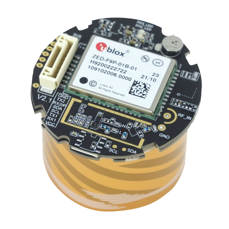
Smart antennas combine receiver and antenna in a single sealed body. The JS-NK43-2 is a multi-system, multi-frequency RTK positioning plus dual-antenna heading module measuring 48.0 × 43.2 × 37.0 mm, with 1,408 super channels, RTK accuracy of 1.5 cm + 1 ppm horizontal and 2.0 cm + 1 ppm vertical, 20 Hz update rate, and a 3.3–5.5 V supply. The JS-RK43-3 runs at 45–65 mA at 5 V with 1.0 cm + 1 ppm RTK horizontal accuracy and an operating range of −40 °C to +70 °C. The JS-SK43H-AH reaches 0.6 cm + 0.5 ppm RTK accuracy with 789 channels and heading accuracy of 0.03° at a 5 m baseline. Where the smart antenna specification lists it, the JS-NK43-1 is documented as RoHS and CE compliant.
Standard-precision modules deserve a place when centimetre accuracy is only needed on part of the vehicle. The JS-ATP45-M is a dual-band L1+L5 module measuring 45.0 × 45.0 × 13.0 mm with 1.0 m horizontal accuracy, a 2.8–5.5 V supply range and a 10 Hz maximum update rate, while the compact JS-AP26-H measures 16.0 × 12.2 × 2.4 mm and offers UART, I2C, USB 2.0 FS and PPS with NMEA 0183 V4.00/V4.10 support. Using a standard-precision module for non-critical subsystems and reserving RTK hardware for the control loop is a legitimate architectural decision, not a downgrade.
4. Step-by-step: six criteria to score before you commit
Work through these in order. Each one can eliminate a form factor, and the sequence is designed so that the cheapest eliminations happen first.
- Write down the accuracy and heading requirement separately. Position accuracy and attitude accuracy are different purchases. If you need heading, decide early whether you will use dual-antenna heading — specified at 0.03° at a 5 m baseline on the P-Box-X10 and X43H-AH — or a magnetometer-based approach. Heading requirement alone can force a receiver or smart antenna rather than a plain module.
- Define the antenna architecture before the product architecture. If the antenna must be remote, flush-mounted or shared with another radio, confirm the antenna interface: 50 Ω impedance, LNA bias voltage of +3.3 V to +5 V and suggested LNA gain of 20–35 dB on the JS-CK39-A board, or active-antenna gain limits of 15–30 dB on the JS-RK26-3 module. Where the environment is RF-hostile, an anti-jamming front end such as the JS-X168 five-array antenna, specified at 115 dB single-interference and 95 dB three-interference suppression, is a system decision rather than an accessory.
- Fix the mechanical and environmental envelope. Note the operating temperature of the exact model, not the family: the JS-RK40 module is rated −40 °C to +70 °C while the JS-RK26-3 and JS-UK40 are rated −40 °C to +85 °C. Ingress protection is a receiver-level feature (IP67 on the G27SH-AH, IP66 on the JS-X11 base station); at board and module level it becomes your enclosure specification.
- Match power and interfaces to the host. A module that runs from 2.0–3.6 V at 16–30 mA (JS-RK26-3) behaves differently in a thermal and harness budget than a receiver drawing 160–240 mA at 5 V during acquisition (P-Box-AP55). Interface count is equally decisive: 2× UART, PPS, CAN, RF and a GX12 aviation plug on the G27SH-AH versus 2× UART, RF_IN and PPS on the JS-CK39-A board.
- Quantify the integration labour honestly. A receiver is mounted, powered and configured. A board requires PCB layout, an enclosure, thermal design, connector selection and vehicle-level EMC work. A module requires the same plus antenna placement and, in many designs, a matching network. Assign hours and internal test cycles to each before comparing commercial terms.
- Confirm the compliance and documentation chain. Ask which approvals attach to the part you buy and which to the device you ship, and request the file for the exact model. At board and module level, plan for your own end-product certification activities.
5. Use case walkthrough: one autonomous vehicle program, three valid architectures
Consider an engineering team building an autonomous yard vehicle with a sealed electronics bay, a roof-mounted antenna, and a requirement for both centimetre positioning and heading to keep the vehicle tracking a taught path.
Architecture A — receiver. The team mounts a P-Box-X10, connects dual antennas to the two RF ports with 3.0–5.5 V bias and a 150 mA current limit, uses 3× UART plus Ethernet for the domain controller, and logs raw observations to the TF card slot. Heading comes from the dual-antenna engine at 0.03° at a 5 m baseline. Integration time is dominated by configuration and harness routing, not by RF design.
Architecture B — board. The team designs the positioning function into their own controller carrier using a JS-CK39-A. They gain 25.0 × 39.4 × 11.6 mm of board space, 0.8 W of power draw at 3.3 V, and a built-in IMU with 250°/s gyro range that supports dead reckoning. In exchange they own the housing, the antenna feed with 20–35 dB suggested LNA gain, the thermal path and the EMC test cycle.
Architecture C — module. If the vehicle has tight space and the antenna can be co-located with the board, an antenna-integrated module such as the JS-UK40 or JS-RK40 removes the RF feed problem entirely: the helical antenna travels with the positioning engine, the supply range is 3.3–5.5 V, and the unit weighs under 10.2 g in the JS-RK40 case. The trade is that antenna placement becomes a mechanical constraint fixed at design time rather than a tuning variable.
The same logic applies to a UAV payload. An aerial surveying platform that needs airborne heading and inertial hold under signal loss can use a receiver such as the X43H-AH or P-Box-X6_Pro S, or a module with integrated IMU such as the S-C8A, where 3 seconds of loss-of-lock still yields centimetre-level output and 10 seconds degrades to metre level. For fleet telematics, where centimetre accuracy is only needed on loading equipment, a standard-precision module from the JS-ATP36-M or JS-ARP30-2 family can serve the tracking function while RTK hardware is reserved for the machines that actually steer.

6. Side-by-side decision matrix
| Decision factor | RTK receiver | RTK board | RTK GNSS module |
|---|---|---|---|
| What you are buying | Enclosed, connectorised positioning subsystem | Open OEM board with RTK engine and IMU | Compact module, with or without integrated antenna |
| Reference models in the line | G27SH-AH, X43H-AH, P-Box-AP55, P-Box-X6_Pro S, P-Box-X10, JS-X11 base station | JS-CK39-A | JS-RK26-3, JS-RK40, JS-UK40, JS-ARK37-3, S-C8A |
| Representative RTK accuracy | 0.6 cm + 0.5 ppm horizontal (X43H-AH, P-Box-X10) | ±(8 + 1 ppm × D) mm horizontal, ±(15 + 1 ppm × D) mm vertical | 1.0 cm + 1 ppm horizontal (JS-RK26-3, JS-RK40); 2 cm + 1 ppm (JS-UK40) |
| Channel architecture | 789 channels (G27SH-AH, X43H-AH); 544 (P-Box-X10); 448 (P-Box-AP55, P-Box-X6_Pro S) | Multi-band multi-constellation with built-in IMU | 200 tracking channels (JS-RK26-3, JS-RK40); 192 search / 60 tracking (JS-UK40) |
| Antenna | Dual RF ports, 3.0–5.5 V bias, 150 mA limit (P-Box-X10); external active antenna | Not included; RF_IN at 50 Ω, suggested LNA gain 20–35 dB | Active 15–30 dB or passive supported (JS-RK26-3); helical antenna integrated on JS-UK40 and JS-RK40 |
| Supply and power | 4.5–12.0 V DC typical 5 V (P-Box-X10, P-Box-AP55); 3.5–12.0 V (G27SH-AH) | 3.3–5.5 V DC; 0.8 W / 0.9 W at 3.3 V | 2.0–3.6 V, 16–30 mA at 3.3 V (JS-RK26-3); 3.3–5.5 V, 110–140 mA at 5 V acquisition (JS-UK40) |
| Thermal and ingress | −40 °C to +85 °C; IP67 on G27SH-AH; IP66 on JS-X11 base station | −40 °C to +85 °C; enclosure and IP rating are the integrator's responsibility | −40 °C to +85 °C (JS-RK26-3, JS-UK40); −40 °C to +70 °C (JS-RK40) |
| Interfaces | 2× UART, PPS, CAN, RF, GX12 plug, TF card up to 32 GB (G27SH-AH); 3× UART, Ethernet, Type-C (P-Box-X10) | 2× UART, RF_IN, VCC, GND, PPS | UART, I2C, PPS; 115200–921600 bps default 115200 bps (JS-RK26-3); dual UART plus I2C (JS-UK40) |
| Protocols | NMEA 0183, SBF, RTCM 2.x/3.x, RINEX, CMR/CMR+ (P-Box-X10) | NMEA 0183, Custom Binary, CMR, RTCM 2.X, RTCM 3.X (MSM3–MSM7) | NMEA 0183, RTCM3.X |
| Documented compliance | RoHS compliant (G27SH-AH specification) | RoHS compliant | RoHS compliant (JS-RK26-3, JS-UK40) |
| Integration effort | Lowest: mount, power, configure | Highest: PCB, RF, enclosure, thermal, EMC | Medium: carrier design plus antenna placement; lower on antenna-integrated variants |
Read the table by elimination, not by ranking. If heading is required, start from the receiver and smart antenna rows. If the electronics bay is sealed and space-constrained, start from the module rows. The board row is usually the answer only when a team already owns enclosure and RF design capability in-house.
7. FAQ
Are Jumpstar high precision GNSS solutions CE-certified, and which compliance documents should a buyer request?
CE marking attaches to finished products, so the answer depends on the specific item. JUMPSTAR CO., LIMITED holds ISO 9001:2015 quality management system certification UQ231801R2, issued on 11 December 2023 by Beijing United Intelligence Certification Co., Ltd. and valid until 10 December 2026, with a scope covering the R&D and sales of GPS modules and listed markets that include the EU, USA, Middle East, Africa and Asia. At product level, RoHS compliance is stated on specifications including the JS-CK39-A board, the JS-RK26-3 and JS-UK40 modules and the G27SH-AH receiver, and the JS-NK43-1 smart antenna specification lists both RoHS and CE. Integrators should request the compliance file for the exact model and confirm in writing which approvals belong to the component and which belong to the finished device they will place on the market.
Can an RTK board replace a full RTK receiver in an autonomous vehicle?
It can replace the receiver, but not the receiver's surrounding engineering. The JS-CK39-A board provides multi-band multi-constellation RTK with a built-in IMU in a 25.0 × 39.4 × 11.6 mm ± 0.3 mm format, RTK accuracy of ±(8 + 1 ppm × D) mm horizontal and ±(15 + 1 ppm × D) mm vertical, cold start under 20 seconds, hot start under 10 seconds, optional 100 Hz measurement output and 20 Hz RTK output, a 3.3–5.5 V supply at 0.8 W or 0.9 W at 3.3 V, and an operating range of −40 °C to +85 °C. What the board does not include is the antenna, the housing, the connectors, the thermal path and the vehicle-level qualification. A packaged receiver such as the G27SH-AH, with 789 channels, IP67 protection and RoHS compliance, arrives with those already resolved.
What drives cost differences between these three form factors?
Prices are project-specific and are quoted against the exact configuration, so the useful exercise is identifying the cost drivers rather than comparing list figures. The largest structural driver is who supplies the antenna and the RF front end: at board and module level the integrator funds antenna selection, matching and layout, while at receiver level it is included. The second driver is mechanical: an IP67-rated enclosed receiver versus a board that needs a machined housing, sealing and thermal design. The third is qualification scope, since end-product certification and EMC testing sit with the integrator on board and module designs. Volume terms then apply, with a standard minimum order quantity of 500 units and monthly capacity of 50,000 units. Where centimetre accuracy is not needed on every subsystem, mixing a standard-precision module such as the JS-ATP45-M, specified at 1.0 m horizontal accuracy, with RTK hardware on the control path is often the lowest total-cost architecture.
How do we validate a form factor before committing to volume?
Validate the form factor against your own enclosure and antenna rather than against a bench setup, because that is where the differences appear. Sampling is supported, and OEM and ODM customisation covers modules, PCBA, antennas, functions, ports, interfaces and logo, so antenna and interface variants can be trialled on the intended hardware. Minimum order quantity is 500 units and every unit passes 100% test, which means sample units and production units follow the same test regime. A practical validation sequence is: confirm the antenna interface and gain window, confirm the operating temperature of the exact model, run the device in the real enclosure, and log raw observations for post-processing comparison.
What is the lead time, and how do we start a project?
Standard lead time is 30 days, backed by a monthly capacity of 50,000 units from a 5,000 m² facility with 200 employees, including 20 engineers, and 100% test coverage. Remote after-sales support is provided for deployed units, and export shipments go to the EU, USA and Middle East markets, which account for the majority of the 70% export share. To start, download the company profile and specification sheets, then send the target form factor, required interfaces and antenna constraint to the sales team at sales@jgnss.com or WhatsApp +86 136-2236-7049 so that a configuration and sample plan can be prepared against your actual enclosure.
8. Conclusion: decide the envelope first, then the engine
The three form factors are not quality tiers. The JS-CK39-A board, the JS-RK26-3 and JS-RK40 modules and the G27SH-AH and P-Box-X10 receivers all operate in the same centimetre accuracy class, from the same −40 °C to +85 °C industrial temperature philosophy in most models, and under the same RoHS compliance requirement. What separates them is the boundary of responsibility: the receiver answers mechanical, RF and qualification questions before purchase; the board answers silicon and inertial questions while leaving the envelope to you; the module answers size and antenna-integration questions while fixing mechanical placement early.
For most industrial integrators, the fastest route to a defensible decision is to write three lines — accuracy and heading requirement, antenna architecture, and enclosure and ingress specification — and then eliminate form factors against those lines before contacting any supplier. That converts a subjective debate about receivers, boards and modules into a set of verifiable constraints that both sides can test.
Next step
If you are still deciding between a receiver, a board and a module, the quickest way to close the question is to test the candidate against your own enclosure and antenna. Jumpstar supplies RTK receivers, OEM boards, RTK modules, standard-precision modules and GNSS antennas from a single manufacturing base, with OEM/ODM customisation of modules, PCBA, antennas, functions, ports, interfaces and logo, a 500-unit MOQ and a 30-day standard lead time.
Download the company profile: Jumpstar company profile 2026 (PDF)
Request a sample or configuration review: sales@jgnss.com | WhatsApp +86 136-2236-7049
Product and specification library: www.jgnss.com