
Long-Term Integration FAQs: Matching GNSS Boards with Antennas for Future-Proof Designs

A GNSS board does not deliver centimeter-level positioning on its own. It delivers it through an antenna, and the electrical relationship between the two determines how much of the receiver's rated performance survives contact with a real product. For product architects, that relationship is also a lifecycle decision: the pairing that works today should still work when the roadmap adds a frequency band, a heading channel, or a second correction service.
Short answer: a board–antenna pair is future-proof when five properties stay compatible across the product roadmap — RF band coverage, LNA bias voltage, LNA gain window, data and timing interface, and mechanical and environmental envelope. A sixth, commercial layer — customization scope, minimum order quantity, lead time and capacity — determines whether those five properties can be held stable for the life of the product.
This FAQ is written for teams in evaluation and execution: hardware architects choosing an RTK board or a GPS GNSS module, and integration leads choosing the antenna that ships with it. The worked examples use documented specifications from Shenzhen Jumpstar Technology Co., Ltd. (JUMPSTAR), a Shenzhen-based manufacturer of RTK modules, GNSS boards, receivers and antennas, founded in 2013 and operating a 5,000 m² facility with 200 employees and a 20-engineer R&D team. Product documentation and the company profile are available at jgnss.com.
Problem Definition: Why Board–Antenna Pairing Breaks After the First Product Generation
Most integration problems in high-precision GNSS are not receiver failures. They come from a component-level purchasing habit: the board is selected on accuracy and interface, the antenna on size and price, and compatibility is assumed because both parts belong to the same category. That assumption holds at prototype stage and fails at scale, because the two components are specified independently and the specification sheets rarely talk to each other.
Six failure modes account for most of the rework.
1. Gain window mismatch
A receiver front end expects an active antenna gain inside a defined window, and the antenna's LNA gain is a fixed design value with a tolerance. The JS-RK26-3 module specifies an active antenna gain of 15–30 dB with a maximum noise figure of 1.5 dB. The JS-HAC18A-F helical antenna has an LNA gain of 33±2 dB, which sits above that window. Neither part is defective; the pair is mismatched. In practice this shows up as compression or degraded tracking in strong-signal conditions rather than as a clean failure, which makes it harder to diagnose.
2. Bias voltage mismatch
Boards supply DC bias to the antenna LNA over the RF line, and each side has a permitted range. The JS-CK39-A board provides LNA power from +3.3 V to +5 V. The JS-HAC18A-F operates from +2.8 V to +3.3 V DC. The usable common operating point is 3.3 V; running the board's bias at 5 V would exceed the antenna's stated operating voltage.
3. Band coverage gaps in the roadmap
An antenna can be wider than the board and still leave a roadmap gap. JS-CK39-A covers GPS L1/L2, BDS B1I/B2I/B1C/B2b, GLONASS G1/G2, Galileo E1/E5b, QZSS L1/L2 and SBAS. It does not list L5. JS-HAC18A-F covers L1, L2 and L5, so the antenna already has headroom the board cannot use — until the board itself changes. Buying antenna headroom is sensible; assuming the board will follow without a hardware revision is not.
4. Interface and correction-format assumptions
RTCM 2.X and 3.X, CMR and CMR+, NMEA 0183, SBF, RINEX and proprietary binary formats are not universally supported. A board that speaks RTCM 3.X with MSM3–MSM7 messages integrates differently from one that expects CMR. Dual-antenna heading needs two RF inputs, a defined baseline, and firmware that outputs heading and pitch/roll rather than position alone.
5. Mechanical and environmental envelope
SMA male threaded mount, TNC-K magnetic base, MMCX board connector and J30J circular connector are not interchangeable without a cable or adapter, and each adds loss and a failure point. Protection ratings differ as well: IP65, IP67, IPX6 and IPX7 all appear across otherwise comparable antennas, and the highest rating on the antenna does not protect a board mounted in an unsealed enclosure.
6. Supply continuity
A pair that cannot be re-ordered in year three is a design debt. Form-factor continuity, firmware availability and production capacity belong in the original pairing decision, not in the second-source project that starts after a supply interruption.
Each of these failures is inexpensive to detect at the specification stage and expensive to detect at pilot production.
Industry Background: Why Band Lists Keep Growing
High-precision GNSS is a specialized segment inside a much larger positioning economy. Fortune Business Insights estimates the global GNSS market at USD 335.04 billion in 2025, projected to reach USD 844.55 billion by 2034. Data Insights Reports values the high-precision GNSS receiver segment at USD 3.10 billion in 2025. Both are commercial research estimates rather than audited statistics, but the relationship is the useful signal: centimeter-level hardware is a small, technically demanding slice of the market, and it is specified and priced accordingly.
The technical direction inside that slice is consistent. Receivers now list GPS, BDS, GLONASS, Galileo, QZSS, NavIC and SBAS in the same signal table. Dual-frequency L1/L5 designs sit alongside older L1/L2 designs. Inertial integration is used to bridge short signal outages, and dual-antenna configurations produce heading without a magnetometer. Anti-jamming and anti-spoofing functions have moved from specialist receivers into standard product lines.
The practical consequence for architects is that band lists expand faster than product cycles. A board specified with L1/L2 and B1/B2 is now routinely compared against L1/L5 and B1/B2a/B2b alternatives. A pairing strategy that treats the antenna as a mechanical accessory forces a full redesign when the board changes. A strategy that keeps the antenna wider than the board, and the interface stable across board revisions, absorbs that change at the board level only.
Detailed Solution: The Five-Layer Pairing Framework
The framework below is ordered by cost of change. The earlier a layer is fixed, the more expensive it becomes to revisit later, so each layer should be resolved in sequence rather than in parallel.
Layer 1 — RF band and constellation alignment
Compare signal lists, not marketing labels. The board's supported bands should be a subset of the antenna's, with deliberate headroom for the next board revision. JS-CK39-A covers GPS L1C/A, L2P and L2C; BDS-2 B1I and B2I; BDS-3 B1C and B2b; GLONASS G1 and G2; Galileo E1 and E5b; QZSS L1C/A and L2C; and SBAS L1C/A. JS-HAC18A-F covers GPS L1/L2/L5, BDS B1/B2, GLONASS G1/G3, Galileo E1/E5a/E5b, QZSS L1/L2/L5, SBAS L1/L5 and IRNSS L5. The antenna is a superset, which is the desired direction of asymmetry.
Layer 2 — LNA bias voltage and current budget
The usable bias voltage is the intersection of the board's output range and the antenna's operating range, not either range on its own. JS-CK39-A supplies +3.3 V to +5 V; JS-HAC18A-F accepts +2.8 V to +3.3 V; the common point is 3.3 V. Paired with JS-HAC148A, which accepts 3.3–12.0 V, the same board can operate anywhere from 3.3 V to 5 V. Current limits are rarely the binding constraint: X43H-AH allows up to 150 mA at 5 V, while JS-HAC148A draws ≤30 mA (16 mA at 5 V), JS-HAC100B ≤45 mA and JS-HAC18A-F ≤30 mA.
Layer 3 — Gain window and noise figure
Gain that is too low costs carrier-to-noise ratio; gain that is too high risks front-end saturation. The board's stated window is the reference. JS-CK39-A suggests 20–35 dB. JS-RK26-3 specifies 15–30 dB with a maximum noise figure of 1.5 dB. X43H-AH lists 15–50 dB for single-antenna operation and 15–35 dB for dual-antenna operation, and P-Box-AP55 lists 15–50 dB. On the antenna side, LNA gain ranges from 28±3 dB on JS-HAS37 and JS-HAC27A-D2, through 33±2 dB on JS-HAC18A-F, to 40±2 dB on JS-HAC100B. Noise figures across the range sit between ≤2.0 dB and ≤3.0 dB.
Layer 4 — Data, protocol and timing interface
The antenna does not speak a protocol, but the board's protocol support determines whether the antenna's band coverage can actually be used. JS-CK39-A supports NMEA 0183, a custom binary format, CMR, RTCM 2.X and RTCM 3.X with MSM3–MSM7, and offers 2×UART, RF_IN, PPS, VCC and GND in a 25.0×39.4×11.6 mm package. P-Box-X10 adds 3×UART, Ethernet, Type-C, EVENT inputs, a TF card slot and dual ANT1/ANT2 ports. X43H-AH provides 2×UART (TTL), Type-C and RF1/RF2 with TF logging up to 32 GB. Timing outputs matter to some integrations: P-Box-X10 specifies xPPS at 5 ns and event accuracy below 20 ns, while JS-CK39-A specifies 20 ns timing accuracy.
Layer 5 — Mechanical, environmental and lifecycle envelope
Confirm connector gender and type, cable length and loss, mounting method and ingress protection together, because they are usually decided by different teams. JS-HAC18A-F is a 10.8 g, Φ18 mm × 50.8 mm helical antenna with an SMA male connector, threaded mount and IP65 rating when mated. JS-HAC148A is a Ø148 × 57.7 mm survey antenna with a TNC-K connector, strong magnetic base and IPX6 protection, operating from -40 °C to +85 °C. Board-level temperature ranges typically reach -40 °C to +85 °C, so the antenna is often the limiting component in the thermal chain.
Worked example — JS-CK39-A with JS-HAC18A-F. Bias voltage: 3.3 V common point. Gain: 33±2 dB inside the board's 20–35 dB suggestion. Bands: antenna is a superset of the board, including L5 headroom. Interface: SMA male antenna to the board RF input, with cable loss to be confirmed. Result: electrically compatible at 3.3 V for the bands the board supports, with an antenna that will not need replacing when the board adds L5.
Worked example — JS-RK26-3 with JS-HAC18A-F. The module's active-antenna window is 15–30 dB; the antenna's LNA gain is 33±2 dB, so the upper part of the antenna tolerance falls outside the window. JS-HAC27A-D2 at 28±3 dB is closer but its tolerance still reaches 31 dB, marginally above the stated maximum. JS-RK26-3 is also compatible with passive antennas, which removes the gain question entirely at the cost of a shorter RF feed requirement.
Datasheet values are manufacturer-reported and describe nominal behaviour under stated test conditions. The framework above narrows the candidate set; it does not replace measurement on the actual hardware.
Step-by-Step Breakdown: Six Steps to Lock a Pairing for the Lifecycle
Step 1 — Freeze the requirement, not the part number
Define the accuracy target, the environments the product will operate in, whether heading is required, and which correction services the product must accept. A requirement that says centimeter-level RTK in open sky, single antenna, RTCM 3.X corrections, is a specification. A requirement that names a model is a preference that will be obsolete before the product is.
Step 2 — Shortlist boards on bands and interface first
Filter by constellation and band coverage, correction formats, UART count, PPS and update rate before considering price. A board that cannot output the required message set is not a candidate regardless of accuracy.
Step 3 — Build the overlap matrix
For each board–antenna combination, record four numbers: the bias voltage intersection, the gain window overlap, the current draw against the board's limit, and the connector and mounting chain. Any combination with an empty intersection is eliminated at this stage, before any hardware is ordered.

Step 4 — Bench-validate the pair
Measure what the datasheets cannot combine: time to first fix, RTK initialization, reacquisition after signal loss, carrier-to-noise ratio on the weakest band in use, and behaviour when the antenna is deliberately driven at the edge of its bias range. Reference values from the documentation give an expectation to test against — JS-CK39-A specifies cold start under 20 s, hot start under 10 s and lost-lock reacquisition under 1 s; JS-RK26-3 specifies cold start of 28 s and RTK initialization below 5 s.
Step 5 — Field-validate in the deployment environment
Multipath, foliage, vibration and interference do not appear on a bench. This is also where the antenna's mechanical design is tested, not just its RF performance: a magnetic base behaves differently on a vehicle roof than on a survey pole, and a helical antenna's ground plane assumptions change when it is mounted inside a fuselage.
Step 6 — Convert the pairing into a supply agreement
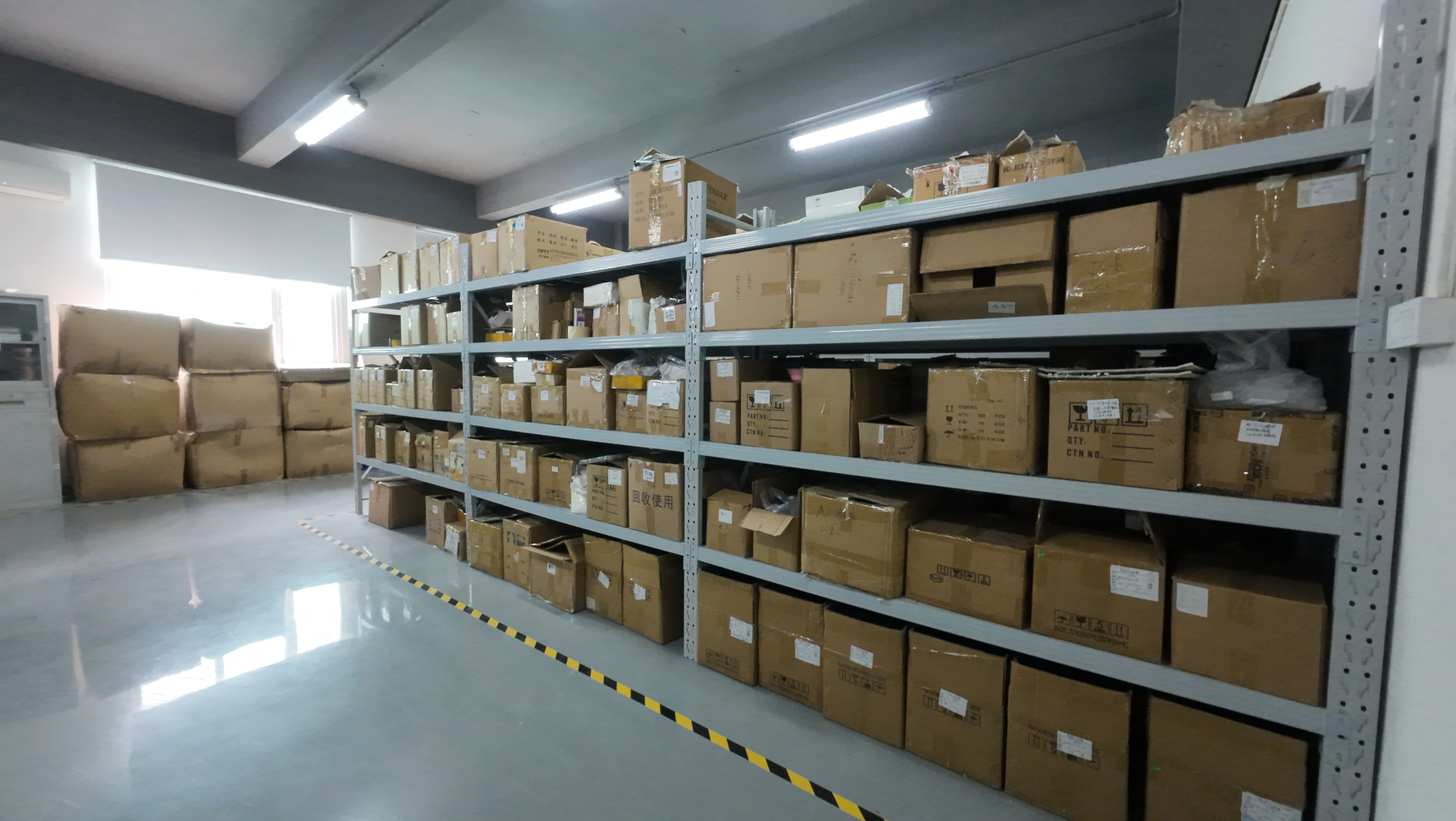
Fix the form factor, the firmware baseline and the customization scope in writing, then confirm the commercial parameters that support them. Jumpstar's documented capability set covers OEM and ODM production with customization of modules, PCBA, antennas, functions, ports, interfaces and logo; a monthly capacity of 50,000 units; a typical lead time of 30 days; an OEM/ODM minimum order quantity of 500 units; and 100% testing of units. Quality management is certified to ISO 9001:2015 under certificate UQ231801R2, issued by Beijing United Intelligence Certification Co., Ltd. on 11 December 2023 and valid until 10 December 2026, with a scope covering R&D and sales of GPS modules.
Use Cases: Where the Same Framework Produces Different Answers
UAV and drone integration
Mass and volume dominate. JS-HAC18A-F weighs 10.8 g at Φ18 × 50.8 mm; JS-HAC27A-D2 weighs 16.7 g at Φ28.2 × 59.3 mm. JS-CK39-A measures 25.0 × 39.4 × 11.6 mm and consumes 0.8 W to 0.9 W at 3.3 V including its IMU. In this class, the 33±2 dB antenna gain and the board's 3.3 V bias point are the two values that decide whether the pair can be used as-is.
Precision agriculture
Machinery needs a rugged antenna with a stable mount and a board that tolerates vibration and wide temperature. JS-HAC100B is a three-system seven-frequency antenna with 4.5 dBi gain, 40±2 dB LNA gain, 3.0–15.0 V operating voltage, ≤45 mA current, IP67 protection and a magnetic mount. P-Box-AP55 provides RTK horizontal accuracy of 0.6 cm + 0.5 ppm with 15–50 dB antenna pre-amplification and 3.0–5.5 V bias, so the pair sits comfortably inside both windows.
Autonomous vehicles and robotics
Heading and interference resilience matter more than mass. X43H-AH produces heading accuracy of 0.03° at a 5 m baseline and 0.15° at 1 m, with AIM+ anti-jamming, OSNMA anti-spoofing and a 150 mA antenna bias limit. Where interference is the dominant risk rather than multipath, JS-X168 adds a five-array anti-jamming antenna with 115 dB single-interference and 95 dB three-interference capability at 5 V and ≤2 W.
Surveying, marine and base-station work
Full-frequency coverage and phase-center stability lead. JS-HAC148A is a quad-system full-frequency antenna with ≤2 mm phase-center error, 38±3 dB amplifier gain and ≥40 dB out-of-band rejection. JS-YAC130N and JS-YAC155N integrate GNSS with 4G and Bluetooth in a single radome for rover heads. JS-X11 provides an all-in-one base station with RTK accuracy of 2 cm ± 1 ppm, 4G Cat.1 and BLE 5.2 connectivity, a 5200 mAh backup battery and IP66 protection.
Fleet and asset tracking
Power budget dominates. JS-HAS37 draws 8±3 mA at 3.3 V with 28±3 dB LNA gain, JS-PAS51A-D5 draws 15±3 mA, and JS-HAS67A-D2 draws 20±3 mA with IPX7 protection. All three accept 3–5 V, which intersects with the 3.0–5.5 V bias range used across the receiver line.
Comparison Table: Specifications That Decide Compatibility
The tables below use manufacturer-published values and are intended for screening, not for ranking. Test conditions differ between products, so the numbers establish compatibility ranges rather than comparative performance.
| Board | Antenna interface | LNA bias | Gain window | Band coverage | Heading |
|---|---|---|---|---|---|
| JS-CK39-A | 50 Ω RF input, 2×UART, PPS | +3.3 V to +5 V | 20–35 dB suggested | GPS L1/L2, BDS B1I/B2I/B1C/B2b, GLONASS G1/G2, Galileo E1/E5b | No (IMU-assisted) |
| JS-RK26-3 | RF_IN, UART, I2C, 1PPS | Active antenna, 15–30 dB gain, NF ≤1.5 dB; passive supported | 15–30 dB | GPS L1/L5, BDS B1I/B1C/B2I/B2B/B2A, Galileo E1/E5, GLONASS G1 | No |
| X43H-AH | RF1 main, RF2 auxiliary, 2×UART, Type-C, TF | 3.0–5.5 V, 150 mA limit | 15–50 dB single, 15–35 dB dual | GPS L1/L2/L5, BDS B1/B2/B3, GLONASS L1/L2/L3, Galileo E1/E5a/E5b/E6 | Yes, dual antenna |
| P-Box-X10 | Dual RF ports, 3×UART, Ethernet, Type-C, TF | 3.0–5.5 V, 150 mA at 5 V | Not specified as a window; 15–35 dB dual-antenna reference on related models | GPS L1/L2/L5, BDS B1/B2/B3, GLONASS L1/L2/L3, Galileo E1/E5a/E5b | Yes, 0.03° at 5 m baseline |
| JS-SK40 | Dual antenna: built-in active plus external MMCX | 3.0–5.5 V, 150 mA limit | 15–35 dB | GPS L1/L2/L5, BDS B1/B2/B3, GLONASS L1/L2/L3, Galileo E1/E5a/E5b/E6 | Yes, dual antenna |
| Antenna | Type | LNA gain | Operating voltage | Current | Connector / mount | Protection |
|---|---|---|---|---|---|---|
| JS-HAC18A-F | Helical, UAV | 33±2 dB | +2.8 to +3.3 V | ≤30 mA | SMA male, threaded | IP65 mated |
| JS-HAC27A-D2 | Helical, UAV | 28±3 dB | +2.8 to +3.3 V | Not stated | SMA male, threaded knob | IP65 mated |
| JS-HAC100B | Three-system seven-frequency survey | 40±2 dB | 3.0 to 15.0 V | ≤45 mA | TNC-K, magnetic | IP67 |
| JS-HAC148A | Quad-system full-frequency survey | 38±3 dB | 3.3 to 12.0 V | ≤30 mA | TNC-K, magnetic | IPX6 |
| JS-HAS37 | L1/L5 patch, compact | 28±3 dB | 3 to 5 V | 8±3 mA | SMA-J3 | Not stated |
Compatibility reading: JS-CK39-A intersects JS-HAC18A-F at 3.3 V with a gain inside the suggested window, and intersects JS-HAC100B across 3.3–5.0 V but with a gain 5 dB above the 35 dB upper suggestion. X43H-AH in dual-antenna mode accepts JS-HAC27A-D2 within its 15–35 dB window across a 3.0–3.3 V bias band.
Frequently Asked Questions
What compliance documentation should be attached to a GNSS board and antenna pairing?
Two layers apply. The manufacturing layer is covered by ISO 9001:2015 certificate UQ231801R2, issued to Shenzhen Jumpstar Technology Co., Ltd. by Beijing United Intelligence Certification Co., Ltd. on 11 December 2023, valid until 10 December 2026, with a scope of R&D and sales of GPS modules. The product layer is RoHS compliance, which is stated across the documented product line, including JS-CK39-A, JS-RK26-3, JS-HAC18A-F and P-Box-X10. Because the quality certificate has a defined expiry date, buyers planning multi-year programmes should record it as a renewal item rather than a one-time check, and should request the product-level declarations required by their destination market for each specific configuration.
Can an OEM/ODM supplier customize a board–antenna pairing for a UAV platform?
Yes, within defined scope. Jumpstar provides OEM and ODM production with customization of modules, PCBA, antennas, functions, ports, interfaces and logo. In practice this means a UAV integrator can hold the board's electrical interface constant — for example the 50 Ω RF input, +3.3 V to +5 V LNA bias and 20–35 dB gain window of JS-CK39-A — while changing the antenna's mechanical form, connector or gain variant to fit the airframe. The same approach is visible in the documented drone case, where a 544-channel dual-antenna receiver delivered heading accuracy of 0.03° at a 5 m baseline and removed reliance on magnetic sensors for attitude determination across a five-year, 500-unit programme serving clients in India, China, the UAE and the Czech Republic.
What order volume and commercial terms should be planned for a custom pairing?
Two different thresholds are documented and both should be confirmed against the specific configuration. OEM and ODM production states a minimum order quantity of 500 units. Separately, standard purchasing terms list a minimum of 1 unit with EXW delivery, 100% testing before shipping, and flexible payment terms by T/T. The practical planning assumption for a customized pairing is the OEM/ODM threshold, because antenna and PCBA changes move the order from catalogue supply into configured supply.
How should a team validate a board–antenna pairing before committing to volume?
Validate in three stages. First, verify the electrical intersection on paper: bias voltage overlap, gain window overlap, current against the board's antenna power limit, and connector chain. Second, verify on the bench against the documented reference values — time to first fix, RTK initialization, reacquisition and carrier-to-noise ratio on the weakest band in use. Third, verify in the deployment environment, because multipath, vibration and interference are not represented on a bench. Quality control supports the third stage: every unit is 100% tested before shipment, so a sample built from production tooling reflects production behaviour rather than a hand-built prototype.
What lead time and capacity should be built into a multi-year GNSS roadmap?
Documented figures are a typical production lead time of 30 days and a monthly capacity of 50,000 units. For a multi-year roadmap, add three planning items beyond the order itself: form-factor continuity for the board package, since a change from 25.0 × 39.4 × 11.6 mm to a different outline forces a mechanical revision; firmware and protocol continuity, since correction-format support determines whether existing base stations remain usable; and certificate renewal, since the current ISO 9001:2015 certificate expires on 10 December 2026. Teams that want to test a pairing against their own airframe or vehicle can request a sample and a configuration-specific quotation by writing to sales@jgnss.com or messaging +86 136-2236-7049 on WhatsApp, referencing the intended board, antenna and correction service.
Conclusion: Pairing Is an Architecture Decision, Not a Line Item
The difference between a GNSS product that scales and one that needs a redesign in its second year is rarely the receiver. It is whether the board and antenna were selected as a system, with the bias voltage intersection, gain window, band coverage and interface written down before the first prototype, and with the commercial terms that keep those properties stable for the life of the product.
For teams planning that lifecycle, the sequence is straightforward: fix the requirement, shortlist on bands and interface, build the overlap matrix, validate on the bench and in the field, then convert the result into a supply agreement with a defined customization scope, order threshold, lead time and certificate renewal date. That sequence produces a pairing that can absorb the next frequency band without a hardware respawn — which is the practical definition of future-proof in high-precision GNSS.
Next Step: Sample, Quotation or Technical Review
JUMPSTAR supplies RTK boards, GPS GNSS modules, smart antennas and GNSS antennas for UAV, precision agriculture, autonomous vehicle, robotics, surveying and fleet applications, with OEM/ODM customization, 100% testing before shipment and a typical 30-day lead time.
Request a sample or a configuration-specific quotation: sales@jgnss.com · WhatsApp +86 136-2236-7049 · www.jgnss.com
Download the full company and product profile: Jumpstar Company Profile 2026 (PDF)
About JUMPSTAR
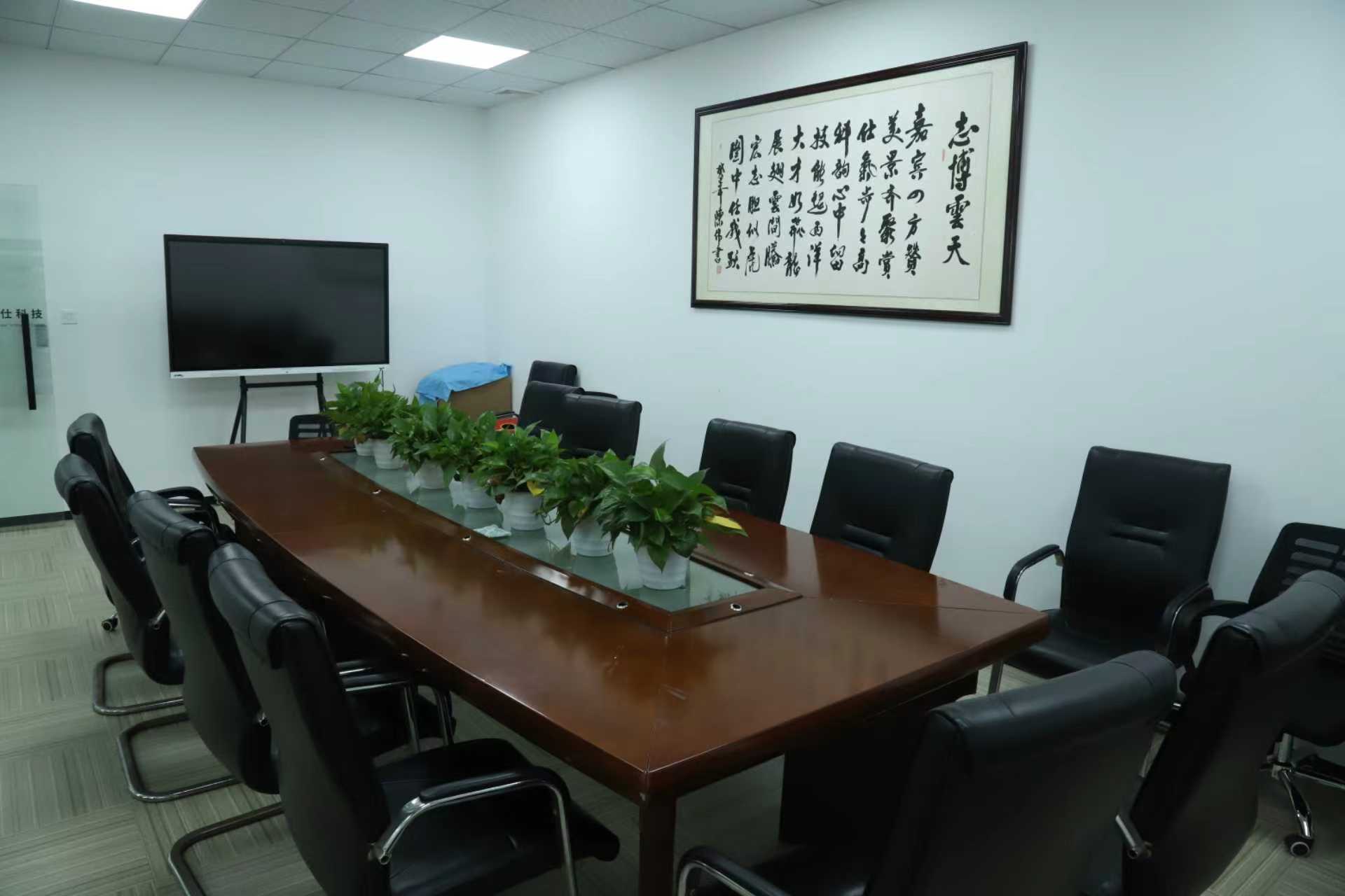
Shenzhen Jumpstar Technology Co., Ltd. (JUMPSTAR) is a GNSS hardware manufacturer based in Shenzhen, China, founded in 2013. The company operates a 5,000 m² facility with 200 employees and a 20-engineer R&D team, producing RTK modules, GNSS boards, smart antennas, GNSS antennas and RTK receivers for export markets in the EU, USA and Middle East. Contact: Room 1305, Block A, Building 1, Lechuanghui Mansion, No. 1211 Guanguang Road, Longhua District, Shenzhen, China 518110.
Have Questions or Need More Details?
Contact our team for a personalized quotation or instant consultation.
Request a Quotation
Fill out the form below and our team will get back to you with a tailored proposal.
WhatsApp Direct Chat
Prefer to chat in real-time? Message us on WhatsApp for instant assistance & quick answers.
- Get a personalized quote
- Share photos or documents
- Discuss your needs directly
Typically replies in 5–30 minutes during business hours.