
RTK Board vs GPS GNSS Module: Sub-Meter to Centimeter Accuracy
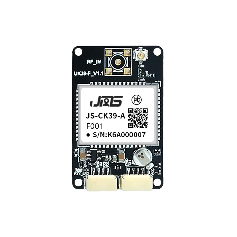
In one line: an RTK board and a GPS GNSS module are not competing products — they sit at different layers of the same accuracy stack, and the choice between them is decided by the accuracy contract your product has to sign, not by the brand printed on the silkscreen.
A standard-precision GPS GNSS module such as the Jumpstar JS-AP26-H delivers a finished position at 2.5 m CEP, tightening to 2.0 m with SBAS and 1.0 m with D-GNSS. A carrier-phase RTK board such as the JS-CK39-A exposes pseudorange measurements at ≤10 cm precision and carrier-phase measurements at ≤1 mm precision, which is what makes RTK output of H±(8+1ppm×D) mm possible at all. Between those two endpoints sit dual-band GNSS modules that reach 1.0 m horizontal, and RTK GNSS modules that place a complete RTK engine inside a 16.2 × 12.2 × 2.3 mm footprint.
This technical breakdown covers what changes inside the receiver, how correction processing and carrier-phase tracking differ, how update rates and protocols map onto real integration work, and which parameter trade-offs an engineer should weigh before locking a design.
The Real Question Behind “RTK Board vs GNSS Module”
The phrase “GPS GNSS module” describes a form factor and an output contract: a self-contained receiver that publishes a computed position, usually as NMEA 0183 sentences that a host can read directly. The phrase “RTK board” describes a board-level assembly that carries the RTK engine, the raw measurement interface, and usually additional sensing such as an IMU.
Both descriptions can be true of hardware in the same size class, which is why the comparison needs to be rebuilt around three engineering questions:
- What accuracy does the application actually require? Meter-level, sub-meter and centimeter-level are three different hardware classes, not three tuning options on one product.
- Where does correction and carrier-phase processing run? In the host processor, inside the module, or on the board — this determines both the bill of materials and the firmware work.
- Which physical, electrical and protocol constraints close the decision? Supply voltage, current budget, interface count, antenna bias, update rate and temperature range usually eliminate options faster than accuracy does.
In practice, sub-meter projects are frequently over-specified with an RTK board, and centimeter projects are frequently under-specified with a meter-level module. Both mistakes are avoidable once the measurement layer is separated from the positioning layer.
Industry Background: Why the Accuracy Class Decision Is Getting Harder
The commercial context explains why more integrators are now asked to justify an accuracy class. The global high-precision GNSS market was valued at USD 7.8 billion in 2024 and is projected to reach USD 20.6 billion by 2033 (Dataintelo). Within that, the high-precision GNSS module segment alone was estimated at USD 1.5 billion in 2024 and is forecast to reach USD 4.5 billion by 2035 (Market Research Future). EUSPA forecasts GNSS downstream market revenues of €580 billion by 2034.
Agriculture is the dominant application area, holding a 36.8% share of high-precision GNSS applications in 2025, with the precision farming market projected to grow from USD 11.38 billion in 2025 to USD 21.45 billion by 2032 (MarketsandMarkets). Standardisation is following the same curve: ISO 12188 parts 1 and 2 define test procedures for positioning and guidance systems in agriculture and forestry, and the Galileo High Accuracy Service delivers horizontal accuracy down to 20 cm.
Two consequences follow for engineers specifying hardware:
- Sub-meter is becoming a service-level expectation rather than a premium feature. Widely available correction signals continue to compress the gap between ordinary code-based positioning and full carrier-phase RTK.
- Centimeter work still requires the measurement layer. Reaching centimeter accuracy requires carrier-phase observables and RTK processing; no firmware improvement on a code-only module substitutes for that.
That is the fork in the road: one branch optimises integration effort and size, the other optimises measurement fidelity.
How an RTK Board Processes Corrections and Carrier Phase
A carrier-phase RTK board is defined less by its connector layout than by what it publishes to the host. Jumpstar’s JS-CK39-A, a multi-band multi-constellation GNSS receiver with a built-in IMU, is a representative example of the architecture.
Signal tracking and raw measurement output
The board tracks GPS L1C/A, L2P and L2C; BDS-2 B1I and B2I; BDS-3 B1C and B2b; GLONASS G1 and G2; Galileo E1 and E5b; QZSS L1C/A and L2C; and SBAS L1C/A. Tracking sensitivity is -155 dBm with re-acquisition at -138 dBm. Time to first fix is under 20 seconds cold and under 10 seconds hot, and lost-lock re-acquisition is under 1 second.
The measurement figures are the part that matters most for accuracy planning:
- Pseudorange precision: ≤10 cm
- Carrier-phase precision: ≤1 mm
- Speed precision: ≤0.02 m/s
- Time precision: 20 ns
Carrier-phase tracking produces an observable roughly two orders of magnitude finer than code tracking. That precision is what allows an RTK engine to resolve integer ambiguities and turn a metre-class code solution into a centimetre-class phase solution. Single-point performance of the JS-CK39-A is H≤1.5 m and V≤3 m (1σ, PDOP≤4); in RTK mode it is H±(8+1ppm×D) mm and V±(15+1ppm×D) mm.
Correction intake and protocol support
A board at this level has to accept corrections in whatever format the correction service or base station provides. The JS-CK39-A supports NMEA 0183, a custom binary protocol, CMR, and RTCM 2.X as well as RTCM 3.X including MSM3 through MSM7 message types. MSM messages carry multi-constellation, multi-signal observations, which is what makes multi-band RTK baselines practical.
Data rate, IMU and timing
Data rate on the board is selectable: measurements and position can run at 100 Hz as an option, with RTK positioning at 20 Hz as an option. The integrated IMU is specified with a gyro range of ±250°/s and 0.5°/s zero bias, and an accelerometer range of 4 g with 20 mg zero bias — useful when the host needs attitude output or continuity through short GNSS dropouts.
Electrically and physically, the board runs from 3.3 to 5.5 V DC and consumes 0.8 W at 3.3 V, rising to 0.9 W with anti-interference enabled. It measures 25.0 × 39.4 × 11.6 mm ±0.3 mm, provides 2×UART, RF_IN, PPS, VCC and GND, and is rated from -40 °C to +85 °C with 95% non-condensing humidity. The antenna interface expects 50 Ω, supplies LNA bias power of +3.3 V to +5 V, and suggests an LNA gain of 20–35 dB.

What a GPS GNSS Module Optimises Instead
A standard-precision GNSS module solves a different problem: it removes the positioning work from the host entirely. The JS-AP26-H is a single-frequency multi-mode module measuring 16.0 × 12.2 × 2.4 mm ±0.3 mm. It tracks GPS/QZSS L1C/A, BDS B1I and B1C, GLONASS L1, Galileo E1 and SBAS, with tracking sensitivity of -162 dBm and a cold start of 28 seconds.
Its published accuracy figures define the practical ceiling of the class: 2.5 m for standalone GNSS, 2.0 m with SBAS, and 1.0 m with D-GNSS correction. Time accuracy is 25 ns on 1PPS and the maximum update rate is 10 Hz. Interfaces include UART, I2C, USB 2.0 FS, PPS and RF_IN, with a supply range of 1.8 to 3.6 V and typical acquisition current of 38–45 mA at 3.3 V.
Dual-band modules move the sub-meter line
The more interesting shift sits one tier up. Dual-band modules receive L1 and L5 concurrently, and that changes the achievable accuracy without adding an RTK engine:
- JS-ATP45-M — 45.0 × 45.0 × 13.0 mm, 135 channels (L1: 75, L5: 60), horizontal accuracy 1.0 m on L1+L5 and 2.5 m on L1 alone, vertical 2.25 m, 1PPS at 10 ns, 10 Hz maximum update rate.
- JS-ATP36-M — 36.0 × 36.2 × 12.5 mm, same accuracy class, available with TTL (UART + I2C) or RS232 interfaces.
- JS-ATP30-M — 30.0 × 30.0 × 12.5 mm, available with UART, USB or RS232 interface versions.
- JS-AP08-PR — the miniaturisation end of the range: 8.0 × 6.0 × 2.3 mm ±0.1 mm, under 1 g, 21 mA at 3.3 V, 2.5 m accuracy, and a maximum update rate of 1 Hz by default, configurable up to 5 Hz.
- JS-AD56UB8 — a UAV-oriented module built on a high-performance GNSS chip with over 2 million effective correlators, 72 search and 24 capture channels, -167 dBm tracking sensitivity, 2.5 m autonomous accuracy and 2.0 m with SBAS, offered in TTL, CAN, TTL+MCU and TTL+barometer versions.
For applications that need a robust fix, fast re-acquisition and low power, this class is usually the correct answer — and it costs measurably fewer engineering hours than an RTK design.

RTK GNSS modules: the middle layer
Between the two extremes sits the category that confuses procurement most often: modules that contain a full RTK engine inside a module footprint.
- JS-RK26-3 — 16.2 × 12.2 × 2.3 mm ±0.3 mm, 200 tracking channels, dual-band L1/L5 across GPS, BDS, Galileo, GLONASS, QZSS, IRNSS and SBAS, RTK accuracy of 1.0 cm+1ppm horizontal and 1.5 cm+1ppm vertical, typical current of 20 mA at 3.3 V, PPS timing of 20 ns RMS, and a 20 Hz maximum update rate.
- JS-ARK28-3 — 28.0 × 28.0 × 8.0 mm, RTK 1.0 cm+1ppm horizontal, 37 mA typical at 3.3 V, 20 Hz maximum update rate.
- JS-ARK37-3 — 36.0 × 36.0 × 9.7 mm, RTK 1.0 cm+1ppm horizontal, 42–53 mA at 5 V, TTL by default with optional RS232 or CAN.
- JS-UK40 — RTK accuracy of 2 cm+1ppm horizontal on baselines up to 30 km, with a maximum update rate of 20 Hz for GPS RTK and 7 Hz for full-GNSS RTK.
The distinction that matters is not size but exposure. These modules deliver a centimetre-class position; they do not hand the host the raw carrier-phase stream that a board does. If the product needs centimetre accuracy and nothing more, a module is the shorter path. If the product needs to own the estimation layer — for sensor fusion, logging, custom correction handling or internal traceability — the board is the right level.
Seven Steps to Specify the Right Architecture
- Fix the accuracy contract first. Write down the required horizontal accuracy under the worst realistic sky view: 2.5 m (standalone module), 1.0 m (dual-band module or D-GNSS), 1–2 cm (RTK module), or ±8 mm + 1 ppm × baseline distance (RTK board). Everything downstream follows from that single number.
- Decide where the RTK engine lives. Board-level: the host consumes raw measurements and runs its own estimation. Module-level: the module outputs an RTK position and the host only has to supply a correction input.
- Confirm correction transport and protocol. The JS-CK39-A board supports RTCM 2.X, RTCM 3.X with MSM3–MSM7, CMR, NMEA 0183 and a custom binary protocol. RTK modules in the same portfolio support NMEA 0183 and RTCM 3.X. If your correction network or base station uses a proprietary format, verify it against the module protocol list before designing.
- Match the antenna and RF front end. The JS-CK39-A expects a 50 Ω antenna input with +3.3 V to +5 V bias and suggests 20–35 dB LNA gain. The JS-RK26-3 accepts an active antenna with 15–30 dB gain and a maximum noise figure of 1.5 dB, and is also compatible with a passive antenna. Antenna choice then sets phase-centre stability: the JS-HAC100B survey antenna specifies a phase-centre error of ±2 mm with 40±2 dB LNA gain and IP67 protection, while the JS-HAC18A-F helical UAV antenna weighs 10.8 g with 33±2 dB LNA gain, ≤3 dB axial ratio and IP65 protection.
- Check the timing and update-rate budget. Time precision is 20 ns on the JS-CK39-A, 20 ns RMS on the JS-RK26-3, 25 ns on the JS-AP26-H and 10 ns on the dual-band JS-ATP45-M. Maximum update rates run from 10 Hz on most standard modules up to a 100 Hz optional measurement and positioning rate on the board. High-dynamic control loops usually need the higher end.
- Verify power, size and thermal envelope. The board draws 0.8–0.9 W at 3.3 V, while a module of the JS-AP26-H class draws 38–45 mA at 3.3 V. Several dual-band and RTK modules note a Farad capacitor operating window of -25 °C to 60 °C, outside which hot start is unavailable — a detail worth checking against your cold-start specification.
- Validate on a bench before committing to tooling. Order a single unit, verify carrier-phase stability or position repeatability with your own antenna and correction source, then scale. Production parameters for OEM/ODM work are a 500-unit minimum order quantity, a typical 30-day lead time and monthly capacity of 50,000 units, with 100% testing before shipment.
Trade-offs and Design Limits
Neither architecture is free of constraints, and stating them early avoids late redesigns.
- An RTK board does not produce accuracy on its own. It needs a correction source, a suitable antenna, and host firmware that consumes raw measurements. Without a baseline setup or network corrections, single-point accuracy stays at the H≤1.5 m / V≤3 m level.
- Module accuracy figures are conditional. The 1.0 m and 2.5 m numbers published for the module families assume open sky, and the D-GNSS and SBAS improvements require the corresponding correction signal to be present.
- Dual-band is not RTK. The 1.0 m horizontal figure on the JS-ATP45-M, JS-ATP36-M and JS-ATP30-M comes from concurrent L1+L5 reception, not from carrier-phase ambiguity resolution. Treat these as sub-meter class devices, not centimetre class.
- Environmental ratings differ by product, not by category. The JS-CK39-A is specified from -40 °C to +85 °C; the JS-UK43 smart antenna is specified across the same operating range with a 95% humidity limit; the JS-X11 base-station receiver is IP66 rated from -20 °C to +75 °C. Match the individual specification to the installation, not the product family.
Application Mapping: Which Class Fits Which Job
The same portfolio is used very differently across verticals, which is a useful sanity check when your own requirement is still unclear.
- UAV and drone platforms: a standard module handles flight-control positioning — the JS-AD56UB8 offers 2.5 m autonomous accuracy with -167 dBm tracking sensitivity — while mapping and survey payloads move to RTK, such as the JS-A56U9D with 192 search and 60 tracking channels, 0.05 m/s velocity accuracy, 0.3° dynamic heading accuracy and an 80,000 m altitude limit. Light airframes typically pair these with the JS-HAC18A-F helical antenna.
- Precision agriculture: dual-band modules such as the JS-ATP45-M and JS-ATP36-M provide the 1.0 m class used in auto-steering and implement guidance, with ISO 12188-1 and -2 available as the test-procedure reference for positioning and guidance systems in agriculture and forestry.
- Autonomous vehicles and robotics: the JS-CK39-A board suits designs that need raw measurements plus IMU, while the S-C8A RTK module with IMU specifies carrier-phase measurement precision of ≤1 mm, an optional 100 Hz measurement and positioning rate, centimetre-level accuracy for 3 seconds of GNSS loss, and metre-level accuracy for 10 seconds.
- Surveying and mapping: phase-centre stability dominates here, which is why the JS-HAC100B (±2 mm phase-centre error, IP67) and the JS-YAC130N integrated communication and navigation survey antenna (Ø130 × 15 mm) are specified for geodetic, marine and construction survey work.
- Marine and fleet operations: the JS-HAC148A quad-system full-frequency RTK antenna covers 1164–1278 MHz and 1559–1606 MHz with an IPX6 rating, while the JS-HAS37 L1/L5 antenna draws 8±3 mA at 3.3 V for low-power vehicle terminals.
- Heading-dependent systems: dual-antenna products such as the JS-SK43H-AH and the JS-NK43-2 (1408 channels with an integrated high-gain helical antenna) output heading and attitude without relying on magnetic sensing.
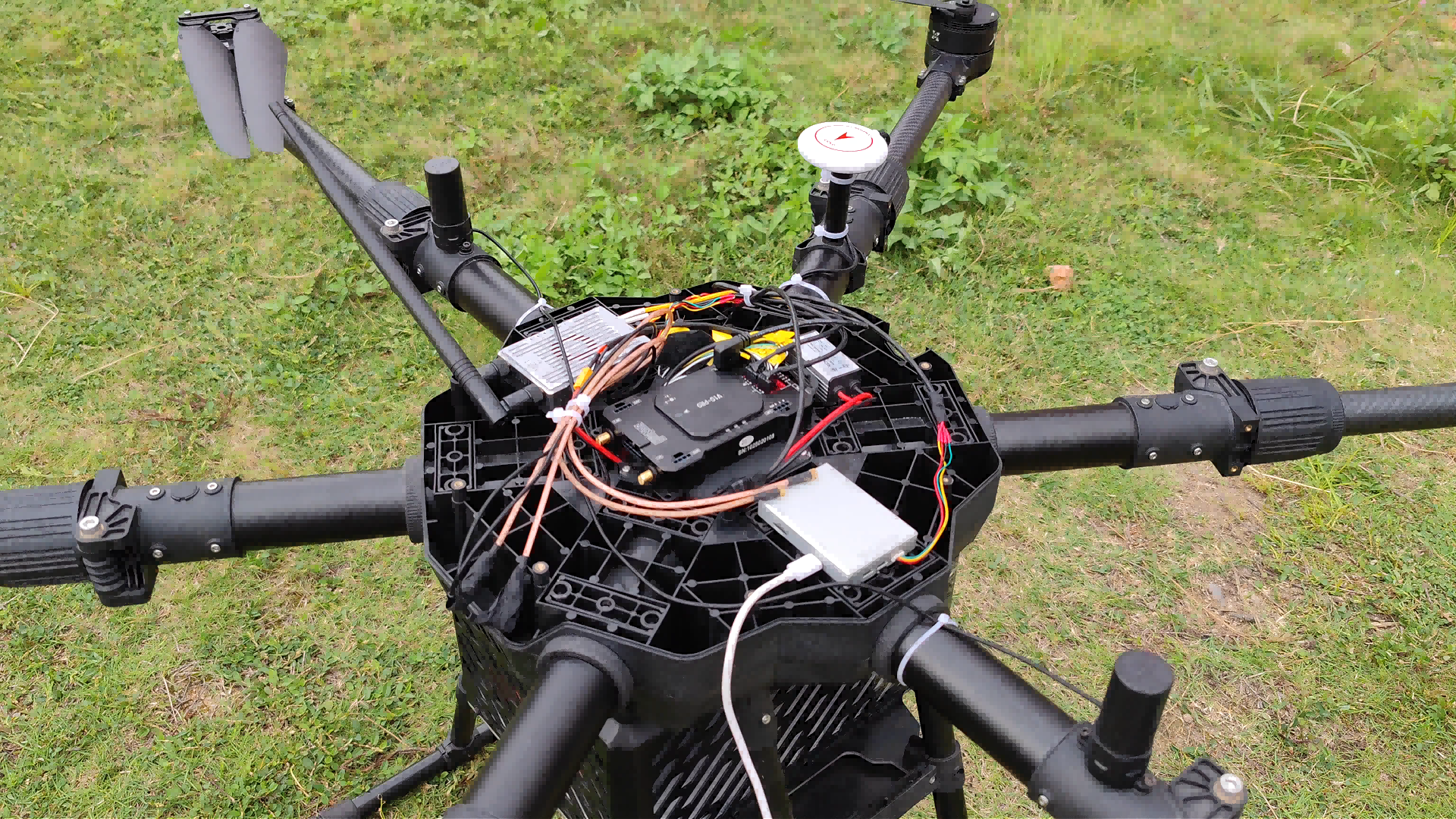
A concrete example of the heading point above: a drone manufacturer programme running for five years, built on 544 hardware channels with triple-band multi-constellation support and industrial-grade AIM+ anti-jamming and anti-spoofing technology, achieved centimetre-level RTK positioning and heading accuracy of 0.03° at a 5 m baseline without relying on magnetic sensors for attitude output. The units are deployed by clients in India, China, the UAE and the Czech Republic.
Side-by-Side Parameter Comparison
The table below compares one carrier-phase RTK board, one RTK module with INS, one dual-band module and one single-frequency module from the same portfolio, using published parameters only.
| Parameter | RTK board — JS-CK39-A | RTK module with INS — JS-RK26-U | Dual-band module — JS-ATP45-M | Single-frequency module — JS-AP26-H |
|---|---|---|---|---|
| Category | High Precision GNSS OEM Board | RTK GNSS Module with IMU | Standard Precision GNSS Module | Standard Precision GNSS Module |
| Dimensions | 25.0 × 39.4 × 11.6 mm ±0.3 mm | 16.2 × 12.2 × 2.3 mm ±0.3 mm, <1.1 g | 45.0 × 45.0 × 13.0 mm ±0.3 mm | 16.0 × 12.2 × 2.4 mm ±0.3 mm |
| Constellations / bands | GPS L1C/A, L2P, L2C; BDS-2 B1I, B2I; BDS-3 B1C, B2b; GLONASS G1, G2; Galileo E1, E5b; QZSS L1C/A, L2C; SBAS L1C/A | GPS L1/L5; BDS B1I/B1C/B2I/B2B/B2A; GLONASS G1; Galileo E1/E5; QZSS L1/L5; IRNSS L5; SBAS | GPS L1CA/L5; BDS B1I/B2a; GLONASS L1OF; Galileo E1B/E1C/E5a; QZSS L1CA/L1SAIF/L5; SBAS | GPS/QZSS L1C/A; BDS B1I/B1C; GLONASS L1; Galileo E1; SBAS |
| RTK accuracy | H ±(8+1ppm×D) mm; V ±(15+1ppm×D) mm | H 1.0 cm + 1 ppm; V 1.5 cm + 1 ppm | Not specified in the published parameter set | Not specified in the published parameter set |
| Standalone accuracy | H ≤1.5 m, V ≤3 m (1σ, PDOP≤4) | H 1.0 m, V 2.0 m (single point) | H 1.0 m (L1+L5) / 2.5 m (L1); V 2.25 m | 2.5 m GNSS; 2.0 m SBAS; 1.0 m D-GNSS |
| Raw measurement precision | Pseudorange ≤10 cm; carrier phase ≤1 mm; time 20 ns | Not specified in the published parameter set | Not specified in the published parameter set | Not specified in the published parameter set |
| Max data rate | Measurement/position 100 Hz (optional); RTK 20 Hz (optional) | 10 Hz (default 1 Hz) | 10 Hz (default 1 Hz) | 10 Hz (default 1 Hz) |
| Correction protocols | NMEA 0183, custom binary, CMR, RTCM 2.X, RTCM 3.X (MSM3–MSM7) | NMEA 0183, RTCM3.X, private binary protocol | NMEA 0183 V3.01/V4.10 | NMEA 0183 V4.00/V4.10 |
| Main interfaces | 2×UART, RF_IN, PPS, VCC, GND | UART (TX/RX), 1PPS, RF_IN, VCC_RF, RESET_N, I2C (internal IMU) | SCL, RXD/DP, TXD/DM, GND, VCC, SDA | UART, I2C, USB 2.0 FS, PPS, RF_IN |
| Supply / current | 3.3–5.5 V DC; 0.8 W (0.9 W with anti-interference) @3.3 V | VCC 2.0–3.6 V; average 18–32 mA @3.3 V; standby 14 µA | VCC 2.8–5.5 V; acquisition 36–42 mA @5 V | VCC 1.8–3.6 V; acquisition 38–45 mA @3.3 V |
| Built-in IMU | Yes — gyro range ±250°/s, zero bias 0.5°/s; accelerometer 4 g, zero bias 20 mg | Yes — six-axis MEMS; GNSS loss within 120 s keeps positioning error ≤5% | No | No |
| Typical fit | Centimetre-level hosts that need raw measurements, IMU data and high-rate output | Compact centimetre-level designs inside a module footprint with INS continuity | Sub-meter products needing dual-band robustness and low integration effort | Meter-level products needing a small, low-power positioning output |
Read the table by column, not by row: the RTK board is the only column that publishes raw measurement precision, and the two standard modules are the only columns that publish neither RTK accuracy nor measurement precision. That asymmetry is the decision.

Frequently Asked Questions
Published parameter sets for the module and board families state RoHS compliance. At the manufacturing level, Jumpstar holds an ISO 9001:2015 quality management system certificate, number UQ231801R2, issued by Beijing United Intelligence Certification Co., Ltd. The scope covers R&D and sales of GPS modules, and the certificate is valid from 2023-12-11 to 2026-12-10, applicable to the EU, USA, Middle East, Africa and Asia. Quality control includes 100% testing of all units. Note that an ISO 9001 certificate is a management-system credential rather than a product type-approval, so market-specific product requirements should be confirmed separately for the destination market.
Sub-meter is achievable without carrier-phase RTK in some configurations. The single-frequency JS-AP26-H lists 2.5 m for standalone GNSS, 2.0 m with SBAS and 1.0 m with D-GNSS. The dual-band JS-ATP45-M, JS-ATP36-M and JS-ATP30-M list 1.0 m horizontal on L1+L5 and 2.25 m vertical. To go below that, a carrier-phase RTK engine is required: the JS-RK26-3 and JS-RK26-U deliver RTK accuracy of 1.0 cm+1ppm horizontal and 1.5 cm+1ppm vertical, while the JS-CK39-A board delivers H±(8+1ppm×D) mm plus raw carrier-phase measurements at ≤1 mm precision.
Jumpstar (JUMPSTAR CO., LIMITED / Shenzhen Jumpstar Technology Co., Ltd.) is a Shenzhen-based GNSS positioning hardware manufacturer founded in 2013, operating a 5,000 m² facility with 200 employees, 20 R&D engineers and an annual output of 100,000 units, with 70% of production exported to the EU, USA and Middle East. OEM and ODM services cover modules, PCBA, antennas, functions, ports, interfaces and logo, with a monthly production capacity of 50,000 units. For UAV work specifically, the portfolio includes the JS-AD56UB8 standard-precision module for UAV flight control, the JS-A56U9D RTK module for UAVs and GIS, the JS-HAC18A-F helical UAV antenna, and RTK hardware already deployed in drone-manufacturer programmes.
For OEM/ODM production the minimum order quantity is 500 units, the typical lead time is 30 days, and monthly production capacity reaches 50,000 units, with 100% testing during quality control and remote after-sales support. The procurement support record separately lists a minimum order of 1 unit with EXW delivery, 100% test before shipping, and flexible payment terms by T/T. The two figures serve different purposes: the 500-unit MOQ applies to customised OEM/ODM runs, while the 1-unit minimum supports standard-product purchasing.
Because single-unit purchasing is supported at EXW with 100% testing before shipment, a team can buy one unit, connect it to its own antenna and correction source, and measure position repeatability or carrier-phase stability on the bench before tooling. Engineering support is provided remotely, and customised modules, PCBA, antennas, functions, ports and interfaces are available once the design is fixed. To start sample validation, request a quotation or sample from sales@jgnss.com or WhatsApp +86 136-2236-7049, and review the full capability overview in the Jumpstar company profile 2026.
Conclusion: Choose the Measurement Layer, Then the Form Factor
The accuracy target decides the architecture. Meter-level positioning is a module problem, and the JS-AP26-H class solves it at 2.5 m standalone with 2.0 m SBAS and 1.0 m D-GNSS. Sub-meter positioning is a dual-band problem, solved by the JS-ATP45-M, JS-ATP36-M and JS-ATP30-M at 1.0 m horizontal on L1+L5. Centimeter positioning is a carrier-phase problem: the JS-RK26-3 and JS-RK26-U place an RTK engine at 1.0 cm+1ppm inside a 16.2 × 12.2 × 2.3 mm module, while the JS-CK39-A board goes further and hands the host raw carrier-phase measurements at ≤1 mm precision, IMU data, optional 100 Hz measurement output and the full RTCM 2.X/3.X MSM3–MSM7 correction set.
Once the measurement layer is settled, the remaining decisions — size, power, interfaces, antenna bias, thermal envelope and protocol support — are ordinary engineering trade-offs rather than accuracy risks.

Next Step: Validate on Your Own Bench
Send your accuracy target, constellation and update-rate requirement, and host interface constraints. Jumpstar supports single-unit sample orders at EXW, 100% testing before shipment, OEM/ODM customisation of modules, PCBA, antennas, functions, ports and interfaces, and a 30-day typical lead time for production runs.
Email: sales@jgnss.com | WhatsApp: +86 136-2236-7049 | Website: www.jgnss.com
Download the Jumpstar company profile 2026 (PDF) for full product and capability details.