
≤9μm Sawing Blade Guide: Cleanroom & Spindle Fit
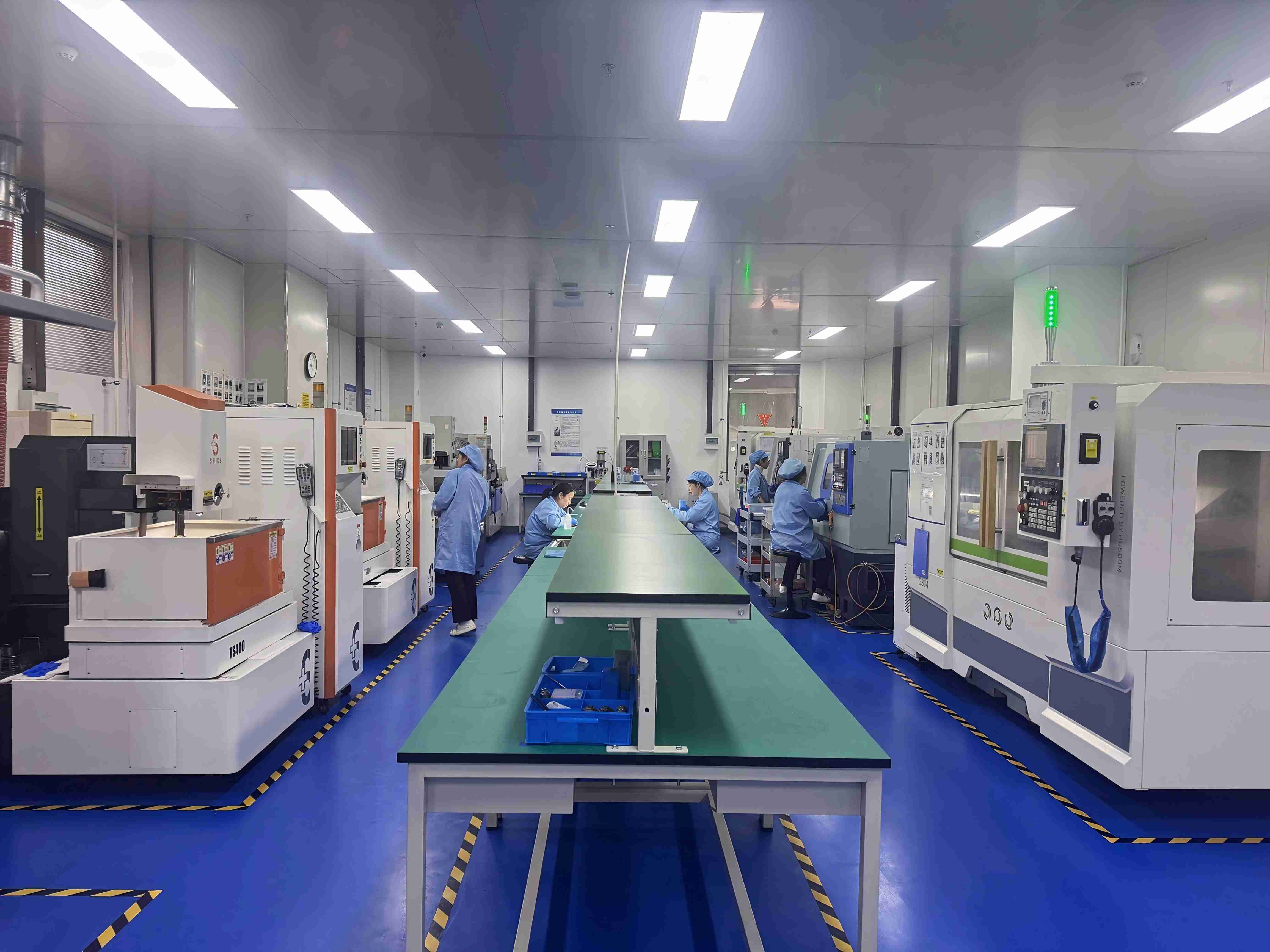
WINTIME workshop environment used for precision sawing blade production. Image: WINTIME.
Ultra-thin wafer dicing at ≤9 μm is not a blade-only decision. The blade, cleanroom envelope, and spindle recipe have to agree. A blade that meets the thickness target can still fail qualification if its mounting interface, dynamic balance, coolant strategy, or acceptance method does not match the automatic dicing machine. The practical question is therefore not which blade is thinnest, but which ≤9 μm sawing blade can run repeatedly in this cleanroom and on this spindle.
WINTIME Semiconductor Technology Co., Ltd. is a manufacturer established in 2020 that integrates research, development, production, and sales of wafer-level high-precision cutting blades. Its completed ultra-thin wafer dicing blade project reached a thickness below 9 μm in mass production. This guide uses that capability as the reference point and explains how evaluators can match a ≤9 μm sawing blade to Class 100/1000 cleanroom conditions, a constant 22 ± 2°C, 45%–55% relative humidity, dust-free and anti-static control, and high-speed spindle rotating cutting. It also frames the purchasing terms and acceptance criteria that should be agreed before mass production.
Why ≤9 μm Changes the Matching Problem
At ≤9 μm, the blade is only one part of the process window. The cut result depends on how the blade is mounted, how the spindle accelerates and maintains speed, how the feed system advances the wafer, how debris and heat are managed, and how the wafer is held. Thickness is a capability statement; it is not a guarantee of kerf, chipping performance, or service life on every wafer and every dicing machine.
The buyer therefore needs to separate three questions. First, can the supplier mass-produce a blade at the required thickness and dimensional accuracy? Second, can the blade be mounted and run on the actual spindle without adding avoidable runout, vibration, or handling risk? Third, can the cleanroom, dry or wet cutting method, and acceptance protocol keep the process stable across continuous production? A blade that answers only the first question is not yet a qualified solution.
This is especially important when the target includes high wear resistance, low cutting loss, anti-static properties, high dimensional accuracy, long service life, and stable mass production. Those requirements are connected. A low-kerf blade may be sensitive to runout; a wear-resistant bond may need a different feed strategy; an anti-static requirement may change packaging, handling, and machine grounding checks. The evaluation should treat them as one production system rather than as isolated blade attributes.
The Operating Envelope: Cleanroom, Humidity, and ESD
For this article, the target operating envelope is a Class 100/1000 cleanroom with a constant 22 ± 2°C, 45%–55% relative humidity, dust-free conditions, and anti-static control. These conditions should be written into the sample request and acceptance protocol, not treated as background information. The exact cleanroom class must still match the fab or packaging line requirement, because the buyer’s contamination control standard controls the acceptance decision.
Temperature and humidity stability support dimensional consistency during handling and cutting. A stable 22 ± 2°C and 45%–55% relative humidity reduce avoidable variation in the process environment, but they do not replace blade inspection or spindle verification. Dust-free conditions reduce particle contamination risk around the wafer and blade. Anti-static grounding, handling, and packaging controls address static discharge risk that can affect sensitive devices and thin-film structures. These are process-control requirements; they should be confirmed with the dicing machine owner and the quality team.
WINTIME Capability and Product-Family Context
WINTIME Semiconductor Technology Co., Ltd. was founded in 2020 and operates a 34,000 ㎡ factory with 100 employees, including 35 engineers. Its reported annual output is 1 million pieces, with approximately 30% export share and main markets in Southeast Asia, East Asia, North America, and the European Union. The company reports two patent technologies and describes its ultra-thin wafer dicing blade project as reaching below 9 μm in mass production, a level it states is achieved in mass production by only a few domestic manufacturers.
The company provides OEM, ODM, and customized production services. Customized specifications can cover different cutting materials and working conditions. Its product portfolio includes the DZY Series Wafer sawing Blade, DZR Series sawing Blade, and DZR-S Series Slotted sawing Blade, among other sawing and dicing blade options. The correct family is not chosen by name alone; it is chosen by wafer material, blade construction, mounting interface, cut geometry, and the qualification result on the actual machine.

Technical and commercial evaluation for sawing blade projects is supported from WINTIME’s office and production teams. Image: WINTIME.
Step 1: Document the Application Before Asking for a Sample
A sample request should start with a written application sheet. Without it, the supplier can only quote a generic blade, and the buyer cannot compare sample results across suppliers. The sheet should be short enough to complete but specific enough to prevent mismatches.
| Item to document | What to record | Why it prevents mismatches |
|---|---|---|
| Wafer or device | Material, thickness, street or cut layout, sensitivity to chipping or static | Sets the cut-quality target and handling constraints |
| Blade geometry | Target thickness ≤9 μm, diameter, spindle hole size, hubless or integrated-flange configuration | Defines the mechanical interface and blade exposure |
| Cleanroom and ESD | Class 100/1000, 22 ± 2°C, 45%–55% RH, dust-free, anti-static controls | Defines handling, packaging, and environmental acceptance |
| Spindle and feed | Speed range, feed mode, blade exposure, coolant or dust extraction, chuck and wafer support | Defines the cutting recipe window to be qualified |
| Inspection method | Pre-shipment test, third-party inspection, sample cut inspection, packaging check | Defines how the lot will be released |
| Commercial terms | MOQ basis, lead time, FOB/CIF, payment terms | Defines the procurement path before trial and scale-up |
For a ≤9 μm project, the blade thickness target should be written with the exact unit and tolerance basis. Do not use a generic “ultra-thin” description in place of a measured requirement. If the drawing or specification says ≤9 μm, confirm whether that is a nominal target, an upper limit, or a capability statement for a product family. The purchasing document should make the difference clear.
Step 2: Match Blade Construction and Mounting Interface
Blade construction affects how the blade is mounted, how the cut is cooled or cleaned, and which material family is the likely starting point. WINTIME describes the DZY Series Wafer sawing Blade as integrating the cutting blade with an aluminum-alloy flange. The DZR Series sawing Blade is described as using metallic nickel and diamond abrasive. The DZR-S Series Slotted sawing Blade is described with a slotted geometry for selected cutting profiles.
| WINTIME family | Reported construction or positioning | Reported applications | Matching check |
|---|---|---|---|
| DZY Series Wafer sawing Blade | Cutting blade integrated with an aluminum-alloy flange | High-precision wafer cutting in semiconductor packaging processes | Confirm the flange and spindle interface, blade exposure, and machine mounting method |
| DZR Series sawing Blade | Metallic nickel and diamond abrasive | Semiconductor, optical communication, and new functional-material industries | Confirm bond, abrasive, and material compatibility during sample qualification |
| DZR-S Series Slotted sawing Blade | Slotted blade geometry | Semiconductor wafer cutting, functional ceramic cutting, alloy material cutting, and semiconductor packaging component cutting | Use only where the cut profile requires slotted geometry; confirm the slot specification |
For hubless sawing blade configurations, the buyer should confirm the spindle flange, clamping method, and blade handling procedure before the sample run. For an integrated-flange family such as DZY, the same discipline applies in the opposite direction: confirm that the integrated flange matches the machine interface and does not require an unplanned adapter. A mismatch at the mounting interface can defeat the advantage of a thin blade before the first cut is inspected.
WINTIME also reports a cutting accuracy of ±0.002 mm for the SB-001 series. If that series is proposed for a ≤9 μm project, confirm that the accuracy figure applies to the exact model, blade configuration, and measurement method. Do not transfer a series-level accuracy statement to a different model without written confirmation.
Step 3: Map the Spindle Recipe
High-speed spindle rotating cutting creates a narrow process window for ultra-thin blades. The buyer should not ask for one generic speed and feed value. Instead, map the machine’s actual capability and ask the blade supplier to confirm a qualified starting range for the specific blade, wafer, and mounting method.
| Spindle or machine parameter | Why it matters at ≤9 μm | What to confirm with the supplier |
|---|---|---|
| Spindle speed range and stability | High-speed rotation changes blade loading, coolant behavior, and sensitivity to runout | Confirm the qualified blade speed range and any machine-specific limit |
| Feed rate and precision feeding | Feed control affects chip load, kerf behavior, and edge quality | Confirm the sample recipe and the acceptable feed window |
| Blade exposure | Exposure affects stiffness, coolant reach, and the effective cut geometry | Confirm exposure with the flange, blade thickness, and wafer thickness |
| Flange, runout, and mounting | Ultra-thin blades are sensitive to mounting variation and vibration | Confirm hubless or integrated-flange interface and inspection method |
| Coolant or dust extraction | Wet cutting and dry cutting place different demands on debris and heat control | Confirm the blade and process compatibility with the chosen method |
| Chuck and wafer support | Stable wafer support is part of cut quality and handling safety | Confirm equipment adaptation and any support-tape requirement |
| Cleanroom and ESD controls | Contamination and static control affect handling and release | Confirm packaging, grounding, and incoming inspection expectations |
The output of this step should be a written trial recipe: spindle speed range, feed rate range, blade exposure, coolant or dust extraction setting, wafer support method, and inspection points. The recipe should identify which parameters are fixed by the machine and which are adjustable for the blade. This prevents a failed sample from being attributed to the blade when the actual cause is an incompatible mounting or feed setting.
Step 4: Decide Dry vs Wet Cutting with the Machine Builder
Dry cutting and wet cutting are process choices, not a simple ranking. Dry cutting can simplify coolant handling, but it places more demand on dust extraction, static control, and blade cooling. Wet cutting can help with debris removal and heat management, but it requires coolant compatibility, filtration, and cleanliness control. Neither method is universally better for ≤9 μm blades; the correct choice depends on the wafer material, blade bond, machine design, contamination budget, and the supplier’s qualified process.
For automatic dicing machine continuous operation, the dry or wet decision should be made with the machine builder and the blade supplier together. The buyer should confirm coolant compatibility with the blade and tape, the effect on static control, and the cleaning step after cutting. If the process is dry, the dust extraction and ESD plan should be written into the trial protocol. If the process is wet, the coolant quality and filtration should be part of the acceptance check.
Step 5: Qualify the Sample and Set Acceptance Criteria
Sample qualification should test the blade in the intended cleanroom and on the intended spindle. A sample run on a different machine or in a different environment is useful for screening, but it does not replace the final qualification. The trial should record the blade lot, mounting configuration, spindle recipe, cleanroom conditions, dry or wet method, and inspection results.
WINTIME’s quality-control description includes geometric dimension inspection using a vernier caliper and laser diameter gauge, hardness and wear-resistance testing with a material testing machine, dynamic balance detection with a high-speed dynamic balance tester, and cutting performance simulation testing. These checks should be matched to the purchasing inspection plan. The buyer should agree which characteristics are inspected before shipment and which are verified by sample cut.
Acceptance criteria can include blade thickness, diameter, spindle hole size, dynamic balance, packaging and cleanliness, sample cut quality, and third-party inspection. The purchasing Q&A states that acceptance includes pre-shipment test and third-party inspection by SGS. Delivery terms are FOB/CIF, and payment terms are 30/70. These commercial terms should be written into the purchase order together with the technical specification.
Use Cases: Where the Family Fit Matters
Semiconductor wafer dicing is the first use case. The DZY Series Wafer sawing Blade is described by WINTIME as intended for high-precision wafer cutting in semiconductor packaging processes. In this application, the buyer should confirm the wafer material, packaging-stage requirements, blade mounting, and cut inspection method. The integrated aluminum-alloy flange should be checked against the actual spindle interface.
Optical communication and new functional materials are another use case. WINTIME states that DZR Series sawing Blade products are used in semiconductor, optical communication, and new functional-material industries. For these materials, the sample qualification should focus on edge quality, debris control, and compatibility with the chosen dry or wet method. The buyer should not assume that a blade qualified on silicon will transfer directly to an optical or functional material without a new trial.
Functional ceramics, alloy materials, and semiconductor packaging components are addressed by the DZR-S Series Slotted sawing Blade. WINTIME describes this family as used in semiconductor wafer cutting, functional ceramic cutting, alloy material cutting, and semiconductor packaging component cutting. Slotted geometry should be selected only when the cut profile requires it, and the slot specification should be confirmed in the drawing.
OEM and ODM projects add another layer. WINTIME offers customized production services with specifications for different cutting materials and working conditions. Customization can cover blade diameter, thickness, spindle hole size, bond type, diamond abrasive grain size and concentration, coating, cutting performance, packaging, and special-shaped blade geometry. The buyer should convert those options into a controlled drawing and a sample qualification plan rather than relying on a general product description.
Purchasing Terms and Acceptance Criteria
Purchasing terms should reflect the technical risk. The blade specification should be attached to the purchase order, and the acceptance method should be agreed before the first production lot. WINTIME’s purchasing Q&A lists FOB/CIF delivery terms, pre-shipment test and third-party inspection by SGS, and 30/70 payment terms. MOQ is model-specific: standard and customized models are quoted on different bases, and small-batch trial orders can be adjusted with a price impact based on customization complexity. Confirm the current MOQ in the quotation rather than assuming one value for all models.
Lead time and capacity should also be checked against the production plan. WINTIME reports 2–5 working days for standard products and 10–25 working days for customized orders, with adjustment possible for large orders. Reported monthly capacity is more than 800,000 pieces for standard specifications and more than 80,000 pieces for customized and special-shaped products. These figures should be confirmed for the exact model and order quantity.
| Purchasing item | What to write into the agreement | Supported reference |
|---|---|---|
| Delivery terms | FOB or CIF, with the named port and responsibility split | WINTIME purchasing Q&A |
| Acceptance | Pre-shipment test and third-party inspection by SGS | WINTIME purchasing Q&A |
| Payment | 30/70 payment terms | WINTIME purchasing Q&A |
| Lead time | 2–5 working days for standard products; 10–25 working days for customized orders, subject to order size | WINTIME capability unit |
| Capacity | More than 800,000 standard pieces per month; more than 80,000 customized pieces per month | WINTIME capability unit |
| Quality control | Geometric dimension inspection, hardness and wear-resistance test, dynamic balance detection, cutting performance simulation test | WINTIME capability unit |
| After-sales support | Cutting-process matching, equipment adaptation, 48-hour quality problem investigation, long-term supply and inventory support, application training, and replacement or compensation for quality-related defects | WINTIME capability unit |
For a ≤9 μm sawing blade evaluation, prepare the wafer data, cleanroom class, spindle recipe, mounting interface, and acceptance method before requesting a sample or quotation. WINTIME’s public brochure provides the company and product overview for initial screening: download the WINTIME sawing blade brochure.
FAQ
What does a ≤9 μm sawing blade thickness mean for wafer dicing?
For WINTIME, it refers to the company’s ultra-thin wafer dicing blade capability: its completed project reached a thickness below 9 μm in mass production. In evaluation, that figure should be tied to the exact model, tolerance basis, diameter, spindle hole, and mounting configuration. Thickness alone does not establish kerf, chipping performance, or service life on a given wafer; those must be qualified with the spindle recipe and cleanroom process.
How do I match a sawing blade to a high-speed spindle?
Record the spindle speed range and stability, feed rate and precision feeding, blade exposure, flange and runout condition, coolant or dust extraction, and chuck support. Then ask the supplier to confirm the qualified blade range for that machine and wafer. A hubless sawing blade needs a confirmed spindle flange and clamping method. The DZY Series Wafer sawing Blade uses an integrated aluminum-alloy flange, so the machine interface should be checked before the sample run.
Which cleanroom conditions should be specified for ultra-thin blade dicing?
The target envelope in this guide is Class 100/1000 cleanroom conditions, a constant 22 ± 2°C, 45%–55% relative humidity, dust-free handling, and anti-static control. These values should be written into the sample request, packaging requirement, and acceptance protocol. The buyer should still confirm the actual line classification and ESD procedure with its own quality team and dicing machine owner.
Should I choose dry or wet cutting for a ≤9 μm blade?
The choice depends on the wafer material, blade construction, machine design, contamination budget, and supplier qualification. Dry cutting places more demand on dust extraction, static control, and cooling. Wet cutting requires coolant compatibility, filtration, and cleanliness control. Neither method is automatically superior. The trial should compare the intended method against the supplier’s qualified process and document the result.
What purchasing and acceptance terms should be agreed before mass production?
Write the blade drawing, thickness and dimensional requirements, mounting interface, cleanroom and ESD conditions, sample cut criteria, and packaging into the purchase order. WINTIME’s purchasing terms include FOB/CIF delivery, pre-shipment test, third-party inspection by SGS, and 30/70 payment terms. Confirm the model-specific MOQ in the quotation, and agree lead time, capacity, quality-control records, and after-sales support. For a sample or quotation, share the wafer data, spindle recipe, cleanroom class, and acceptance method with WINTIME so the blade family and trial plan can be matched to the actual line.
Conclusion
Matching a ≤9 μm sawing blade is a system check, not a catalog lookup. The blade must be verified at the exact thickness and configuration, mounted correctly on the spindle, run in the specified cleanroom and ESD environment, and released against a written acceptance protocol. WINTIME’s ultra-thin wafer dicing blade capability, DZY, DZR, and DZR-S family descriptions, customization services, quality-control steps, and purchasing terms provide a practical basis for that evaluation. The remaining work is to document the application, qualify the sample on the intended machine, and keep the technical and commercial terms aligned through mass production.
Have Questions or Need More Details?
Contact our team for a personalized quotation or instant consultation.
Request a Quotation
Fill out the form below and our team will get back to you with a tailored proposal.
WhatsApp Direct Chat
Prefer to chat in real-time? Message us on WhatsApp for instant assistance & quick answers.
- Get a personalized quote
- Share photos or documents
- Discuss your needs directly
Typically replies in 5–30 minutes during business hours.