
How Correct Blade Feed Prevents Large-Scale Die Defects in Wafer Dicing
A wrong blade feed does not damage one die. It damages the lot. On an automatic dicing machine, feed is the variable that turns a stable blade into a stable cut — or converts a small process drift into a wafer-scale defect event. Correct blade feed keeps chipping, kerf drift and edge cracking inside the specification window across every pass, every wafer and every production batch.
This guide is written for process engineers, dicing-line supervisors, quality teams and procurement managers who have already moved past blade discovery and are now executing: setting machine parameters, qualifying a sawing blade, and protecting yield over months of production. It explains how feed interacts with three blade properties that decide the outcome — narrow kerf geometry, anti-static and cleanroom-compatible behavior, and tight dimensional control — then gives a step-by-step method for locking a feed recipe and verifying it batch by batch.
WINTIME Semiconductor Technology Co., Ltd. is a Rugao City, Jiangsu Province manufacturer founded in 2020 that develops, produces and sells high-precision sawing blades (dicing blades), cutting tapes and full-process cutting solutions for semiconductor, optical, ceramic and alloy applications. Its blade families include the DZY Series wafer sawing blade, the DZR Series sawing blade and the DZR-S Series slotted sawing blade, alongside hubless and electroforming hard sawing blade types.

WINTIME planning and quality area, Rugao City, Jiangsu Province — where blade specifications and feed windows are matched to customer processes.
The Real Problem: One Feed Setting, Thousands of Scrapped Die
Feed-related defects share a recognizable signature. They are uniform, they repeat street by street, and from the operator side of the machine they are invisible until inspection catches them. A blade running above its working feed window removes material faster than the bond can release fresh diamond. Abrasive contact turns into mechanical impact, chipping appears along the die edge, micro-cracks propagate inward, and kerf width starts to wander. Because the machine keeps indexing and cutting, the same error is applied to every subsequent wafer in the lot.
Every sawing blade has a working feed window: a range of feed settings in which the abrasive cuts efficiently, the bond wears evenly, and the heat generated at the contact zone is removed by coolant as fast as it is created. Correct blade feed means staying inside that window — not simply running the machine at the fastest rate the spindle will accept.
Three ways feed fails
- Feed too fast. Mechanical load rises faster than the bond can condition the blade. Typical results are edge chipping, blade deflection, kerf drift and, in severe cases, blade breakage mid-cut.
- Feed too slow. The blade rubs instead of cutting. Heat accumulates in the bond, the matrix softens, the blade glazes, and quality drops in a different way — burnished edges and smeared kerf walls, followed by unpredictable chipping on the next wafer.
- Feed that is right on average but inconsistent in practice. Acceleration, index speed and coolant timing drift within a single street or between recipes. The result is a wafer with a mix of good and bad die, which is the most expensive outcome because it defeats automatic inspection thresholds and forces manual sorting.
Decision rule: when a defect appears suddenly and repeats across the whole lot, treat it as a process defect first and a blade defect second. When it appears after a blade batch change with unchanged machine parameters, treat it as a blade consistency issue first.
The cost of getting this wrong is not measured in blade price. It is measured in scrapped die, rework hours, unplanned downtime and downstream customer returns — all of which scale with the number of wafers cut before the error is detected. That is why feed control belongs in the same conversation as blade specification, not in a separate maintenance checklist.
Industry Background: Why Feed Control Matters More Than It Used To
Dicing has moved toward thinner substrates, tighter streets and larger wafers, and each of those trends narrows the margin for feed error.
- The global wafer dicing blade market was valued at USD 1.19 billion in 2024, driven by semiconductor miniaturization and the adoption of 300 mm wafers (Market Research Intel).
- The wider global diamond saw blade market was valued at approximately USD 8.60 billion in 2025 and is expected to reach USD 10.16 billion by 2032 (Maximize Market Research).
- Published dicing blade market estimates vary by scope — equipment versus consumables — so buyers should treat individual figures as directional rather than as a single agreed number.
- Bond type shapes the feed window. In 2024, resin bond blades held a 42% share of the dicing blade market, while metal bond blades used for harder materials such as SiC accounted for 33% (Dicing Blade Market Report 2026).
- Hubless dicing blades are increasingly dominant for 300 mm wafer processing because of superior stability and reduced runout on thinner substrates below 50 µm (Semiconductor Equipment Market Data).
- Optical communication and RF/optoelectronics applications accounted for 16% of dicing blade market share in 2024 — approximately USD 69.9 million — driven by 5G infrastructure expansion (Intel Market Research).
- Diamond tools, including sawing blades, are classified under ISO 22180:2019, which distinguishes CVD diamond-coated tools from monocrystalline and polycrystalline types (ISO).
- China's exports of cutting blades to Vietnam grew by USD 18 million and to India by USD 12 million between 2024 and 2025 (OEC), which means more buyers are now qualifying new blade sources while running existing feed recipes.
For reference, the high-precision semiconductor dicing blade field includes established suppliers such as DISCO Corporation, Tokyo Seimitsu (Accretech), Advanced Dicing Technologies (ADT) and Asahi Diamond (Credence Research). The practical question for a production engineer is not which name is largest, but which blade geometry and consistency allow a feed recipe to hold across a full production campaign.
The Solution: Blade Properties That Give Feed a Predictable Window
Feed is a machine setting, but the width of the usable feed window is a blade property. Four blade-side factors determine how much room the process has before chipping starts.
1. Narrow kerf and ultra-thin blade bodies
A narrower kerf removes less material per pass, which lowers the mechanical load at any given feed rate. The practical effect is a wider usable feed window and less heat generated per unit of cut length. WINTIME reports that its ultra-thin wafer dicing blade project achieved a blade thickness below 9 microns in process — a range the company describes as one of the few domestically mass-produced products at that level. For feed control, the implication is simple: the thinner and more consistent the blade body, the less likely that a normal feed rate is already over the limit.
2. Tight dimensional control and batch-to-batch consistency
A feed recipe is only valid if the blade delivered next month behaves like the blade qualified this month. This is the most common hidden cause of a defect event that appears to come out of nowhere. The recognized risk is batch quality inconsistency that affects stable mass production. Countermeasures include standardizing production process parameters, using automatic production equipment to reduce manual operation error, operating a batch production data tracking system that records all process parameters, and running comparative testing of adjacent batches to confirm consistent performance.
WINTIME implements an ISO 9001 quality management system with standard operating procedures, assigns dedicated quality inspectors to track each production batch, and maintains a batch quality file that can be traced at any time, with the ability to recall unqualified batches if a problem appears.
3. Anti-static and cleanroom-compatible behavior
In a Class 100 or Class 1000 dicing environment, static charge attracts particles directly into the cutting zone. Particles at the contact point change the effective load on the blade, which means a feed setting that worked on a clean street can behave differently a few wafers later. Anti-static blade handling, packaging and cleanroom discipline therefore protect the feed window indirectly but materially: they keep the cutting zone conditions the recipe was validated against.
4. Hubless construction for thin-substrate stability
On wafers below 50 µm, runout is the enemy of feed stability. Hubless blade construction reduces runout and improves stability, which is why hubless dicing blades are increasingly dominant for 300 mm wafer processing. When a hubless sawing blade is used with a correctly set feed recipe, the blade stays on axis through the cut and the chipping risk associated with feed spikes drops accordingly.
Bond type decides which feed window applies
Resin bond and metal bond blades do not share a feed window. Resin bond blades, which held 42% of the 2024 dicing blade market, behave differently from metal bond blades, which held 33% and are used for harder materials. Copying a feed recipe between bond types without revalidation is one of the fastest ways to generate a defect lot.
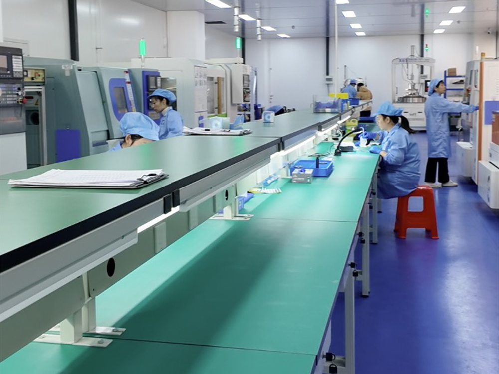
Standardized process parameters and automated production equipment reduce the manual variation that shows up later as feed-related chipping.
Step-by-Step: Setting and Verifying Blade Feed on an Automatic Dicing Machine
The following sequence treats feed as a controlled parameter with an owner, a record and a verification step — not as a machine default.
- Define the defect you are preventing. Before touching feed values, write down the acceptance criteria: maximum permitted edge chip size, kerf width tolerance and edge quality requirements for the specific device. Without a numeric target, feed optimization becomes subjective.
- Match the blade to the substrate family. Semiconductor wafer sawing, optical communication sawing, functional ceramic sawing and alloy material sawing each impose different load profiles. Select the blade family — for example a DZY Series wafer sawing blade, a DZR Series sawing blade, or a DZR-S Series slotted sawing blade — before setting feed.
- Start from the blade supplier's parameter window. Use the recommended feed range as the baseline, then validate on your own material stack, tape and machine, because the blade supplier's window is defined without your specific tape and chuck conditions.
- Tune feed and coolant together, never separately. Feed generates heat; coolant removes it. Increasing feed without checking nozzle position, flow and direction leaves heat in the bond, which produces glazing and the burnished edges associated with an over-slow cut.
- Use step feed or multi-pass where the substrate demands it. For thin or brittle substrates, distributing the cut across more than one pass lowers peak mechanical load per pass and widens the effective feed window.
- Verify with measurement, not with appearance. Inspect edge chipping, kerf width and blade wear at defined intervals within the lot. A recipe that looks acceptable at the first wafer can still drift by the tenth.
- Lock the recipe and record it per batch. Link the validated feed parameters to the blade batch number. Batch production data tracking is what allows you to distinguish a process drift from a blade batch change when a defect appears.
- Re-verify after every blade batch change. Run comparative testing of adjacent batches before releasing a new batch to full production. This single step prevents most lot-level defect events.
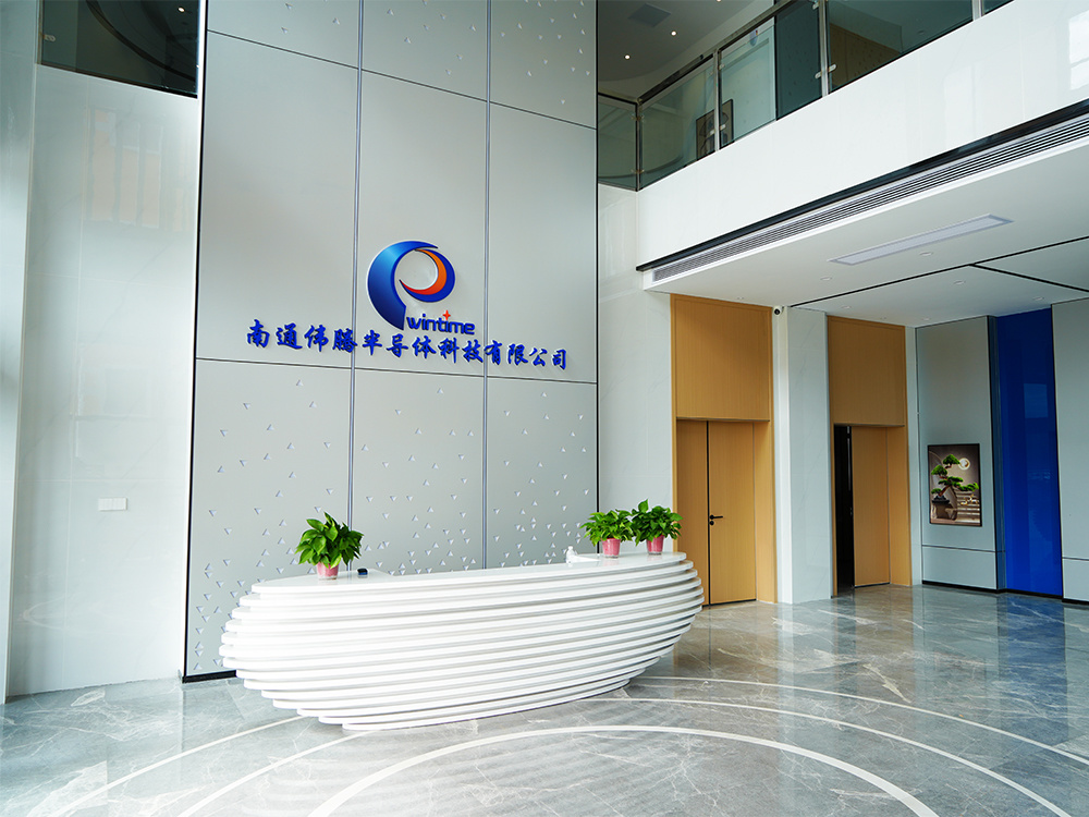
Batch quality files and traceable production records are what make a feed recipe reproducible across deliveries.
Where This Matters Most: Four Application Families
The mechanism is the same everywhere — load versus bond release — but the symptoms differ by application.
- Semiconductor wafer sawing. With 300 mm wafers and substrates below 50 µm, runout and feed spikes cause chipping and, in the worst case, blade breakage. Hubless construction and step feed are the primary countermeasures.
- Optical communication sawing. Optical communication and RF/optoelectronics represented 16% of dicing blade market share in 2024, and these devices are sensitive to edge quality rather than only to dimensional tolerance. Feed consistency matters more than peak speed.
- Functional ceramic sawing. Ceramics are brittle and generate abrasive debris that can load the kerf. Feed that is too slow allows debris to accumulate in the cut; feed that is too fast raises edge fracture risk.
- Alloy material sawing. Ductile alloys produce different chip behavior from brittle materials, so the feed window must be re-established rather than copied from a ceramic or silicon recipe.
Feed Defect Matrix: Symptom, Cause and Corrective Action
The table below converts feed symptoms into the likely cause and the specific corrective action to take on the line.
| Observed defect | Feed-related cause | Blade-side factor that amplifies it | Corrective action |
|---|---|---|---|
| Edge chipping along the street | Feed rate above the blade's working window | Kerf geometry not matched to street width | Reduce feed within window, verify blade runout, re-check kerf-to-street fit |
| Kerf drift or wandering cut | Inconsistent feed and index speed | Batch dimensional variation, hub runout | Lock feed parameters per recipe, verify blade thickness consistency batch by batch |
| Blade glazing, reduced cutting efficiency | Feed too slow, heat accumulating in the bond | Bond hardness not matched to material | Increase feed within the window, review resin versus metal bond selection |
| Random chipping appearing mid-lot | Feed unchanged but blade batch changed | Batch-to-batch variation in blade geometry | Run comparative testing of adjacent batches, request batch quality records |
| Particle-related defects near the street | Coolant and feed timing mismatch | Non-ESD-safe handling or packaging | Review anti-static handling and cleanroom class control |
| Blade breakage on thin substrate | Feed load spike during cut | Hub-type construction with runout on very thin wafers | Evaluate hubless blade construction for substrates below 50 µm |
What to Verify Before You Commit to a Blade Supply
Feed stability is only as durable as the supply behind it. The following verification points translate directly into whether a feed recipe will still be valid next quarter.
| Verification area | What to confirm | Reference point |
|---|---|---|
| Product classification | Whether the blade is classified and described consistently under recognized diamond tool categories | ISO 22180:2019 distinguishes CVD diamond-coated from monocrystalline and polycrystalline diamond tools |
| Quality system | Documented management system, SOP-based production and batch-level inspection | ISO 9001 quality management system with dedicated quality inspectors per batch |
| Bond type fit | Whether the bond matches the material hardness and the feed window you intend to run | Resin bond 42% and metal bond 33% of the 2024 dicing blade market, used for different material classes |
| Construction for thin wafers | Runout performance on substrates below 50 µm | Hubless dicing blades increasingly dominant for 300 mm wafer processing |
| Production capacity | Whether volume demand can be met without changing blade batches mid-campaign | 800,000+ pieces per month for standard specifications; 80,000+ pieces per month for customized and special-shaped products |
| Commercial terms | MOQ, delivery and payment structure before qualification begins | Standard models 100 pieces per order; customized models 500 pieces; delivery FOB/CIF; payment 30/70 |
| Acceptance criteria | How the incoming batch is verified | Pre-shipment test and third-party inspection (SGS) |
Feed Stability Is a Long-Term Supply Question, Not a One-Time Purchase
A dicing line does not fail because one blade was wrong. It fails because the blade that arrives in month nine is not the blade that was qualified in month one, while the feed recipe stays the same. That is why long-term supply relationships in precision dicing are built around consistency mechanisms rather than around unit price alone.
The mechanisms that protect a feed recipe over a multi-year campaign are concrete:
- Batch traceability. Every production batch carries a quality file that can be traced at any time, so a defect can be linked to a specific batch rather than to the whole supplier.
- Recall capability. If a batch is found to be out of specification, it can be identified and withdrawn before it reaches more production lines.
- Capacity headroom. WINTIME operates a 34,000 m² facility in Rugao with monthly capacity of over 800,000 pieces for standard specifications and over 80,000 pieces for customized and special-shaped products, alongside an annual output of more than 1 million dicing blades and a 35-engineer R&D team. Capacity headroom matters because it reduces the pressure to substitute blades from a different batch mid-campaign.
- Customization continuity. Custom and special-shaped blades are produced on the same controlled process basis as standard items, which keeps a validated feed window transferable from trial order to volume order.
- Global supply coverage. WINTIME exports to Southeast Asia, East Asia, North America and Europe, with an export ratio of 30%, and holds 2 patent technologies in precision cutting. For buyers sourcing across regions, this reduces the risk of region-specific specification drift.
For a production engineer, the practical summary is straightforward: treat blade feed as a controlled parameter, treat blade batch consistency as a supply-chain requirement, and treat both as part of the same long-term agreement with your blade partner.
FAQ: Feed, Compliance and Long-Term Sawing Blade Supply
Which standards and quality systems should a sawing blade supplier document?
Diamond tools, including sawing blades, are categorized under ISO 22180:2019, which distinguishes CVD diamond-coated tools from monocrystalline and polycrystalline types — a useful baseline for confirming that a product is described consistently. Beyond product classification, a supplier should be able to show a documented quality management system. WINTIME implements an ISO 9001 quality management system with standard operating procedures, assigns dedicated quality inspectors to track each production batch, and maintains a batch quality file that can be traced at any time, with recall of unqualified batches if a problem occurs.
What production capacity and customization capability does a stable blade supply require?
Capacity determines whether a validated feed recipe can be kept on the same blade batch across a campaign. WINTIME reports monthly production capacity of over 800,000 pieces for standard specifications and over 80,000 pieces for customized and special-shaped products, supported by a 34,000 m² facility, an annual output of more than 1 million dicing blades and an R&D team of 35 engineers. Customized blades are produced under the same standardized process parameters and automated equipment used for standard items, which is what allows a feed window validated on a trial order to remain valid in volume production.
What MOQ and purchasing terms should a buyer expect when qualifying a blade?
WINTIME applies an MOQ of 100 pieces per order for standard models, which is negotiable for long-term cooperative customers or bulk purchase plans. Customized models carry an MOQ of 500 pieces per order; for small-batch trial orders below 500 pieces, flexible MOQ adjustment is available with a slight price adjustment based on customization complexity. Delivery terms are FOB or CIF, and payment terms are 30/70.
How is a new blade validated before it is released to full production?
Validation combines supplier-side and buyer-side verification. On the supplier side, acceptance criteria include a pre-shipment test and third-party inspection (SGS). On the buyer side, the effective method is to run the candidate blade through the target feed recipe, measure edge chipping and kerf width against the defined acceptance criteria, and then run comparative testing of adjacent batches so that batch-to-batch consistency is confirmed before volume release — not after.
How do you keep a feed recipe stable over a long-term supply relationship?
Stability comes from documented batch control rather than from re-tuning the machine every delivery. The supplier-side controls are a batch production data tracking system that records process parameters, a traceable batch quality file with recall capability, and comparative testing between adjacent batches. The buyer-side controls are a locked feed recipe linked to the blade batch number, verification after every batch change, and a supply agreement that includes capacity headroom so blade batches are not substituted mid-campaign. WINTIME supports this through documented batch control, standard and customized capacity, and commercial terms that can be structured around long-term cooperation.
Conclusion: Feed Is a Controlled Parameter, Not a Machine Default
Large-scale die defects caused by blade feed are preventable, and the prevention is procedural rather than theoretical. Define the acceptance criteria, match the blade to the substrate, tune feed together with coolant, verify by measurement, lock the recipe to the blade batch, and re-verify at every batch change. Narrow kerf and ultra-thin blade bodies, anti-static cleanroom handling, tight dimensional control and hubless construction for thin substrates are what give that procedure enough margin to work.
When feed control and blade consistency are managed together, the result is not only fewer scrapped die — it is a dicing process that behaves the same in month twelve as it did in the qualification run.
Next Step: Validate the Feed Window on Your Own Material
WINTIME Semiconductor Technology Co., Ltd. supplies high-precision sawing blades for semiconductor wafer, optical communication, functional ceramic and alloy cutting, with documented batch control and standard or customized capacity.
Request a blade sample or a quotation, or download the product brochure to review specifications before your next feed-parameter trial.

WINTIME Semiconductor Technology Co., Ltd., Rugao City, Jiangsu Province — sample and quotation requests are handled directly by the technical team.
Have Questions or Need More Details?
Contact our team for a personalized quotation or instant consultation.
Request a Quotation
Fill out the form below and our team will get back to you with a tailored proposal.
WhatsApp Direct Chat
Prefer to chat in real-time? Message us on WhatsApp for instant assistance & quick answers.
- Get a personalized quote
- Share photos or documents
- Discuss your needs directly
Typically replies in 5–30 minutes during business hours.