
Sawing Blade Application Handbook: Turning Designs into Precision Alloy Components
Precision alloy components rarely fail because of the drawing. They fail at the cut. This handbook explains how an approved alloy component design becomes a production-ready cutting process: the blade envelope, the site conditions, the step-by-step setup, and the dry and wet operating modes that deliver high-efficiency cutting and stable dimensional control when fed by a high-speed spindle. It is published by WINTIME Semiconductor Technology Co., Ltd., a manufacturer of high-precision wafer-level cutting blades, and it is organised around project benchmarks in Korea, Singapore, and China.
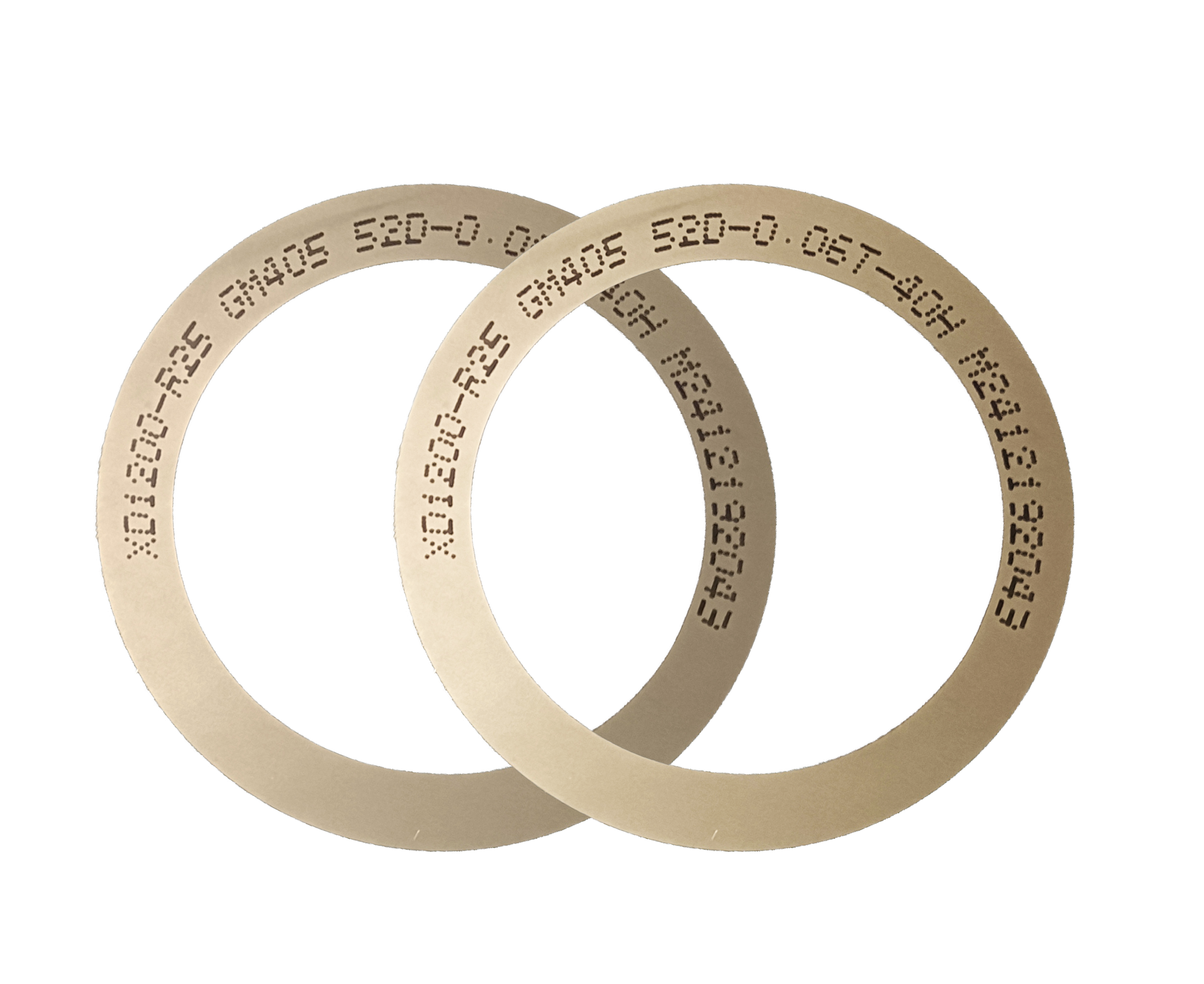
Problem Definition: Why Alloy Component Cutting Is a Project Problem, Not a Blade Problem
A precision alloy component project begins with a drawing that specifies a tolerance, a surface requirement, and a set of edge-quality expectations. What the drawing does not specify is how those expectations survive contact with a spindle turning at 30,000 to 60,000 rpm.
Three project-level constraints decide whether the design is manufacturable at all:
- Kerf budget. Every cut consumes material. On a narrow alloy feature or a tightly spaced pattern, kerf width and blade thickness — the WINTIME Sawing Blade family spans an 8 μm to 50 μm thickness range — directly change how many good parts come out of one workpiece.
- Edge integrity. Precision alloy parts are judged on chipping, burrs, micro-cracking, and heat-affected zones. The design target for this product family is narrow kerf, low chipping, and stable dimensional control.
- Stability across the run. A cutting accuracy of ±0.002 mm matters only if it holds from the first part to the last. Blade hardness of HRC 65–70 and bond integrity are what keep that accuracy inside the window.
The project question is therefore not "which blade is sharpest". It is: which blade, operated in which mode, on which site conditions, keeps all three constraints inside tolerance for the entire lot.
Industry Background: Where Precision Alloy Cutting Sits Today
Precision alloy cutting sits inside a much larger diamond-tool economy that is still expanding. The global diamond saw blade market was valued at approximately USD 8.60 billion in 2025 and is expected to reach USD 10.16 billion by 2032, according to Maximize Market Research. Within that, the wafer dicing blade segment alone was valued at USD 1.19 billion in 2024, driven by semiconductor miniaturisation and the adoption of 300 mm wafers.
Bond selection is the clearest structural signal in this market. In 2024, resin bond blades held a 42% share of the dicing blade market, while metal bond blades accounted for 33% — the type typically used for harder materials such as SiC, and the reason metal-bond constructions matter in alloy component work.
Application demand is shifting at the same time. Optical communication and RF/optoelectronics applications accounted for 16% of dicing blade market share in 2024, a value of USD 69.9 million, driven by 5G infrastructure expansion. On the equipment side, hubless blade designs are becoming increasingly dominant in 300 mm wafer processing because of their superior stability and reduced runout on thinner substrates below 50 µm.
Two reference points anchor compliance and supplier evaluation. Diamond tools, including sawing blades, are categorised under ISO 22180:2019, which distinguishes between CVD diamond-coated and monocrystalline or polycrystalline types. And the competitive field for high-precision semiconductor cutting blades includes DISCO Corporation, Tokyo Seimitsu (Accretech), Advanced Dicing Technologies (ADT), and Asahi Diamond, according to Credence Research.
WINTIME Semiconductor Technology Co., Ltd. operates in the same precision cutting blade category. The company was established in 2020, integrates research, development, production, and sales of high-precision wafer-level cutting blades, employs 35 R&D engineers, and runs a 34,000 m² facility with an annual output of 1 million pieces and an export ratio of 30% across Southeast Asia, East Asia, North America, and the EU.
The Cutting Envelope: What a Precision Alloy Sawing Blade Is Built to Do
WINTIME's Sawing Blade platform (model SB-001) is engineered to deliver high-precision wafer cutting, ultra-thin slicing, narrow kerf, low chipping, high-efficiency cutting, and stable dimensional control. Those outcomes are produced by a defined set of physical and process parameters, not by a single specification.
| Project requirement | Documented specification |
|---|---|
| Kerf and thickness control | Blade thickness range 8 μm – 50 μm |
| Ultra-thin capability | ≤9 μm, achieved in the completed "Ultra-thin Wafer D Blade" project |
| Dimensional accuracy per part | Cutting accuracy ±0.002 mm |
| Spindle compatibility | 30,000 – 60,000 rpm |
| Blade wear resistance | Hardness HRC 65–70 |
| Bond architecture | Resin bond / metal bond |
| Abrasive | Diamond superabrasive |
| Bond matrix and base | Resin or metal bond matrix on a high-strength steel base |
| Debris evacuation | Chip removal rate ≥1.2 mm³/s |
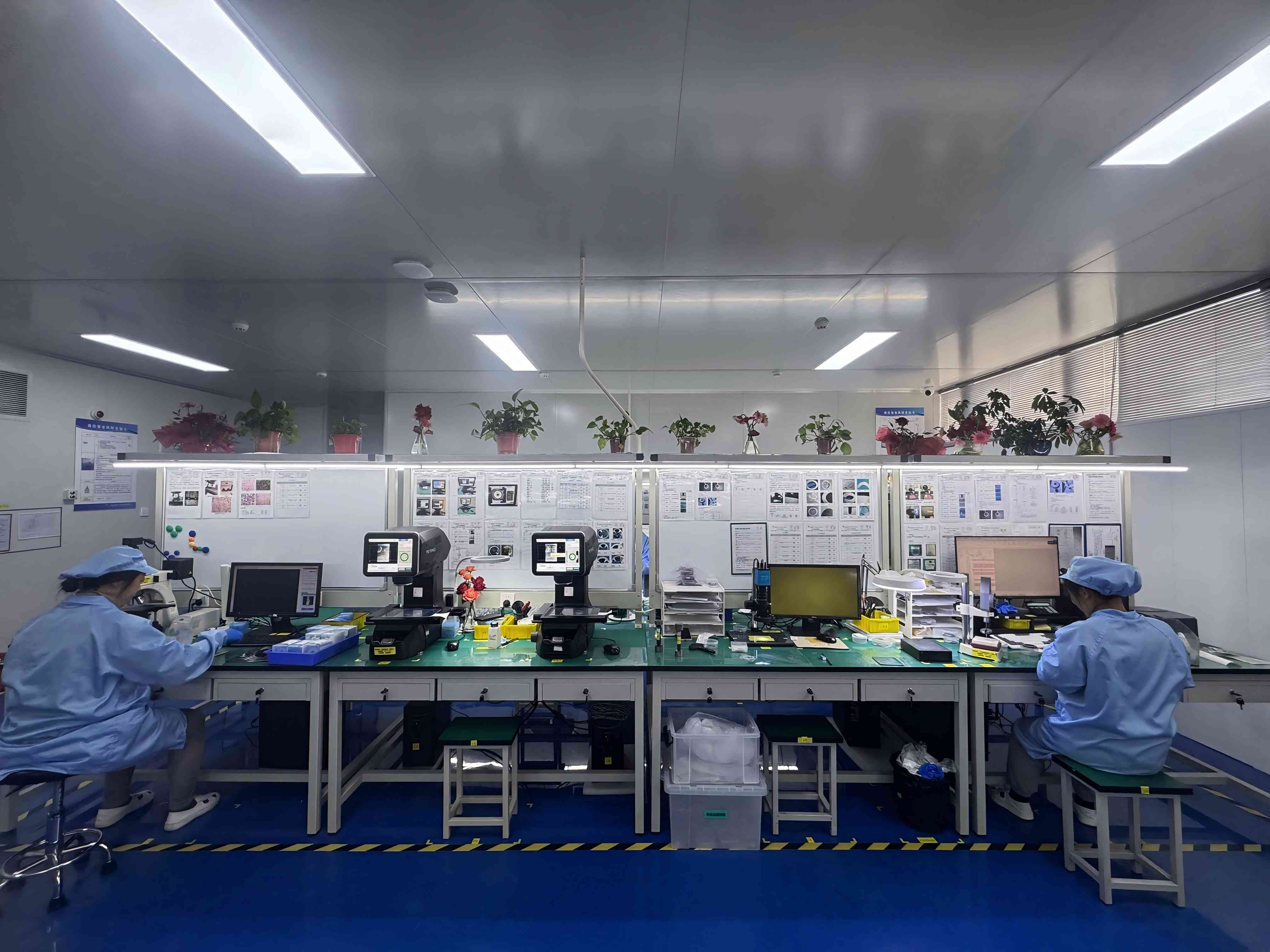
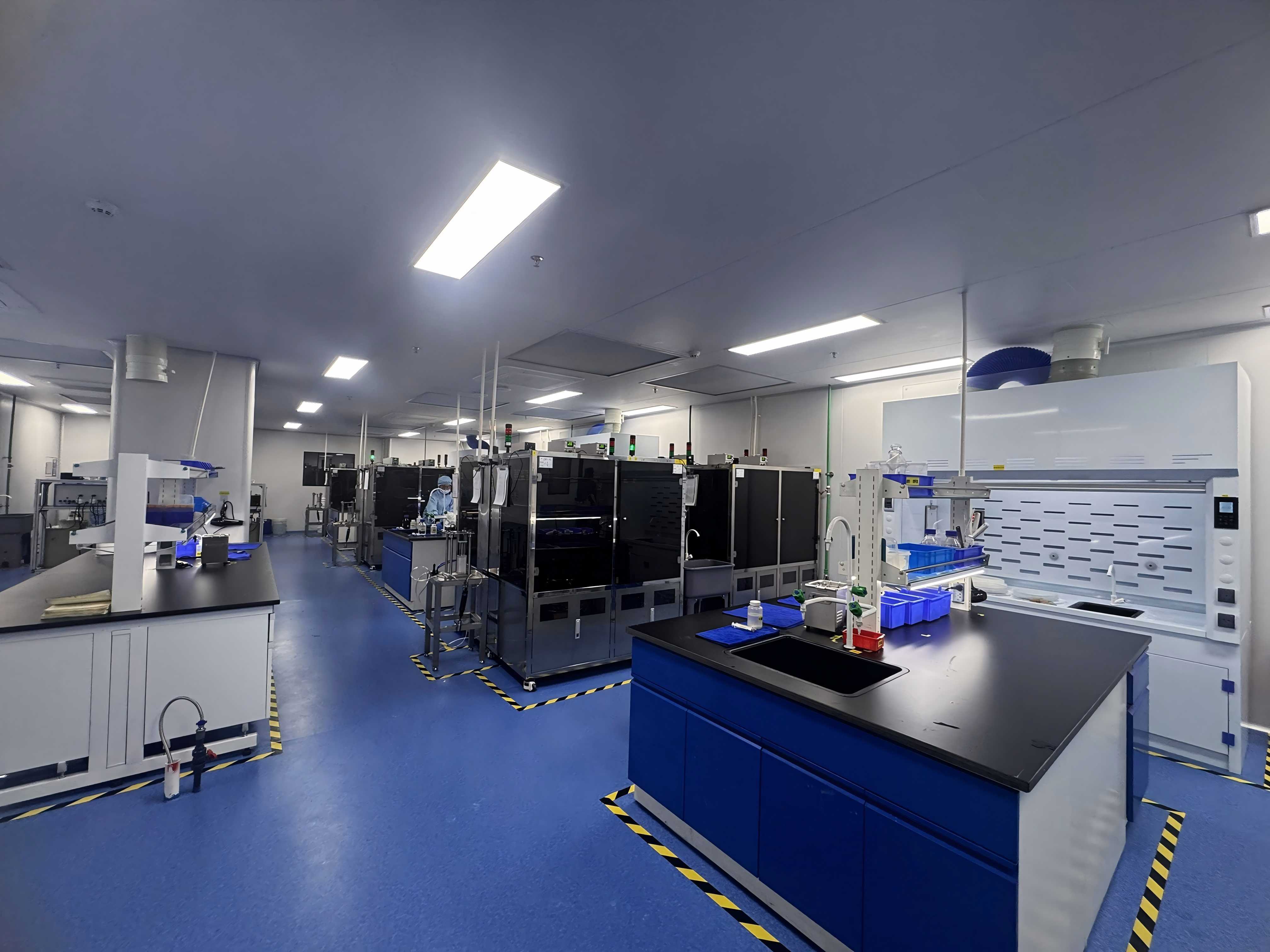
| Site conditions | Class 100/1000 clean room, constant temperature 22±2 °C, constant humidity 45%–55%, dust-free, anti-static |
| Cutting modes | High-speed spindle rotating cutting, dry/wet cutting, automatic dicing machine continuous operation, precision feeding cutting |
| Special requirements | High wear resistance, low cutting loss, anti-static, high dimensional accuracy, long service life, stable mass production |
The construction catalogue covers Diamond, Precision, Semiconductor, Circular, Hubbed, Hubless, Flanged and Serrated Sawing Blades, plus the DZY Series Wafer Sawing Blade, DZR Series Sawing Blade, and DZR-S Series Slotted Sawing Blade, alongside SZ Series resin-bond and JS Series metal-bond constructions. Across the wider industry, blade construction routes generally fall into resin bond, metal bond, and electroformed (electrodeposited nickel–diamond) families; the WINTIME catalogue covers the resin-bond and metal-bond routes.
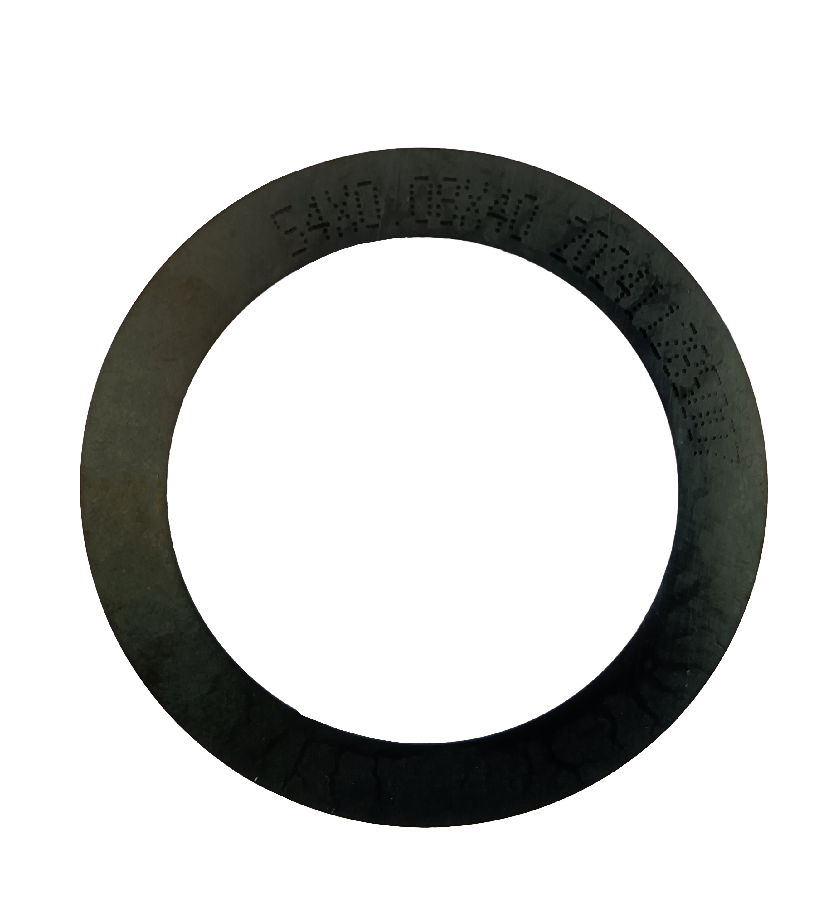
Substrate families this envelope is designed to serve
The platform is designed for applications across semiconductor manufacturing, semiconductor packaging, optical communication, new functional materials, functional ceramics, and alloy materials. That list matters for alloy component projects because the same blade envelope has to serve workpieces with very different hardness and thermal behaviour — which is why bond type and thickness selection, not blade brand alone, determines the process outcome.
Step-by-Step Breakdown: From Design File to Qualified Part
The sequence below is the order in which a precision alloy component cutting project should be resolved. Skipping a step typically shows up later as chipping, kerf drift, or blade breakage.
- Design review and kerf mapping. Convert the drawing into a cut plan: which features are separated, in what order, and how much material each cut removes. Blade thickness must be chosen against the narrowest feature spacing, not against the thickest part of the component.
- Workpiece characterisation. Confirm the material family — alloy materials, functional ceramics, optical materials, or semiconductor substrates — because hardness and thermal response determine whether a resin bond or metal bond is appropriate.
- Blade selection. Fix bond type (resin or metal), blade thickness within the 8–50 μm window, blade series (DZY, DZR, DZR-S slotted, hubless, flanged, or hubbed), and the diamond grain size and concentration appropriate to the material.
- Site condition verification. Confirm Class 100/1000 clean room status, that temperature holds at 22±2 °C and humidity at 45%–55%, that anti-static measures are in place, and that the spindle can operate in the 30,000–60,000 rpm range.
- Operating mode decision. Select dry or wet cutting for the specific material and feature set (see the comparison section below), and confirm that the chosen mode is compatible with the automatic dicing machine being used.
- Mounting and workholding. Mount the workpiece on the correct carrier and release film so that the component stays flat and dimensionally stable through the cut and can be demounted without mechanical stress or residue.
- Feed and parameter optimisation. Establish precision feeding inputs that keep the blade inside its chip-removal capacity of ≥1.2 mm³/s without stalling the cut or loading the bond.
- Verification and metrology. Measure kerf width, part dimensions against the ±0.002 mm accuracy target, edge chipping, and burr formation on the first parts before releasing the lot.
- Continuous-run stability check. Track blade wear against parts produced across a continuous run to confirm stable dimensional control rather than a good first article.
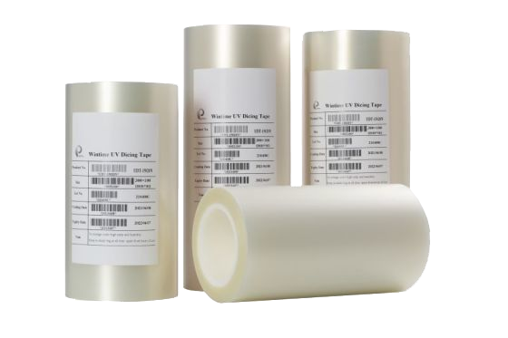
Use Cases: Project Benchmarks in Korea, Singapore, and China
WINTIME's application data positions this blade platform in CN, JP, KR, SG, MY, US, and DE. The three markets below are presented as requirement benchmarks — the site conditions and project types a new alloy component project is measured against — rather than as named customer references.
| Benchmark market | Site and process baseline | Representative project type | Blade attributes that carry the project |
|---|---|---|---|
| Korea (KR) | Class 100/1000 clean room; 22±2 °C; 45%–55% RH; dust-free; anti-static; high-speed spindle | Semiconductor package cutting; precision alloy component cutting | 8–50 μm thickness window; ±0.002 mm accuracy; HRC 65–70; resin or metal bond |
| Singapore (SG) | Class 100/1000 clean room; 22±2 °C; 45%–55% RH; dust-free; anti-static; high-speed spindle | Optical device cutting; precision alloy component cutting | Narrow kerf; low chipping; hubless stability with reduced runout on thin parts |
| China (CN) | Class 100/1000 clean room; 22±2 °C; 45%–55% RH; dust-free; anti-static; high-speed spindle | Precision alloy component cutting; ultra-thin slicing and wafer dicing | ≤9 μm ultra-thin capability; high wear resistance; stable mass production |
Trade data supports the regional demand pattern behind these benchmarks. China's exports of cutting blades to Vietnam, India, and South Korea grew significantly between 2024 and 2025, with Vietnam increasing by USD 18 million and India by USD 12 million, according to the Observatory of Economic Complexity.
Adjacent use cases the same envelope covers
Because the platform is designed across semiconductor manufacturing, semiconductor packaging, optical communication, new functional materials, functional ceramics, and alloy materials, alloy component projects frequently share tooling and site conditions with neighbouring applications: ultra-thin wafer processing, optical device cutting, ceramic substrate cutting, wafer dicing and scribing, and semiconductor package cutting. That overlap is useful in practice — a project that outgrows a single material family can usually stay on the same blade platform and site set-up.
Dry and wet cutting as two documented operating modes
Dry cutting and wet cutting are both documented operating modes for this platform, alongside high-speed spindle rotating cutting, automatic dicing machine continuous operation, and precision feeding cutting. The choice is not a preference; it is a function of how much heat the alloy feature can tolerate, how easily debris clears the kerf, and what the surrounding process flow allows.
Comparison Table: Matching Bond, Mode, and Site Conditions to the Project
Use the comparison below as a decision framework. Every row is anchored to a documented capability or site condition rather than to an assumed performance ranking.
| Decision factor | Wet cutting | Dry cutting |
|---|---|---|
| Heat management at the kerf | Liquid coolant carries heat away from the cut zone, which generally reduces thermal load on the bond and the workpiece. | Heat remains in the blade and component, so spindle speed and precision feeding must be managed more tightly within the 30,000–60,000 rpm range. |
| Debris and chip evacuation | Coolant flow helps clear debris and supports the documented chip removal rate of ≥1.2 mm³/s. | Relies on blade exposure, feed control, and extraction rather than fluid transport. |
| Edge condition on alloy parts | Generally lowers the risk of thermal marking and burr formation on alloy features. | Higher sensitivity to parameter windows; edge quality is proven by trial rather than assumed. |
| Cleanroom and anti-static fit | Compatible with Class 100/1000 conditions and the 22±2 °C, 45%–55% RH baseline; introduces liquid handling to the flow. | Avoids liquid handling entirely, which can simplify the flow where liquid contact is undesirable. |
| Production continuity | Suits continuous operation on automatic dicing machines where coolant supply is stable. | Suits setups where the process window has already been locked by simulation and validation. |
Verification before commitment: the quality-control sequence
Before a blade specification is released for an alloy component project, WINTIME's quality control applies four checks: geometric dimension inspection using a vernier calliper and laser diameter gauge; hardness and wear resistance testing on a material testing machine; dynamic balance detection on a high-speed dynamic balance tester; and cutting performance simulation on the actual material. For a buyer, that sequence is also the checklist to replicate on the receiving line.
FAQ: Precision Alloy Component Cutting
What site and compliance conditions should be confirmed before a precision alloy cutting project starts?
The documented working environment for this application is a Class 100/1000 clean room with a constant temperature of 22±2 °C, constant humidity of 45%–55%, dust-free and anti-static conditions, and a high-speed spindle. Where the design requires it, the special requirements are an ultra-thin blade thickness of ≤9 μm, high wear resistance, low cutting loss, anti-static performance, high dimensional accuracy, long service life, and stable mass production. For blade classification and audit trails, diamond tools including sawing blades fall under ISO 22180:2019, which distinguishes CVD diamond-coated types from monocrystalline and polycrystalline types.
Can a sawing blade be customised to a specific alloy material and dicing machine?
Yes. WINTIME operates OEM, ODM, and customised production, with a customisation scope covering blade diameter, thickness and spindle hole size; bond type (metal bond or resin bond); diamond abrasive grain size and concentration; coating for anti-rust, heat-dissipation or wear resistance; cutting performance targets such as cutting speed and service life; export and special packaging; and special-shaped, non-standard blade sizes. The standard Sawing Blade envelope is 8 μm to 50 μm thickness, ±0.002 mm cutting accuracy, 30,000–60,000 rpm spindle speed, HRC 65–70 hardness, a resin or metal bond, and a chip removal rate of ≥1.2 mm³/s. Technical support for cutting process matching and equipment adaptation is included.
What actually drives the cost of a precision alloy component cutting project?
Unit blade price is usually the smallest number in the calculation. The larger cost drivers are kerf width, because kerf determines how much alloy material each part consumes; blade life and the changeover frequency it implies; breakage and scrap rate on thin or brittle features; whether the process runs wet or dry and what consumables that adds; and the inspection time needed to demonstrate ±0.002 mm accuracy across a lot. The practical comparison is total cutting cost per good part, measured over a continuous run, not price per blade.
How should a sample validation run be structured?
Start with a small controlled lot: the minimum order quantity is 50 pieces for standard products and 300 pieces for customised products, so a validation run is a realistic first step, and standard products ship in 2–5 working days, which keeps the loop short. WINTIME's quality control sequence — geometric dimension inspection with vernier calliper and laser diameter gauge, hardness and wear resistance testing on a material testing machine, dynamic balance detection on a high-speed dynamic balance tester, and cutting performance simulation on the actual material — defines what to replicate on your own line: measure kerf width and part dimensions, inspect chipping and burr formation, track blade wear against parts cut, and confirm stability over continuous operation.
What lead time, capacity, and after-sales support can a project plan around?
Standard products are quoted at 2–5 working days, while customised orders run 10–25 working days with adjustable schedules for large orders. Monthly capacity is 800,000+ pieces for standard specifications and 80,000+ pieces for customised and special-shaped products, against an annual output of 1 million pieces. After-sales coverage includes technical support for cutting process matching and equipment adaptation, quality problem investigation and solution within 48 hours, customised after-sales service for bulk procurement customers, long-term supply guarantee and inventory support, product application training for new customers, and replacement or compensation for defective products caused by quality problems. To move from benchmark to a validated process, request a sample evaluation or quotation by emailing shenxiangfei@ntwintime.com, calling +86 13851530812, or messaging +8618888053207 on WhatsApp.
Conclusion: The Design Is Only as Good as the Cut
Turning a precision alloy component design into qualified parts comes down to four decisions made in the right order: match blade thickness and bond type to the workpiece and the kerf budget; confirm the site can hold Class 100/1000 conditions with anti-static control and a spindle capable of 30,000–60,000 rpm; choose between dry and wet cutting based on thermal load and debris clearance rather than habit; and prove the process with a small validation lot before committing volume. The verified envelope for this platform — 8–50 μm thickness, ≤9 μm ultra-thin capability, ±0.002 mm accuracy, HRC 65–70, chip removal ≥1.2 mm³/s — is what makes those decisions measurable rather than subjective.
Next Step: Sample and Specification Review
Send your alloy component drawing and dicing machine details, and the WINTIME team will return a blade recommendation — bond type, thickness, series, and operating mode — plus a sample plan for validation.
Email: shenxiangfei@ntwintime.com · Tel: +86 13851530812 · WhatsApp: +8618888053207
Website: en.wintime.net.cn · Brochure: Download the full Sawing Blade product brochure
Have Questions or Need More Details?
Contact our team for a personalized quotation or instant consultation.
Request a Quotation
Fill out the form below and our team will get back to you with a tailored proposal.
WhatsApp Direct Chat
Prefer to chat in real-time? Message us on WhatsApp for instant assistance & quick answers.
- Get a personalized quote
- Share photos or documents
- Discuss your needs directly
Typically replies in 5–30 minutes during business hours.