
Sawing Blade Best Practices in Optical Communications

Cutting optical components is governed by a short list of repeatable practices rather than by a single blade specification. Yield in optical communications dicing normally depends on four decisions: matching the bond and geometry to the optical material, holding the cut inside a class 100/1000 cleanroom envelope, controlling static at every interface between blade, workpiece and equipment, and keeping the cut straight and stable so that kerf and edge condition stay inside the optical alignment budget. Supplier selection, sample validation and lead-time planning follow from those four decisions.
This article sets out those practices in the order they matter on the production floor, then maps them to the blade formats and configuration levers produced by WINTIME Semiconductor Technology Co., Ltd., a manufacturer of high-precision dicing blades founded in 2020 and based in Rugao City, Jiangsu Province. The purpose is practical: when chipping, kerf drift, contamination or blade breakage appears on an optical cutting line, a ranked practice list tells the process engineer what to correct first.
Problem Definition: Why Optical Cutting Punishes a Generic Blade Recipe
Mechanical cutting tolerates defects that optical cutting does not. A small chip on an industrial part is often cosmetic; the same chip on a glass, fused silica or lithium niobate surface becomes a scattering site, a crack initiation point, or a shift in the position of an optical axis. In optical communication modules and substrates, the cut is part of the mechanical reference for the optical path, so edge quality and dimensional stability are functional requirements rather than finishing details.
Four failure modes dominate the scrap and rework reports on optical dicing lines:
- Edge chipping and micro-cracks. Brittle optical materials propagate damage from the cut edge. A crack that is invisible at inspection can open during thermal cycling, soldering or subsequent lapping, and the failure appears at a later assembly step where traceability is harder.
- Contamination. Debris from the bond, the workpiece or the coolant loop deposits on freshly cut surfaces and sidewalls. In optical assembly, particle contamination on a cut face is a defect, not a cleaning problem to be solved later.
- Static-driven particle attraction. In low-humidity cleanroom environments, charge accumulating on blades, chucks, tapes and handling tools pulls airborne particles onto exactly the surfaces that must remain clean. Static control is therefore a particle-control measure in optical dicing, not only an electronics-protection measure.
- Kerf drift, runout and wall angle. A blade that is not stable laterally produces slanted walls, varying kerf and, in array work such as V-groove or fibre-array cutting, pitch error that accumulates across the part.
These failures rarely have a single cause. Most optical cutting problems trace back to applying a general-purpose blade and recipe to a material with different fracture behaviour, then compensating downstream with slower feeds, extra cleaning or additional inspection. A best-practice programme reverses that sequence: define the cut and the environment first, then specify the blade.
Industry Background: A Small, Specialised Slice of the Dicing Market
Optical work is a modest but strategically important part of dicing demand. The global wafer dicing blade market was valued at USD 1.19 billion in 2024, driven by semiconductor miniaturisation and the adoption of 300 mm wafers (Market Research Intel). Optical communication and RF/optoelectronics applications accounted for 16% of that market in 2024, equivalent to USD 69.9 million, with 5G infrastructure expansion named as the growth driver (Intel Market Research). At the wider tool level, the global diamond saw blade market was valued at approximately USD 8.60 billion in 2025 and is expected to reach USD 10.16 billion by 2032 (Maximize Market Research).
Published market figures should be read with caution, because sources scope the category differently. For the 2024 dicing blade market, Intel Market Research reports USD 1.31 billion while Dicing Blade Market Insights reports USD 0.437 billion — a gap explained largely by whether consumables or equipment are counted. Buyers evaluating an optical blade programme are better served by configuration and process-support evidence than by market sizing.
Three technical and supply facts are more directly useful in an evaluation:
- Bond mix. Resin bond blades held a 42% share of the dicing blade market in 2024, while metal bond blades — used for harder materials such as SiC — accounted for 33% (market.us).
- Hubless formats. Hubless dicing blades are increasingly dominant for 300 mm wafer processing because of superior stability and reduced runout on substrates thinner than 50 µm (Semiconductor Equipment Market Data).
- Standards coverage. Diamond tools, including sawing blades, are categorised under ISO 22180:2019, which distinguishes CVD diamond-coated types from monocrystalline and polycrystalline types (ISO).
Supply is international. Leading competitors in the high-precision semiconductor dicing blade market include DISCO Corporation, Tokyo Seimitsu (Accretech), Advanced Dicing Technologies (ADT) and Asahi Diamond (Credence Research). Chinese blade exports to Vietnam grew by USD 18 million and to India by USD 12 million between 2024 and 2025 (OEC). The practical implication is that multiple qualified sources exist, and what separates them for optical work is configuration control, cleanroom-compatible handling and process support rather than brand recognition alone.
Detailed Solution: What Can Be Specified for an Optical Cutting Blade
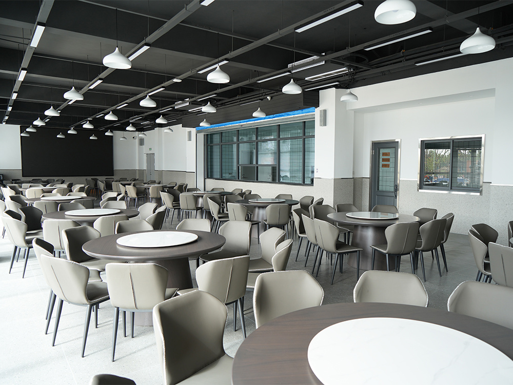
WINTIME Semiconductor Technology Co., Ltd. is a Chinese manufacturer of high-precision dicing blades, cutting tapes and cutting solutions, established in 2020, operating a 34,000 m² facility in Rugao City, Jiangsu Province, with 35 research and development engineers, 100 employees and an annual output of one million pieces. Its production model covers OEM, ODM and customised production, with specifications adapted to different cutting materials and working conditions.
For optical communications cutting, seven configuration levers can be set per application:
- Blade diameter, thickness and spindle hole size
- Bond type — metal bond or resin bond
- Diamond abrasive grain size and concentration
- Coating — anti-rust, heat-dissipation or wear-resistant
- Cutting performance targets — cutting speed and service life
- Packaging, including special packaging for export
- Special-shaped blade customisation for non-standard sizes
The formats most often involved in optical communications work are hubless sawing blades, DZY Series wafer sawing blades, DZR Series sawing blades, DZR-S Series slotted sawing blades and electroforming hard sawing blades, together with dedicated configurations for functional ceramic sawing and alloy material sawing. In practice the geometry and bond are quoted per application, because the same nominal part can require a different grain size or bond depending on whether the workpiece is glass, a functional ceramic such as AlN or Al2O3, a brittle crystal, or an alloy carrier.
Evidence to request at supplier level. Configuration claims are only useful if they are verified. In WINTIME's quality control process, geometric dimensions are checked with a vernier calliper and a laser diameter gauge, hardness and wear resistance are tested on a material testing machine, and dynamic balance is measured on a high-speed dynamic balance tester, followed by a cutting performance simulation test on the actual material. For an optical programme, those records should be requested for the specific lot configuration, not only for the product family.
Step-by-Step Breakdown: Seven Best Practices, Ranked
The ranking reflects the order in which each practice influences optical yield. Changing practice 1 alone rarely solves a chipping problem; skipping practice 3 or 4 usually means no blade change will hold its result.
1. Define the cut before specifying the blade
A blade specification without a cutting specification is guesswork. Before any blade is quoted for optical work, document the workpiece material and thickness, the target feature size and tolerance, the cut length per part and per wafer, the cleanliness class of the downstream area, and the processes that follow dicing — bonding, soldering, polishing or coating — because those processes propagate micro-cracks that were created at the cut. The deliverable is a one-page cutting specification attached to the purchase order, so that the blade geometry, bond and grain in the quotation can be traced back to a requirement.
2. Match bond and abrasive to the optical material
Bond choice is the first technical lever. Resin bond remains the mainstream dicing option with 42% of the 2024 market, and is generally used where edge quality on glass and ceramic is the priority; metal bond, at 33% of the market and used for harder materials such as SiC, is chosen where bond wear resistance and blade life are the limiting factors. Diamond grain size and concentration form the second lever: finer grain supports edge quality, coarser grain supports throughput. Coating selection — anti-rust, heat-dissipation or wear-resistant — is the third, and matters most where the cut generates heat close to a temperature-sensitive optical assembly.
3. Fix the cleanroom envelope around the cut
Optical dicing is normally performed in class 100/1000 environments, and the practical work is to stop the environment from degrading during production. That means verifying filtration and airflow over the tool, controlling gowning discipline, and treating blade storage as part of the process: blades should not be stored open beside particle-generating operations. Coolant quality belongs here too, because the deionised water loop carries particles directly to the cut face. Export-grade protective packaging matters for the same reason — a blade that is clean at dispatch should still be clean when it reaches the tool.
4. Control static at every interface
Static control in optical cutting is primarily a contamination control measure. Ground the spindle and chuck, verify continuity at every blade changeover, use ionisation at load and unload positions, and avoid insulating films or tapes that trap charge on the workpiece. The check should be written into the setup sheet rather than left to operator judgement, because a static problem shows up as particles on a cut face rather than as an immediate machine fault.
5. Hold a straight cut with measured stability
Straightness is a stability result, not a blade-only property. Confirm mounting and flange condition, verify runout after every blade change, and confirm dynamic balance, which is one of the four checks in WINTIME's quality control sequence. Measure kerf on the first part and at defined intervals through the run, keep blade exposure inside the qualified window, and use step cutting where the material is brittle enough to require it. When kerf drift appears, the useful question is whether drift correlates with blade life, coolant flow or spindle balance — not simply which blade to buy next.
6. Manage coolant, debris and blade exposure
Debris control determines whether a good cut stays good. Align the coolant nozzle to the cut entry point rather than the blade centre, keep flow and filtration stable, and prevent removed material from being redeposited on freshly cut sidewalls. Blade exposure and dressing practice keep the blade open and cutting rather than rubbing, which is a common cause of heat-related damage on thin optical parts.
7. Qualify by inspection and lock the recipe
The last practice is the one that makes the previous six repeatable: inspect edge quality and chipping, check the cut dimension, examine wall angle on a cross-section where the geometry matters, and confirm cleanliness before the part moves downstream. Record blade life and kerf trend so the next lot starts from data. Where a problem does appear, WINTIME's after-sales process includes technical support for cutting process matching and equipment adaptation, quality problem investigation within 48 hours, application training for new customers, and a long-term supply guarantee with inventory support.

Best-Practice Priority Table: What to Fix First
| Rank | Practice | What to verify before moving on |
|---|---|---|
| 1 | Cut specification defined | Material, thickness, target feature size and tolerance, cut length, cleanliness class and downstream processes documented on the purchase order. |
| 2 | Bond and abrasive matched | Bond type (resin or metal) and diamond grain size and concentration selected against the material, with coating choice recorded. |
| 3 | Cleanroom envelope fixed | Class 100/1000 environment verified, gowning controlled, blade storage and coolant loop treated as part of the process. |
| 4 | Static control in place | Grounded spindle and chuck, continuity checked at changeover, ionisation at load/unload, no charge-trapping films on product. |
| 5 | Straight cut and stability | Runout checked at each blade change, dynamic balance confirmed, kerf measured per lot, blade exposure inside the qualified window. |
| 6 | Coolant and debris controlled | Nozzle aligned to cut entry, stable flow and filtration, no redeposition on cut sidewalls, correct dressing practice. |
| 7 | Inspection and recipe lock | Edge and chipping inspection, dimension check, cross-section where wall angle matters, cleanliness confirmed, blade life trend recorded. |
Use Cases: Where These Practices Apply
Optical module substrates and submounts
Functional ceramic substrates such as AlN and Al2O3, silicon submounts and similar carriers are singulated to tight dimensions because they set the position of optical components. The dominant risks are chipping at the cut edge and contamination on the mounting face, which places the priority on bond selection and cleanroom handling rather than on throughput.
PLC splitters, V-groove arrays and fibre-array glass parts
Array cutting multiplies pitch error: a small kerf deviation at the first cut can put the final channel outside tolerance. Straightness and kerf stability are the governing requirements here, supported by per-lot kerf measurement and controlled blade exposure.
Fibre ferrules and capillaries
Ceramic ferrules and capillaries require a straight cut with a clean end face. Because these parts are small and often handled individually, static control and blade storage discipline have an outsized effect on particle counts.
Lithium niobate and other brittle optical crystals
Brittle crystals respond badly to a rubbing blade. The practical measures are finer diamond grain, step cutting where the geometry allows, and inspection that looks for micro-cracks rather than only for visible chips.
Silicon photonics and thin 300 mm substrates
Thin wafers make hubless formats the mainstream choice, and blade thickness becomes a limiting factor. WINTIME's ultra-thin wafer dicing blade project achieved a blade thickness below 9 µm in the process, and the company is among the few domestic manufacturers able to mass-produce at that level. The applicable controls are hubless blade stability, dynamic balance, and a coolant strategy that keeps a thin blade cutting rather than rubbing.
Alloy housings, carriers and laser diode components
Alloy material cutting shifts the priorities towards bond wear resistance, blade life and coating selection — including anti-rust and heat-dissipation coatings — because metal workpieces load the bond differently from brittle optical materials.

Comparison Table: Blade Formats and Configuration Levers for Optical Cutting
The table below maps the blade formats used in optical communications cutting to their typical task and to the configuration levers that must be confirmed before quotation. It lists what can be specified, not fixed specifications — final geometry, bond and grain are defined per application.
| Blade format | Typical role in optical communications cutting | Configuration levers to confirm |
|---|---|---|
| Hubless sawing Blade | Thin wafer and thin substrate dicing where lateral stability and low runout are required; hubless formats are increasingly dominant in 300 mm processing on substrates below 50 µm. | Diameter, thickness and spindle hole size; bond type; diamond grain size and concentration; coating. |
| DZY Series wafer sawing Blade | Wafer-level singulation of optical device wafers and photonic dies, where the cut sets the die edge condition. | Geometry and spindle hole; bond type; grain size and concentration; cutting performance targets (speed, service life). |
| DZR Series sawing Blade | Precision dicing of optical substrates, functional ceramics and alloy carriers across mixed production lines. | Bond type; grain size and concentration; coating; export packaging. |
| DZR-S Series slotted sawing Blade | Slotted and profiled cutting where a defined slot geometry is required rather than a simple through-cut. | Special-shaped (non-standard size) customisation; slot geometry; spindle hole size. |
| Electroforming hard sawing Blade | Hard and brittle workpieces where abrasive retention and bond behaviour limit blade life. | Bond type; diamond concentration; coating; cutting performance targets. |
| Functional ceramic configuration | AlN and Al2O3 submounts, ceramic ferrules and capillaries used in optical modules. | Bond type; grain size; geometry; protective and export packaging. |
| Alloy material configuration | Metal housings, carriers and components around laser diode and optical module assemblies. | Bond type; anti-rust, heat-dissipation or wear-resistant coating; geometry. |
FAQ: Optical Communications Sawing Blade Decisions
Which standards and cleanroom conditions apply to sawing blades used in optical communications?
Diamond tools, including sawing blades, are categorised under ISO 22180:2019, which distinguishes CVD diamond-coated types from monocrystalline and polycrystalline types, so a supplier's product documentation should be mappable to that classification. On the process side, optical cutting is normally run in class 100/1000 cleanroom conditions, with the environment verified at the tool rather than only at the room level. Buyers should ask for the verification records behind the blade configuration: geometric dimension inspection, hardness and wear resistance testing, dynamic balance detection and a cutting performance simulation test on the actual material.
Can one manufacturer supply hubless, slotted, electroformed and ceramic-cutting blades together with process support?
Yes, where the supplier runs a customised production model rather than a fixed catalogue. WINTIME covers OEM, ODM and customised production with specifications adapted to different cutting materials and working conditions, and produces hubless, wafer, slotted and electroforming hard formats plus functional ceramic and alloy material configurations. Supporting capacity includes more than 800,000 pieces per month for standard specifications and more than 80,000 pieces per month for customised and special-shaped products, with 35 research and development engineers and two patent technologies behind the product line. Process support covers cutting process matching, equipment adaptation, application training for new customers and quality investigation within 48 hours.
What drives the cost of a sawing blade programme for optical cutting?
Cost is driven by configuration rather than by catalogue position. The main factors are geometry customisation (diameter, thickness and spindle hole size), bond type, diamond grain size and concentration, coating selection, and the cutting performance targets agreed for the application. Order structure also affects planning cost: minimum order quantity is 50 pieces for standard products and 300 pieces for customised products, with flexibility for long-term cooperative customers, so a programme that consolidates volume over a longer period can be planned differently from one that orders to immediate demand.
How should a blade sample be validated before volume production?
Validate on the production saw, not in a laboratory. Run the sample with the intended bond, grain and coating configuration under the intended cleanroom and static-control conditions, then inspect edge quality and chipping, measure kerf on the first part and at intervals, and check wall angle on a cross-section where geometry matters. Confirm cleanliness before the part moves downstream, and record blade life against kerf trend so the recipe can be locked before volume release. To request a sample for this validation, send the workpiece material, target thickness and tolerance, saw model and required cleanliness class to shenxiangfei@ntwintime.com.
What lead times and long-term supply support should an optical cutting line plan for?
Standard sawing blade products ship in 2–5 working days; customised orders take 10–25 working days, adjustable for large orders, which is the figure to use when planning a qualification run that depends on a new configuration. Long-term supply support includes a supply guarantee and inventory support, customised after-sales service for bulk procurement customers, and replacement or compensation for defective products caused by quality problems. Optical lines that cannot tolerate a stock-out should therefore treat lead time, order quantity and inventory support as part of the blade decision rather than as purchasing administration.
Conclusion: A Practice Sequence, Not a Blade Shortcut
Best practice in optical communications cutting is a sequence. Define the cut and its cleanliness requirement first, match bond and abrasive to the material, hold a class 100/1000 environment and static control around the tool, keep the cut straight with measured runout, dynamic balance and kerf data, control coolant and debris, then lock the recipe with inspection records. A blade change made without those steps tends to move the problem rather than solve it, which is why optical dicing programmes are usually evaluated on configuration control and process support rather than on a single specification figure.
The supply-side questions follow the same logic: can geometry, bond, grain, coating and packaging be specified for the application; are blade batches verified for dimension, hardness and wear, dynamic balance and cutting performance; and is lead time predictable enough for a qualification schedule. Those are the questions that separate a blade purchase from a cutting programme.
Next Step: Sample, Quote and Process Support
Sawing blades for optical communications cutting are supplied by WINTIME Semiconductor Technology Co., Ltd. under OEM, ODM and customised production. Standard products ship in 2–5 working days and customised orders in 10–25 working days, adjustable for large orders; minimum order quantity is 50 pieces for standard products and 300 pieces for customised products, flexible for long-term cooperative customers.
To start a validation, send the workpiece material, target thickness and tolerance, saw model and required cleanliness class. Email: shenxiangfei@ntwintime.com · Tel: +86 13851530812 · WhatsApp: +8618888053207 · Website: https://en.wintime.net.cn · Product brochure (PDF): download here.