
Sawing Blade Guide for Semiconductor Package Cutting Lines
A Sawing Blade only performs as well as the cutting line it runs on. In semiconductor packaging, the blade, the automatic wafer dicing machine, the UV tape mounting station and the wafer cleaning module behave as one system, and that system has to hold a stable environment (Class 100/1000 cleanroom, 22±2°C, 45%–55% relative humidity) to keep kerf, chipping and dimensional control inside specification. This guide explains how a Sawing Blade is specified, mounted and qualified on a package cutting line, and which parameters must be locked before volume production.
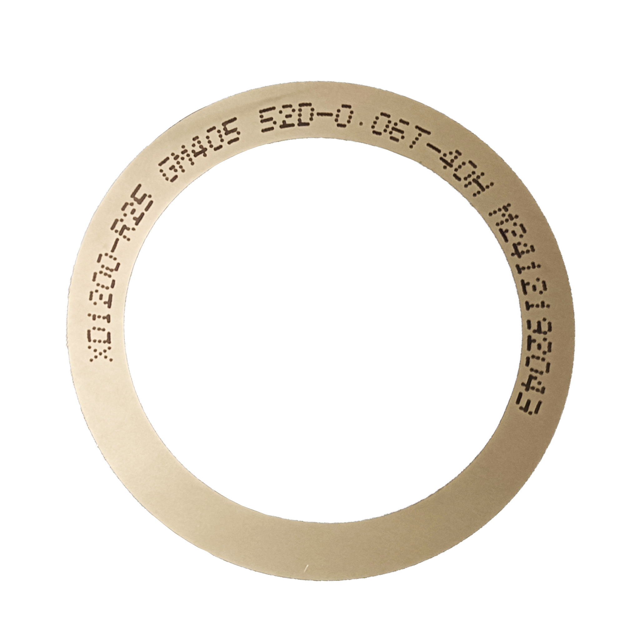
JS Series metal bond Sawing Blade — configured for semiconductor package cutting and dicing.
Why Package Cutting Lines Fail at the Interfaces, Not at the Blade
Cutting lines rarely fail because one component is weak. They fail where components meet. On every wafer, a Sawing Blade touches four neighbours: the spindle of the automatic wafer dicing machine that carries it, the UV tape mounting machine that holds the wafer flat and taut, the wafer cleaning equipment that removes debris afterwards, and the environmental envelope of the cleanroom. Kerf drift, chipping, blade breakage and dimensional scatter are usually the visible symptom of an interface that was never qualified — not a blade that was manufactured incorrectly.
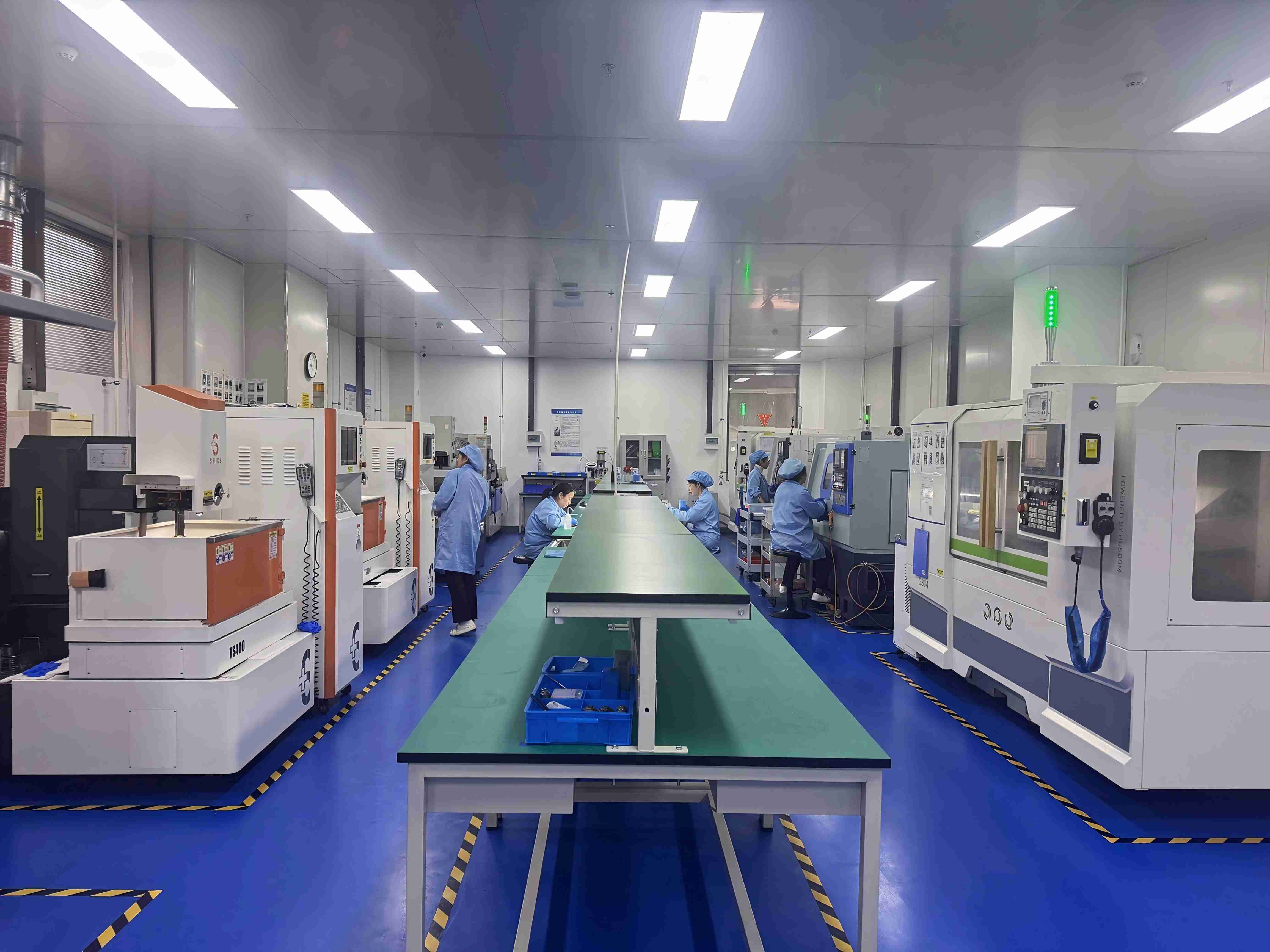
The operating envelope is narrow by design. For semiconductor cutting applications, the working condition is a Class 100/1000 cleanroom with constant temperature of 22±2°C, constant humidity of 45%–55%, dust-free and anti-static conditions, and a high-speed spindle environment. Inside that envelope the blade is expected to deliver high-precision wafer cutting, ultra-thin slicing, narrow kerf, low chipping, high-efficiency cutting and stable dimensional control.
The practical rule: qualify the environment, the tape and the spindle before you qualify the blade. If any of the first three drifts, blade data becomes unreadable and every subsequent purchase decision is guesswork.
Industry Background: A Dicing Market Reshaped by Packaging
Sawing Blade demand tracks the packaging roadmap, not the wafer fab roadmap alone. Market Research Intel values the global wafer dicing blade market at USD 1.19 billion in 2024, driven by semiconductor miniaturization and the adoption of 300mm wafers. Broader diamond saw blade consumption, which includes cutting tools outside semiconductors, was valued at approximately USD 8.60 billion in 2025 and is projected to reach USD 10.16 billion by 2032 according to Maximize Market Research.
Those two figures do not describe the same thing, and buyers should treat any single market number as definition-dependent. For the dicing blade segment alone, published estimates diverge widely — roughly USD 0.437 billion in one source and USD 1.31 billion in another — largely because some analyses count consumables only while others include related equipment scope. Use market data for direction, and use line-level validation for decisions.
Bond chemistry splits demand in a specific way: resin bond blades held a 42% share of the dicing blade market in 2024, while metal bond blades — used for harder materials such as SiC — accounted for 33%. On the application side, optical communication and RF/optoelectronics represented 16% of that market in 2024, reported as USD 69.9 million and attributed to 5G infrastructure expansion. Hubless blades are increasingly dominant for 300mm wafer processing because of superior stability and reduced runout on substrates thinner than 50 µm. Standardization matters too: diamond tools, including sawing blades, are categorized under ISO 22180:2019, which distinguishes CVD diamond-coated types from monocrystalline and polycrystalline types.
Supply is concentrated among a small group of established players. DISCO Corporation, Tokyo Seimitsu (Accretech), Advanced Dicing Technologies (ADT) and Asahi Diamond are identified as leading competitors in the high-precision semiconductor dicing blade market. Sourcing geography is shifting at the same time: China’s exports of cutting blades to Vietnam, India and South Korea grew between 2024 and 2025, with Vietnam up USD 18 million and India up USD 12 million according to OEC data. For line engineers, that means blade comparison now spans more supply regions, not fewer.
Detailed Solution: Integrating a Sawing Blade into the Cutting Line
Integration begins with a blade whose specification is written around machine capability rather than around a catalogue number. WINTIME Semiconductor Technology Co., Ltd. is a manufacturer founded in 2020 that develops, produces and sells high-precision wafer-level cutting blades, cutting tapes and cutting process solutions from a 34,000 m² facility in Rugao, Jiangsu Province, with 35 engineers, two patent technologies and an annual dicing blade capacity of more than 1 million pieces; approximately 30% of output is exported to Southeast Asia, East Asia, North America and Europe. Its Sawing Blade and Dicing Blade programme targets semiconductor manufacturing, semiconductor packaging, optical communication, new functional materials, functional ceramics and alloy materials.
1. A blade specification the line can actually run
Sawing Blade model SB-001 is specified with a thickness range of 8 µm–50 µm, cutting accuracy of ±0.002 mm, spindle speed of 30,000–60,000 rpm, hardness of HRC 65–70, resin or metal bond, and a chip removal rate of ≥1.2 mm³/s. The material set is a resin/metal bond matrix with diamond superabrasive on a high-strength steel base. Each of these numbers maps to a line variable: thickness sets the kerf and the mechanical margin on thin die, accuracy defines street tolerance, the spindle range must sit inside the machine’s rated window, hardness relates to bond wear resistance, and chip removal rate is the ceiling that feed rate and coolant flow must live within.
For ultra-thin work, WINTIME’s completed Ultra-thin Wafer Dicing Blade project reached a thickness below 9 µm in the process, a level described in the company’s project record as achievable in mass production by only a few domestic manufacturers.
2. Automatic wafer dicing machines and spindle matching
The dicing machine contributes the spindle, the feed axes and the recipe; the blade contributes geometry and bond behaviour. Available blade configurations include Diamond, Precision, Semiconductor and Circular Sawing Blades, plus Hubbed, Hubless, Flanged and Serrated types, and the DZY Series Wafer Sawing Blade, DZR Series Sawing Blade and DZR-S Series Slotted Sawing Blade. Hub selection is an integration decision rather than a preference: hubless designs are the trend for 300mm processing on thin substrates, while hubbed and flanged mounting remains relevant where flange stiffness and repeatable mounting are the priority. WINTIME provides technical support for cutting process matching and equipment adaptation, so the blade specification is negotiated against the machine, not delivered as a fixed item.
3. UV tape mounting: the step that decides blade survival
The UV tape mounting machine positions the wafer on UV-curable film inside a frame, and that mounting step sets the mechanical reference for everything that follows. Tape that is slack, unevenly tensioned or contaminated with particles introduces z-height variation under the blade, which shows up as chipping, partial cuts or premature wear. Blade height references are established from the tape surface, and after dicing the film’s adhesion is reduced by UV exposure so die can be picked without mechanical damage. Cutting tapes are part of the same consumable system as the blade, which is why WINTIME supplies both rather than treating the tape as a third-party variable.
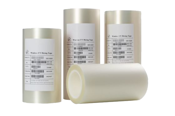
UV film for wafer mounting — the interface between the mounting machine and the Sawing Blade.
4. Wafer cleaning equipment and debris control
Cleaning is not a cosmetic step; it is the verification stage for blade behaviour. A blade that is glazing, loading or wearing unevenly produces more debris and a wider damage zone, and the cleaning module is where that shows up first. The alignment of requirements is deliberate: a blade engineered for high wear resistance, low cutting loss and long service life reduces the debris load the cleaning equipment has to remove, and reduces the risk of residue being carried into downstream package assembly.
5. Constant temperature and humidity: the invisible process parameter
The published working condition for these applications is a Class 100/1000 cleanroom at 22±2°C and 45%–55% relative humidity, dust-free and anti-static. The window is narrow because both the tape system and the blade-to-workpiece interface respond to it: tape modulus and adhesion shift with temperature, static build-up is humidity-dependent, and particles attracted by static charge end up exactly where the blade is cutting. Anti-static behaviour and high dimensional accuracy are therefore listed as special application requirements alongside ultra-thin blade thickness, high wear resistance, low cutting loss, long service life and stable mass production.
6. Blade type plus cut material
Because cutting materials and working conditions differ, WINTIME runs OEM, ODM and customized production, with specifications adapted to the material being cut. Customization covers blade diameter, thickness and spindle hole size; bond type (metal or resin); diamond abrasive grain size and concentration; coating for anti-rust, heat dissipation and wear resistance; cutting performance in terms of speed and service life; export packaging; and non-standard special-shaped blades.
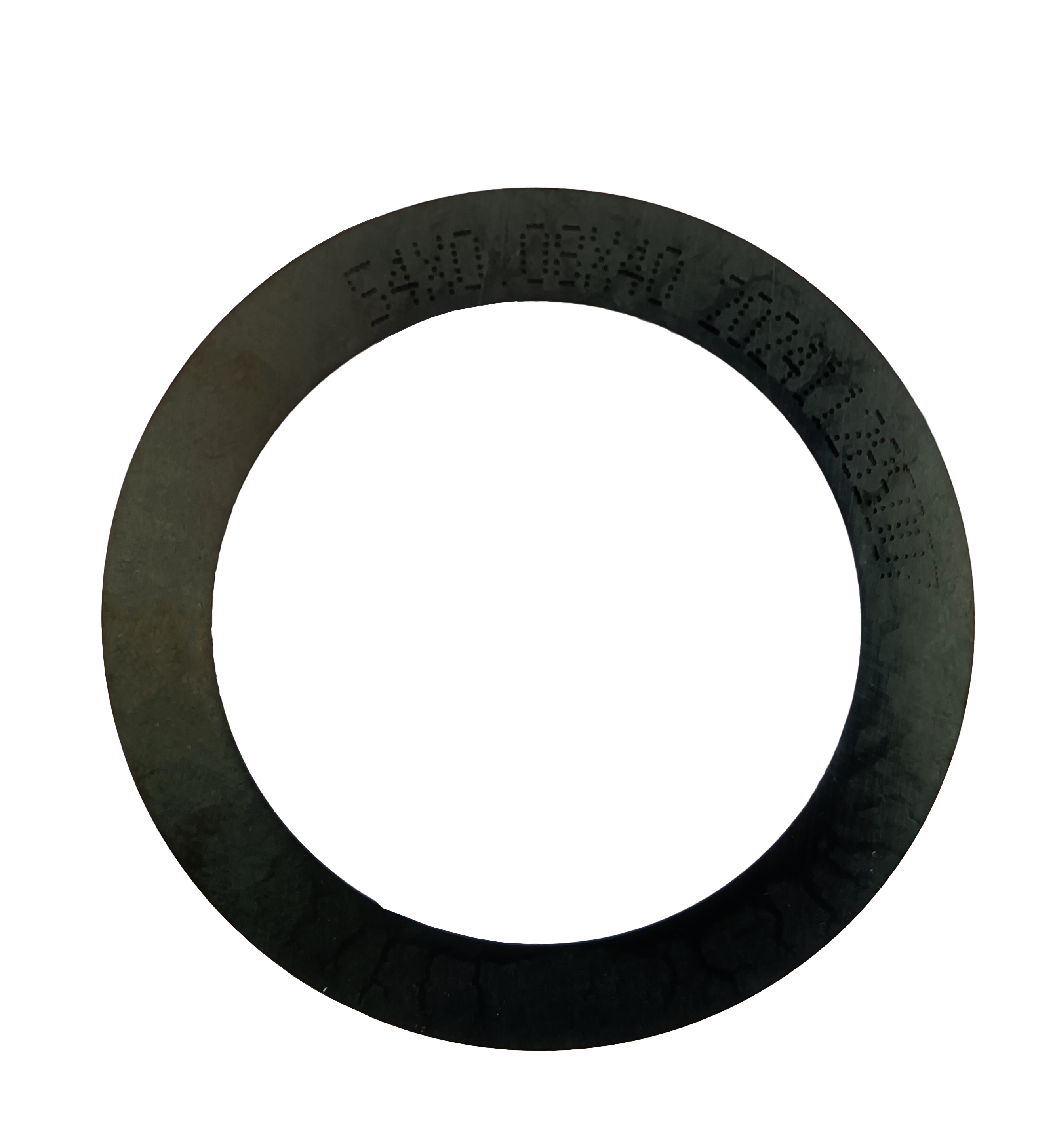
Resin bond Sawing Blade — the bond family that accounted for the larger share of 2024 dicing blade demand.
Step-by-Step: Qualifying a Sawing Blade on a Package Cutting Line
- Define the material stack and the target geometry. Record die thickness, street width, kerf target and the acceptable chipping limit before any blade is quoted. These four numbers are the acceptance criteria for everything that follows.
- Select bond type and blade thickness. Match the bond to the material being cut, then choose thickness inside the 8 µm–50 µm range. Thinner blades buy kerf but demand tighter environmental control.
- Match the blade to the spindle and flange. Confirm that the intended cutting speed sits inside the blade’s 30,000–60,000 rpm window and inside the machine’s rated capability. Dynamic balance is the governing property here.
- Verify mounting and runout. Check blade seating, flange condition and runout before the first cut. WINTIME performs dynamic balance detection with a high-speed dynamic balance tester as a standard control step.
- Lock the tape mounting condition. Confirm tape type, tension and cleanliness on the UV tape mounting machine, then verify wafer flatness in the frame.
- Establish the dicing recipe and confirm chip removal. Set feed rate, spindle speed and coolant so that the blade’s ≥1.2 mm³/s chip removal capacity is not exceeded. Validate with a cutting performance simulation before touching production wafers.
- Clean, inspect and hold the environment. Verify debris removal on the wafer cleaning equipment, inspect kerf and chipping, and log cleanroom class, temperature and humidity. Confirm 22±2°C and 45%–55% RH are held across a full shift, not just at start-up.
WINTIME’s quality control sequence follows the same logic: geometric dimension inspection with vernier caliper and laser diameter gauge, hardness and wear resistance testing on a material testing machine, dynamic balance detection, and cutting performance simulation on the actual material.
Use Cases: Where the Same Line Logic Applies
- Semiconductor packaging lines. Package cutting and dicing where dimensional control and low chipping determine yield in downstream assembly.
- Ultra-thin wafer processing. Applications requiring blade thickness at or below 9 µm, where the blade, tape and environment must be qualified together.
- 300mm wafer processing. Hubless blade configurations are increasingly used at this wafer size for stability and reduced runout on thin substrates.
- Optical communication and RF/optoelectronics. This application group represented 16% of the dicing blade market in 2024, reported as USD 69.9 million, driven by 5G infrastructure expansion.
- Functional ceramics and ceramic substrates. Cutting where kerf and chipping limits are tight and wear resistance drives blade life.
- Precision alloy components. Component separation where dimensional accuracy and repeatability across a production run matter more than raw cutting speed.
Comparison: Bond, Environment and Equipment Parameters
Three tables cover the decisions a package cutting line has to make before a blade purchase becomes repeatable.
| Bond type | 2024 market share (third-party) | Material fit stated by the cited source | What to verify on your line |
|---|---|---|---|
| Resin bond | 42% | Not specified in the cited source; selection depends on cutting material and working condition | Bond hardness, wear rate, feed rate sensitivity |
| Metal bond | 33% | Used for harder materials such as SiC | Spindle load, coolant supply, dressing interval |
| Diamond abrasive | Core functional material in both bond families | Diamond superabrasive on a high-strength steel base | Grain size and concentration versus target kerf |
| Line parameter | Value | Where the value comes from |
|---|---|---|
| Cleanroom class | Class 100/1000 | Published application condition |
| Temperature | 22±2 °C | Published application condition |
| Humidity | 45%–55% RH | Published application condition |
| Blade thickness | 8 µm–50 µm (SB-001); ≤9 µm for ultra-thin applications | Product and application specification |
| Cutting accuracy | ±0.002 mm | Product specification |
| Spindle speed | 30,000–60,000 rpm | Product specification |
| Blade hardness | HRC 65–70 | Product specification |
| Chip removal rate | ≥1.2 mm³/s | Product specification |
| Matched equipment | Function on the cutting line |
|---|---|
| Automatic wafer dicing machine | Carries the high-speed spindle and executes the cutting recipe |
| Semiconductor cutting spindle | Provides the 30,000–60,000 rpm rotation range the blade is specified for |
| UV tape mounting machine | Mounts the wafer on UV film in a frame and sets the flatness reference for dicing |
| Wafer cleaning equipment | Removes cutting debris before downstream packaging steps |
| Wafer testing machine | Verifies die condition after cutting |
FAQ: Sawing Blade Selection for Package Cutting Lines
Which standard applies to diamond Sawing Blades, and what evidence should buyers request?
Diamond tools, including sawing blades, are categorized under ISO 22180:2019, which distinguishes CVD diamond-coated types from monocrystalline and polycrystalline types. Beyond the standard category, buyers should request dimensional inspection records, hardness and wear resistance test records, dynamic balance results, and cutting performance simulation results — the four checks WINTIME performs as part of its quality control.
Can a Sawing Blade be adapted to a specific dicing machine and material stack?
Yes. WINTIME provides OEM, ODM and customized production, and customization covers blade diameter, thickness and spindle hole size; bond type (metal or resin); diamond abrasive grain size and concentration; coating for anti-rust, heat dissipation and wear resistance; cutting speed and service life; export packaging; and non-standard special-shaped blades. Technical support for cutting process matching and equipment adaptation is part of the standard service scope.
What drives cost per wafer — the blade price or something else?
Blade price is usually the smallest line item. Commercial outcomes are driven by kerf-related material loss, blade life, chipping and rework, and machine downtime. WINTIME’s minimum order quantity is 50 pieces for standard products and 300 pieces for customized products, with flexibility for long-term cooperative customers, which allows cost to be assessed per wafer rather than per piece.
How can a packaging line validate a blade before committing to volume?
Run a controlled trial on production material rather than a laboratory coupon. The 50-piece standard minimum order supports exactly that kind of line trial, and WINTIME also provides product application training for new customers and customized after-sales service for bulk procurement customers. Lines that want to start with a validation sample or quotation can reach the team through the contact details at the end of this guide.
What lead time and supply continuity should be planned for?
WINTIME quotes 2–5 working days for standard products and 10–25 working days for customized orders, adjustable for large orders, backed by an annual dicing blade capacity of more than 1 million pieces together with long-term supply guarantees and inventory support. Quality issues are investigated and resolved within 48 hours. Requests can be sent to shenxiangfei@ntwintime.com or by WhatsApp at +86 18888053207.
Conclusion: Lock the Line, Then Lock the Blade
A Sawing Blade is the last variable in a package cutting line, not the first. The line’s environment (Class 100/1000, 22±2°C, 45%–55% RH, anti-static), the UV tape mounting step, the spindle’s speed window and the cleaning module all shape what the blade can do. When those four are controlled, blade data becomes meaningful: thickness between 8 µm and 50 µm, cutting accuracy of ±0.002 mm, hardness of HRC 65–70 and a chip removal rate of ≥1.2 mm³/s can be translated directly into kerf, chipping and yield outcomes.
WINTIME Semiconductor Technology Co., Ltd. supports that qualification process from Rugao, Jiangsu Province, with cutting tapes, cutting process support and an application engineering team of 35 engineers.
WINTIME application engineering and commercial support, Rugao, Jiangsu Province.
Next Step: Sample, Quote or Catalogue
Send your material stack, dicing machine model and target kerf, and WINTIME will return a blade configuration, trial quantity and lead time. The full product catalogue is available for download.
Download the WINTIME Sawing Blade Catalogue
Email: shenxiangfei@ntwintime.com | Tel / WhatsApp: +86 18888053207 | en.wintime.net.cn
Address: No. 868, Fushou East Road, Rugao City, Jiangsu Province.
Have Questions or Need More Details?
Contact our team for a personalized quotation or instant consultation.
Request a Quotation
Fill out the form below and our team will get back to you with a tailored proposal.
WhatsApp Direct Chat
Prefer to chat in real-time? Message us on WhatsApp for instant assistance & quick answers.
- Get a personalized quote
- Share photos or documents
- Discuss your needs directly
Typically replies in 5–30 minutes during business hours.