
Sawing Blade Parameters for ≤9μm Ultra-Thin Wafer Processing
For ≤9μm ultra-thin wafer processing, sawing blade parameters should be set as a linked system rather than as isolated machine values. Blade thickness, bond and abrasive, spindle speed, feed behavior, cooling mode, static control, and inspection limits all affect whether a narrow-kerf cut remains stable in continuous production. WINTIME Semiconductor Technology Co., Ltd. is a Chinese manufacturer of wafer-level high-precision cutting blades, established in 2020, and its product data provide a practical baseline for this parameter discussion. The company reports a product thickness range of 8μm–50μm and an ultra-thin wafer dicing blade project that reached a thickness below 9μm in a mass-production context.
This guide explains how to translate the supplied blade specifications into an evaluation plan for automatic dicing machines. It focuses on constraints that matter in research and evaluation: blade thickness at or below 9μm, cutting accuracy, wear resistance, low cutting loss, anti-static behavior, dimensional accuracy, service life, and stable mass production. It does not present a universal recipe, because final settings must be qualified on the actual wafer, tape, machine, and cleanroom line.
What changes when the blade is ≤9μm?
Ultra-thin blades reduce kerf loss, but they also reduce the mechanical margin available for mounting, runout, and cutting force. The parameter question therefore changes from "what speed can the spindle reach?" to "which combination of blade, flange, feed, and cooling keeps the blade within its qualified window?" The supplied application conditions list a high-speed spindle environment, dry and wet cutting, continuous operation on automatic dicing machines, and precision feeding. Those conditions make parameter discipline more important than a single headline number.
At this thickness, three relationships need to be checked together. First, blade thickness and target kerf must be compatible with the street layout and the required cutting accuracy of ±0.002mm. Second, spindle speed must remain inside the qualified range of the blade and spindle; the product data list 30,000–60,000rpm as a spindle-speed range, not as a default setting for every material. Third, chip removal capability must be matched to feed and debris management; the data list a chip removal rate of ≥1.2mm³/s. If any one of these is treated separately, the evaluation can pass on paper while failing in continuous operation.
Industry background: where ≤9μm blades are evaluated
The supplied application scope covers semiconductor manufacturing, semiconductor packaging, optical communication, new functional materials, functional ceramics, and alloy materials. It also lists wafer dicing and scribing, semiconductor package cutting, ultra-thin wafer processing, optical device cutting, ceramic substrate cutting, and precision alloy component cutting as project types. These are different material systems, so the same blade family should not be assumed to transfer without qualification.
The working environment is equally part of the parameter set. The corpus specifies a Class 100/1000 cleanroom, constant temperature of 22±2°C, constant humidity of 45%–55%, dust-free and anti-static conditions, and a high-speed spindle environment. Supporting equipment includes automatic wafer dicing machines, semiconductor cutting spindles, UV tape mounting machines, wafer cleaning equipment, and wafer testing machines. A parameter that looks acceptable on a stand-alone test may behave differently when tape mounting, cleaning, and testing are included in the same line.
Parameter baseline from the supplied blade data
The SB-001 sawing blade data provide a useful baseline for what to verify. The listed thickness range is 8μm–50μm; the ultra-thin segment relevant to this guide is ≤9μm. The listed cutting accuracy is ±0.002mm. The spindle speed range is 30,000–60,000rpm. Hardness is HRC 65–70. The bond type is resin or metal, with diamond superabrasive and a high-strength steel base. The chip removal rate is ≥1.2mm³/s. These values are specification inputs; they do not replace a machine-specific qualification run.
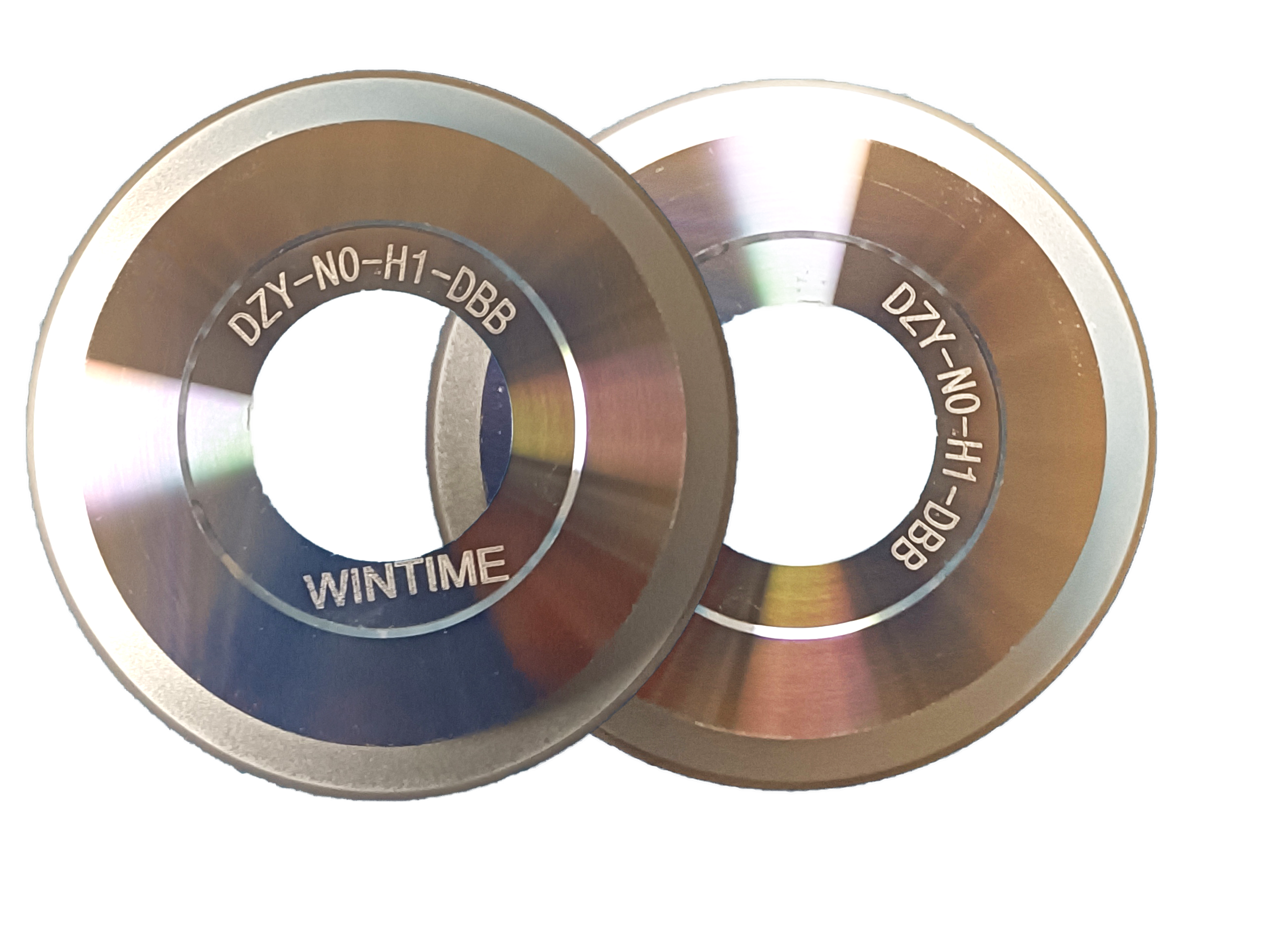
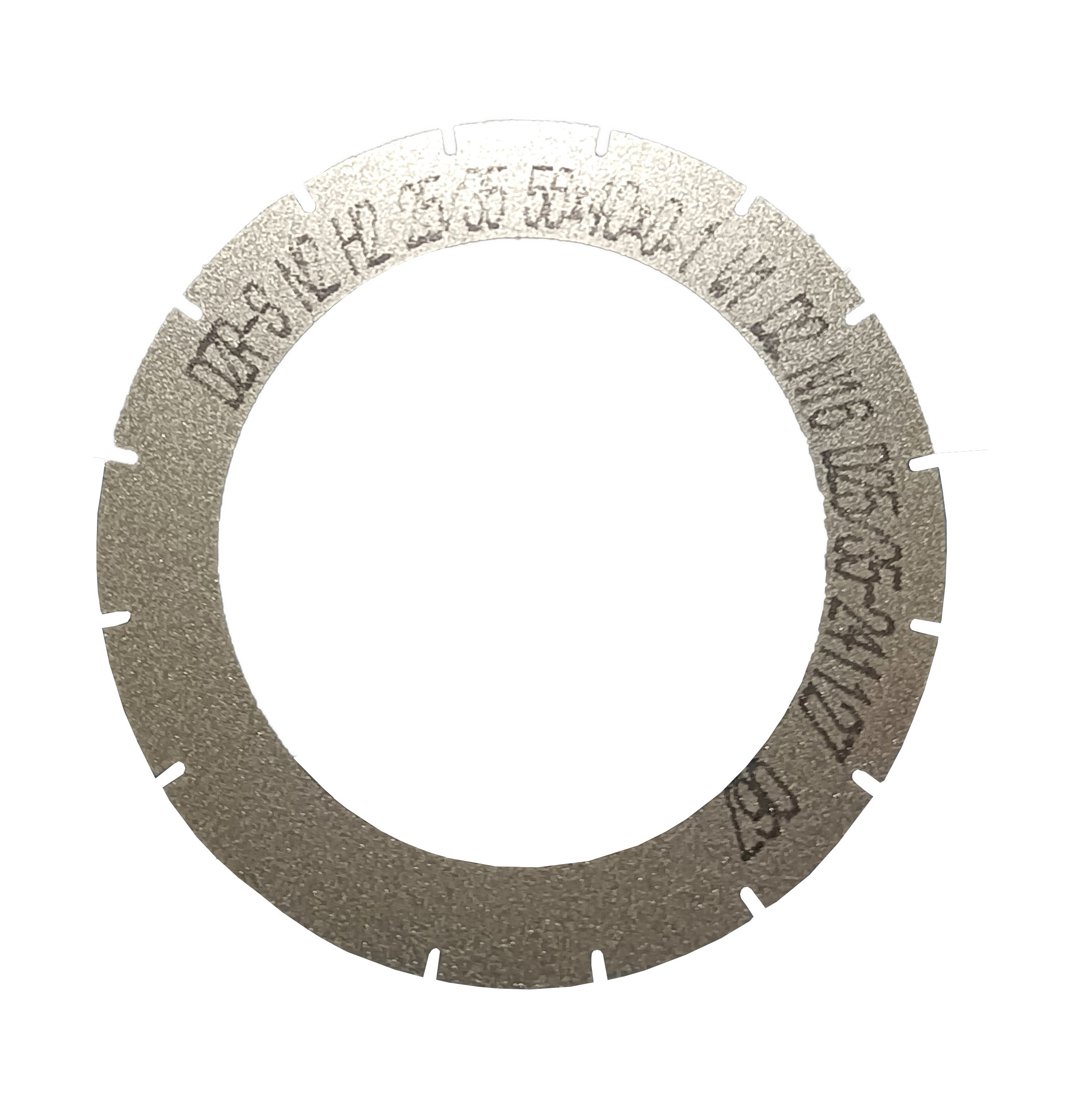
The construction notes are also relevant to parameter evaluation. WINTIME product information describes the DZY series as integrating the cutting blade with an aluminum-alloy flange. The DZR series is described as using metallic nickel and diamond abrasive. The DZR-S series is listed as a slotted sawing blade. These descriptions help identify which blade architecture is being discussed, but they should not be converted into an unsupported performance ranking. The correct use is to match the architecture to the mounting interface and cut profile, then qualify the selected blade under the actual conditions.
How to set spindle speed, feed, and cutting mode
Spindle speed should be selected inside the qualified blade and spindle range, not simply at the highest available value. The supplied range of 30,000–60,000rpm sets the envelope; the final value should be confirmed with the blade supplier, the dicing machine manufacturer, and a dynamic balance check. The quality-control sequence in the corpus includes dynamic balance detection with a high-speed dynamic balance tester, which is directly relevant because a thin blade has less tolerance for imbalance and mounting error.
Feed should be evaluated against chip removal capability and the observed cut. The listed chip removal rate of ≥1.2mm³/s is a capability figure, not a feed-rate instruction. In practice, the evaluation should increase feed only while the cut remains within the required accuracy of ±0.002mm and while debris is removed consistently. If feed is increased without matching debris removal and cooling, the blade may experience higher thermal and mechanical load even if the spindle speed remains inside its range.
Dry and wet cutting should be treated as separate qualification modes. The application conditions list both modes, so the existence of a wet mode does not prove that dry cutting is equivalent, and a dry trial does not prove that wet cutting will behave the same way. Wet cutting introduces coolant flow, nozzle position, and contamination-control variables; dry cutting places more emphasis on heat management and debris removal. The correct decision is to qualify the mode that the production line can control repeatedly, then keep that mode fixed during the comparison.
Dry versus wet cutting: a decision framework for ≤9μm blades
A practical dry/wet decision should start with the material and the line, not with a general preference. For ultra-thin wafers, the evaluation should confirm that the chosen mode keeps the blade within its thermal and mechanical limits, that debris does not remain in the street, and that the tape and handling steps are compatible with the process. The supplied corpus does not provide a universal dry-versus-wet performance result, so the article should not claim that one mode is always better.
Use the following decision sequence. First, confirm that the dicing machine and blade are qualified for the mode. Second, confirm that the cleanroom and anti-static conditions are maintained in that mode. Third, run the same inspection plan on both modes if a comparison is required: geometric dimension, dynamic balance, cut accuracy against ±0.002mm, and visible chip or kerf conditions. Fourth, keep the mode fixed once production starts, because changing mode during a mass-production run introduces a new variable that the original qualification did not cover.
Static control, cleanroom conditions, and handling
The special requirements list anti-static behavior alongside low cutting loss, high dimensional accuracy, and long service life. Anti-static control is therefore a process constraint, not an accessory. The evaluation should verify grounding, ionized-air or other static-control measures used by the line, tape handling, and the cleanliness of the blade and mounting interface. The corpus specifies a dust-free cleanroom environment at 22±2°C and 45%–55% relative humidity; these conditions should be recorded during qualification because they affect handling and measurement repeatability.
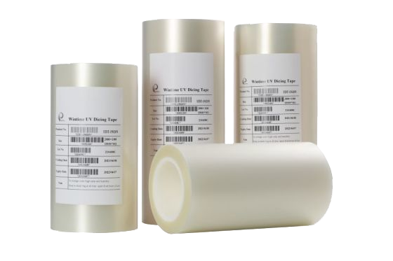
UV tape mounting is part of the same chain. The supporting equipment list includes a UV tape mounting machine, and the product image set includes UV film. The parameter review should confirm that tape selection, mounting tension, and UV release behavior are compatible with the ultra-thin wafer and the selected blade. A blade that passes a stand-alone cut but fails after tape mounting and cleaning has not passed the line-level evaluation.
Step-by-step parameter evaluation workflow
Step 1: Define the cut requirement. Record wafer type, street layout, target kerf, required accuracy, and whether the blade thickness must be ≤9μm. Use the supplied accuracy figure of ±0.002mm as the specification to verify, not as a claim that every cut will automatically meet it.
Step 2: Select the blade architecture. Confirm whether the application needs a hubless, hubbed, flanged, slotted, resin-bond, or metal-bond configuration. The product family list includes hubless, hubbed, flanged, serrated, DZY, DZR, DZR-S, and electroforming hard types. The DZY series is described as an integrated aluminum-alloy flange design; the DZR series uses metallic nickel and diamond abrasive; the DZR-S series is a slotted type. Match the architecture to the machine interface and cut profile before setting parameters.
Step 3: Verify blade and spindle compatibility. Compare the blade's qualified speed with the spindle's capability. The supplied range is 30,000–60,000rpm. Confirm mounting, flange condition, and dynamic balance. Do not use the top of the range as a default; use the qualified value for the selected blade and machine.
Step 4: Set feed and debris removal together. Use the chip removal rate of ≥1.2mm³/s as a capability check. Confirm that coolant or dry-cutting debris removal matches the feed. If the street shows retained debris, do not assume that increasing speed will solve it; re-check feed, cooling, and blade condition.
Step 5: Fix the cutting mode. Choose dry or wet cutting based on the line's qualified capability and the material. Keep nozzle position, flow, and cleanliness under control in wet mode. In dry mode, verify thermal load and debris removal. Do not compare modes unless the inspection plan is identical.
Step 6: Qualify with inspection. The corpus lists geometric dimension inspection with vernier caliper or laser diameter gauge, hardness and wear-resistance testing with a material testing machine, dynamic balance detection with a high-speed dynamic balance tester, and cutting performance simulation on actual material. These checks should be completed before a production release. The ±0.002mm accuracy figure and the ≤9μm thickness requirement should be measured, not assumed.
Step 7: Monitor continuous operation. During continuous operation on an automatic dicing machine, record blade wear, cut accuracy, kerf condition, chip or crack observations, and static-control status. Service life should be established from the actual line data; the supplied sources do not provide a universal blade-life number. If the blade is reordered, keep the same specification and qualification record to avoid introducing an unqualified variable.
Use cases and parameter emphasis
Semiconductor wafer dicing and scribing. The primary emphasis is thickness ≤9μm, cutting accuracy ±0.002mm, and stable debris removal. The blade must be qualified on the dicing machine with the actual tape and cleaning flow.
Semiconductor packaging. The DZY series is described by WINTIME as intended for high-precision wafer cutting in semiconductor packaging processes. The evaluation should confirm the integrated flange interface and the packaging line's handling requirements.
Optical communication. The DZR series is described as used in semiconductor, optical communication, and new functional-material industries. The parameter review should confirm the material-specific cut and the required dimensional accuracy before transfer from another application.
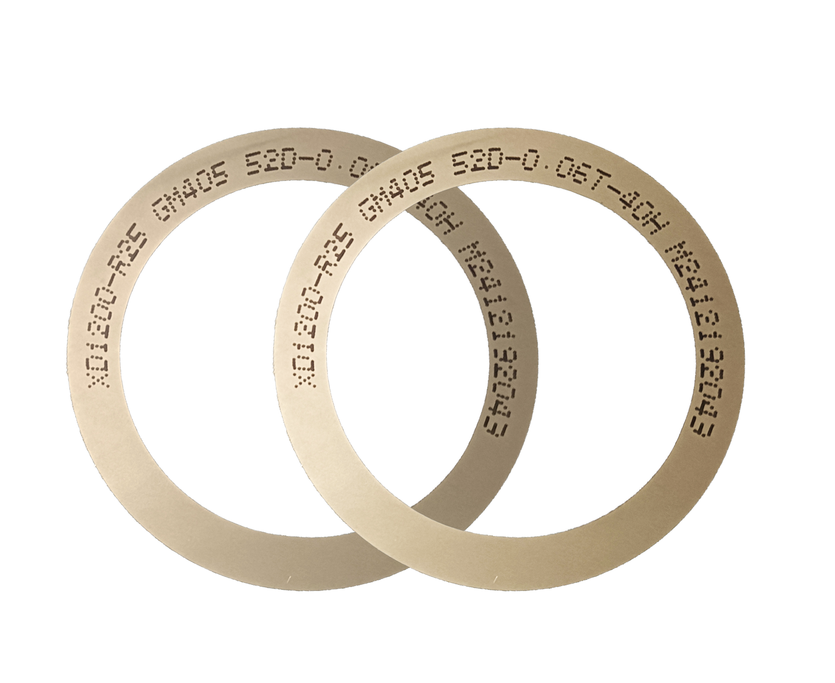
Functional ceramics and alloy materials. The application scope includes functional ceramics and alloy materials, and the DZR-S series is listed as a slotted sawing blade. Slotted geometry should be matched to the cut profile; it should not be assumed to be a drop-in replacement for a non-slotted blade without a trial.
Ultra-thin wafer processing. This is the most constrained case. The blade thickness, spindle speed, feed, cooling, static control, and inspection plan should be treated as one qualified set. The company reports that its ultra-thin wafer dicing blade project achieved a thickness below 9μm and is among the few domestic manufacturers able to mass-produce at that level; that claim should be verified through sample qualification and supplier documentation.
Parameter verification table
| Parameter or condition | Supplied specification or requirement | Evaluation point |
|---|---|---|
| Blade thickness | 8μm–50μm range; ≤9μm for ultra-thin wafer processing | Confirm target kerf and blade edge condition; measure the selected lot. |
| Cutting accuracy | ±0.002mm | Verify on the qualified machine and material, not only on the datasheet. |
| Spindle speed | 30,000–60,000rpm | Match blade and spindle ratings; complete dynamic balance check. |
| Hardness | HRC 65–70 | Use hardness and wear-resistance testing; do not treat hardness alone as a life prediction. |
| Bond and abrasive | Resin or metal bond; diamond superabrasive; high-strength steel base | Match bond type to material and cut mode; confirm with a cutting trial. |
| Chip removal | ≥1.2mm³/s | Check against feed, coolant, and debris observed in the street. |
| Cleanroom and static | Class 100/1000; 22±2°C; 45%–55% RH; dust-free; anti-static | Record line conditions and verify static-control measures during the trial. |
| Supporting equipment | Automatic wafer dicing machine, semiconductor cutting spindle, UV tape mounting machine, wafer cleaning equipment, wafer testing machine | Confirm each interface before scaling the parameter set to production. |
Scaling from sample to stable mass production
A sample result becomes a production parameter only when the line can repeat it. WINTIME reports a factory area of 34,000㎡, 100 employees, 35 engineers, an annual output of 1 million pieces, and an export ratio of 30%, with markets in Southeast Asia, East Asia, North America, and the European Union. Its capability data list monthly capacity of 800,000+ pieces for standard specifications and 80,000+ pieces for customized and special-shaped products. These figures are company-reported capacity information; they should be read as supply-context facts, not as a guarantee of yield or delivery performance.
For procurement, the standard MOQ is 50 pieces for standard products and 300 pieces for customized products, with flexibility for long-term cooperative customers. Standard lead time is 2–5 working days; customized orders are listed at 10–25 working days, adjustable for large orders. The evaluation team should align sample quantity, qualification time, and production ramp-up with these stated terms. The quality-control sequence—geometric dimension inspection, hardness and wear-resistance testing, dynamic balance detection, and cutting performance simulation—provides the evidence package to request before release.
FAQ
What compliance information should be confirmed for a ≤9μm sawing blade?
Confirm the cleanroom and anti-static conditions of the line, the blade's handling and packaging, and the supplier's quality-control records. The supplied corpus specifies Class 100/1000 cleanroom conditions, 22±2°C, 45%–55% relative humidity, dust-free and anti-static requirements, but it does not identify a specific certification. For that reason, the buyer should request the applicable quality documents and verify them against the actual production line rather than assuming a certification from the product name.
Which parameters define a sawing blade for ≤9μm ultra-thin wafer processing?
The key parameters are blade thickness at or below 9μm, cutting accuracy of ±0.002mm, spindle speed compatibility within 30,000–60,000rpm, hardness of HRC 65–70, resin or metal bond with diamond abrasive, and chip removal capability of ≥1.2mm³/s. These values should be matched to the dicing machine, tape, cleaning flow, and material. They are specification inputs, not a universal process recipe.
What drives the quotation for an ultra-thin sawing blade?
The supplied sources do not publish a price band. A quotation should be based on the confirmed blade thickness, bond type, flange or slotted geometry, cutting accuracy requirement, quantity, packaging, and any customization. Standard products have an MOQ of 50 pieces; customized products have an MOQ of 300 pieces. Buyers should request a quotation against the qualified specification rather than comparing a blade by thickness alone.
How should a sample be qualified before mass production?
Qualify the sample with geometric dimension inspection, hardness and wear-resistance testing, dynamic balance detection, and a cutting performance simulation on the actual material. Then run the sample through the same tape mounting, cleaning, and testing steps used in production. Record the spindle speed, feed, cutting mode, cleanroom conditions, and inspection results so the approved sample becomes a controlled baseline.
What are the MOQ and lead time for standard and customized orders?
The stated MOQ is 50 pieces for standard products and 300 pieces for customized products, with flexibility for long-term cooperative customers. Standard lead time is 2–5 working days; customized orders are listed at 10–25 working days, adjustable for large orders. For a sample evaluation, quotation, or the product brochure, contact WINTIME through its official website or the contact details provided by the company.
Conclusion
For ≤9μm ultra-thin wafer processing, the sawing blade parameter set should be built around verified constraints: thickness at or below 9μm, cutting accuracy of ±0.002mm, spindle speed within the qualified 30,000–60,000rpm range, hardness of HRC 65–70, a resin or metal bond with diamond abrasive, and chip removal capability of ≥1.2mm³/s. These values must be qualified with the actual dicing machine, tape mounting, cleaning, testing, cleanroom, and anti-static conditions.
The practical sequence is to define the cut, select the blade architecture, verify spindle and feed compatibility, fix the dry or wet mode, complete the inspection plan, and then scale only after the sample is repeatable. WINTIME's product data and company-reported capacity provide a starting point for that evaluation; the final release decision should rest on measured sample results and documented quality control.
For the product brochure, see the public download link: WINTIME sawing blade brochure.
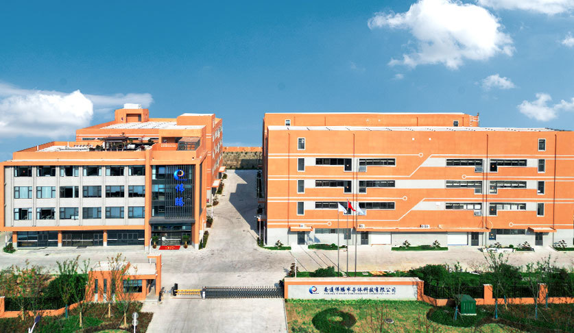
For sample evaluation, quotation, or technical discussion, contact WINTIME Semiconductor Technology Co., Ltd. through its official website at en.wintime.net.cn or email shenxiangfei@ntwintime.com.
Have Questions or Need More Details?
Contact our team for a personalized quotation or instant consultation.
Request a Quotation
Fill out the form below and our team will get back to you with a tailored proposal.
WhatsApp Direct Chat
Prefer to chat in real-time? Message us on WhatsApp for instant assistance & quick answers.
- Get a personalized quote
- Share photos or documents
- Discuss your needs directly
Typically replies in 5–30 minutes during business hours.