
Sawing Blade vs. Laser Cutting for Ceramic Substrates: Which Process Wins on Kerf and Chipping?
Kerf width and edge chipping decide how many good ceramic parts a cutting process delivers. This head-to-head guide compares a diamond sawing blade with laser cutting on both measurements, then adds the criteria that usually settle the decision: dimensional control, compatibility with precision feeding operations, cleanroom constraints, and whether the winning process can be supplied consistently at production volume.
Two numbers carry most of the economics in ceramic substrate cutting. Kerf width determines how many parts fit into a sheet or wafer, and edge chipping determines how many of those parts survive inspection. Spindle speed, blade price and machine footprint all matter, but they matter second.
The short answer: where the substrate is thin and brittle, where part count depends on every micrometre of kerf, and where the cut must repeat across high volumes, a diamond sawing blade on a controlled dicing platform is generally the more predictable route for kerf and chipping. Laser cutting generally becomes the stronger option when the process must be non-contact, when outlines are complex or change frequently, or when the workpiece and the downstream steps tolerate heat input. There is no universal winner — and a comparison that skips workpiece analysis is not answering the question.
Problem Definition: Why Kerf and Chipping Are Hard to Compare Fairly
Kerf width is not one fixed value. In mechanical sawing it results from blade thickness together with the wear of the bond and diamond grit during the cut, so it can drift across blade life. In laser cutting it results from the focused beam and how strongly the workpiece absorbs that energy, so it responds to material composition and thickness. Comparing a blade's nominal thickness with a laser's focused spot compares two different quantities.
Chipping has the same problem. Top-edge chipping, backside chipping and subsurface micro-cracks are different defects with different mechanisms, and they are measured with different methods. Two routes can both be described as "low chipping" while referring to different surfaces with different acceptance limits, which is why written criteria beat adjectives in any quotation.
The third difficulty is process lock-in. The cutting method determines the platform, the fixture or tape strategy, the coolant or exhaust handling, the operator routine and the consumable supply chain. Changing route after qualification normally means requalifying the line, so this is not a decision that can be deferred.
Reformulated, the useful question is narrower: on this specific ceramic workpiece, in this cleanroom, at this expected annual volume, which process meets the kerf budget and the chipping criteria and can still be supplied year after year?
Industry Background: What Is Changing Around Ceramic Substrate Cutting
The consumable tool market is expanding, which matters because it indicates where blade capacity is going. Maximize Market Research valued the global diamond saw blade market at approximately USD 8.60 billion in 2025 and projects it to reach USD 10.16 billion by 2032. Inside the semiconductor segment, Market Research Intel valued the wafer dicing blade market at USD 1.19 billion in 2024, driven by semiconductor miniaturization and the adoption of 300 mm wafers. Published figures for that segment vary with scope — the same research house has been reported at USD 1.31 billion, while Dicing Blade Market Insights reported USD 0.437 billion — so any single number should be read as a scoping choice rather than a precise market truth.
Two technology trends affect ceramic and wafer cutting decisions directly. Hubless dicing blades are increasingly dominant for 300 mm wafer processing because they provide superior stability and reduced runout on thinner substrates below 50 µm; reduced runout converts into tighter kerf control and lower edge chipping, which is why geometry belongs in the specification. Bond mix matters for the same reason: resin bond blades held a 42% share of the dicing blade market in 2024, while metal bond blades — used for harder materials such as SiC — accounted for 33%.
Demand mix is shifting as well. Optical communication and RF/optoelectronics applications accounted for 16% of dicing blade market share in 2024, a value of USD 69.9 million, driven by 5G infrastructure expansion — a category where small, brittle parts make edge quality critical. Supply is shifting too: OEC data shows China's exports of cutting blades growing significantly between 2024 and 2025, with Vietnam up by USD 18 million and India up by USD 12 million, which reflects how normal it has become to source precision blades from Asian manufacturers. For specification language, diamond tools including sawing blades fall under ISO 22180:2019, which distinguishes CVD diamond-coated types from monocrystalline and polycrystalline types.
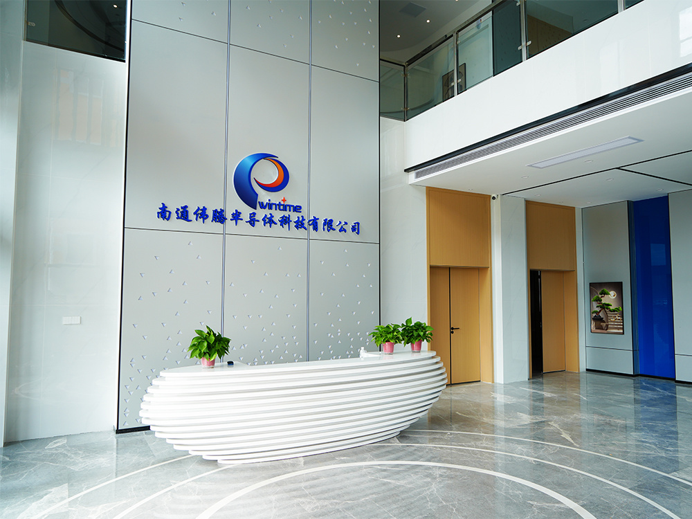
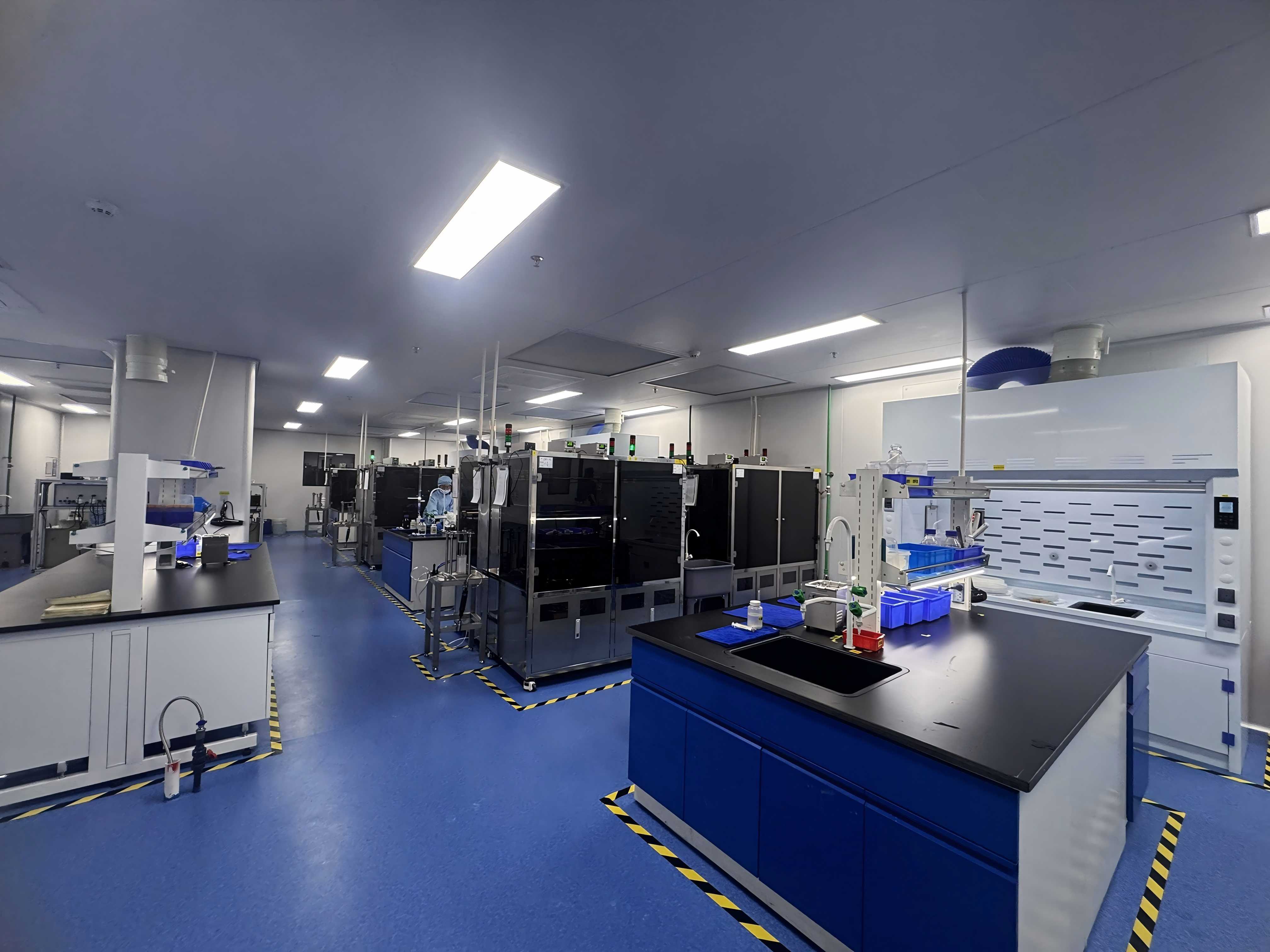
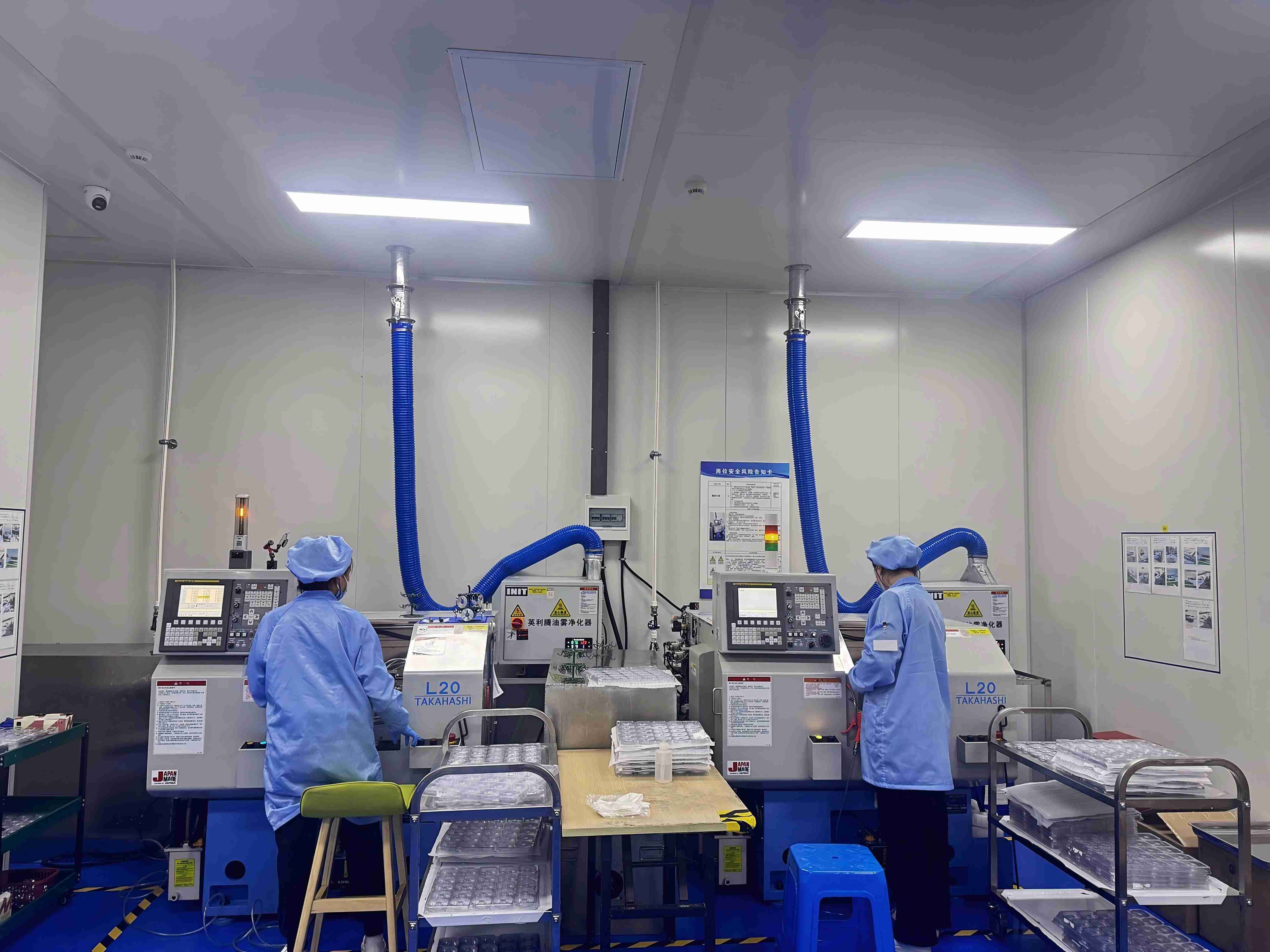
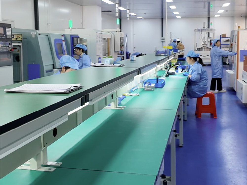
Established suppliers in this field, as listed by Credence Research, include DISCO Corporation, Tokyo Seimitsu (Accretech), Advanced Dicing Technologies (ADT) and Asahi Diamond. WINTIME Semiconductor Technology Co., Ltd. is a newer entrant: founded in 2020, the company develops, produces and sells high-precision wafer-level cutting blades and cutting solutions from a 34,000 m² facility, with 100 employees including 35 R&D engineers, two patent technologies, and annual output of more than one million dicing blades following its 2023 Nantong WINTIME Semiconductor Special Materials project. Around 30% of output is exported to markets in Southeast Asia, East Asia, North America and Europe. The company's ultra-thin wafer dicing blade project reached a blade thickness below 9 microns and is in mass production.
Detailed Solution: How the Sawing-Blade Route Is Engineered for Ceramic Substrates
When the decision falls to mechanical cutting, the process is not a single blade on a single machine. It is a small system: blade construction matched to the workpiece, geometry matched to the feeding platform, and a supply plan matched to production volume.
Blade construction: bond type follows workpiece hardness
A diamond sawing blade removes material with diamond grit held in a bond matrix. The bond controls how grit is retained and released as it wears, so bond selection follows workpiece hardness and the required surface finish. Market data reflects that split: resin bond blades held a 42% share of the 2024 dicing blade market, while metal bond blades — used for harder materials such as SiC — accounted for 33%. For ceramic substrate programs, the practical implication is that bond family belongs in the technical specification, because it determines how kerf behaves over blade life rather than only at the first cut.
Geometry: hubless blades and runout control
Blade geometry is the second lever, and it is the one most closely tied to chipping. Hubless dicing blades are increasingly dominant for 300 mm wafer processing because they provide superior stability and reduced runout on substrates below 50 µm. Lower runout means the cutting edge tracks a tighter plane, which reduces the variation that appears as uneven kerf and edge chipping. WINTIME's catalog covers diamond sawing blades, hubless sawing blades and named series including the DZY Series wafer sawing blade, the DZR Series sawing blade, the DZR-S Series slotted sawing blade and electroforming hard sawing blades, with application families spanning semiconductor wafer sawing, optical communication sawing, functional ceramic sawing and alloy material sawing.
Process support: what a blade needs around it
No blade holds kerf and chipping targets alone. Platform accuracy, blade exposure, feed control, workpiece support and coolant delivery all contribute to the result, and filtration decides whether swarf is carried away or re-enters the cut. This is also where the two routes diverge operationally: mechanical sawing manages solid debris through fluid handling and filtration, while a thermal process manages heat and fume. Both can run in cleanroom environments, but they require different support systems — so the cleanroom requirement should be written against the process, not against the machine alone.
Supply capability: the part of the decision that lasts
Blades are consumables, so supply capability is part of the technical answer rather than a commercial afterthought. WINTIME's monthly production capacity is over 800,000 pieces for standard specifications and over 80,000 pieces for customized and special-shaped products, which matters when one program needs both volume parts and special geometries.
- Quality management: an ISO 9001 quality management system, standard operating procedures, dedicated quality inspectors tracking each production batch, and batch quality files that allow traceability and recall if a batch problem appears.
- Batch consistency: standardized process parameters, automated production equipment to reduce manual error, a batch production data tracking system, and comparative testing between adjacent batches.
- Acceptance and commercial terms: pre-shipment testing and third-party inspection (SGS) as acceptance criteria; MOQ of 100 pieces for standard models and 500 pieces for customized models, with flexible MOQ for trial orders below 500 pieces at a slight price adjustment based on customization complexity; FOB/CIF delivery terms; 30/70 payment terms.
Step-by-Step Breakdown: Nine Steps From Workpiece to Qualified Process
Use this sequence to convert the kerf-versus-laser question into a documented decision that survives an audit.
- Characterize the workpiece. Record material type, thickness, metallization or coating, part geometry and the dimensional tolerance that actually matters downstream. Kerf and chipping limits cannot be set before this step.
- Set the kerf budget. Derive kerf from the required number of parts per sheet or wafer, then check whether the available blade thickness range or the thermal cutting width can meet it with margin for wear or variation.
- Define chipping acceptance criteria in writing. Specify which surfaces are inspected, which defect sizes are rejected, and which measurement method applies. This is the most common source of dispute between process routes.
- Assess thermal sensitivity. If the workpiece or its metallization cannot tolerate localized heat input, the thermal route becomes hard to defend and mechanical cutting becomes the default. If heat input is acceptable, laser becomes a genuine option rather than a fallback.
- Match the feeding platform. Confirm spindle and feed capability, blade exposure control and how the workpiece is held — tape, carrier or fixture. Mechanical cutting lives or dies on stable feeding, which is where hubless geometry and runout control earn their place.
- Confirm cleanroom handling. Decide how debris is managed — fluid and filtration for sawing, exhaust and fume handling for a thermal process — and write the requirement against the process so facility qualification covers it.
- Build the cost model on good parts. Compare cost per accepted part rather than cost per cut: kerf economy, blade life, validation effort and the scrap created by chipping belong in the same model.
- Validate on a trial lot. Run the candidate process on real material with pre-shipment testing and, where required, third-party inspection (SGS), and compare performance across adjacent batches to confirm consistency.
- Lock the supply plan. Confirm monthly capacity for standard and custom specifications, MOQ rules, delivery and payment terms, and batch traceability before the process moves into volume production.
Use Cases: Where Each Route Belongs
Functional ceramic substrates
Thin, brittle functional ceramics cut at a high part count per sheet are the classic case where kerf economy and chipping control dominate. Every micrometre of kerf reduces part count, and every chipped edge becomes scrap, so a matched bond with controlled runout is generally easier to defend than a process whose cut width shifts with material absorption.
Semiconductor wafer dicing
Wafer programs push both requirements at once. Substrates below 50 µm are the reason hubless blades are increasingly dominant for 300 mm processing, and ultra-thin capability matters at the extreme end — WINTIME's ultra-thin wafer dicing blade project reached a blade thickness below 9 microns and is in mass production.
Optical communication devices
Optical communication and RF/optoelectronics accounted for 16% of dicing blade market share in 2024, valued at USD 69.9 million and driven by 5G infrastructure expansion. Parts in this category are small and brittle, so edge quality carries as much weight as throughput.
Alloy and harder-material workpieces
Harder workpiece families change the bond decision rather than the process logic: metal bond blades are used for harder materials such as SiC, which is why bond selection is specified per workpiece instead of per machine.
Where laser cutting holds its ground
Laser cutting remains attractive when the process must be non-contact, when outlines are complex or change frequently, when volumes are too low to justify tooling, or when the workpiece and downstream steps tolerate heat input. Those are legitimate advantages, and they are why the ceramic cutting market supports both routes rather than one.
Comparison Table: Sawing Blade vs. Laser Cutting on Eight Decision Criteria
Read the table as a checklist of questions to settle on your own workpiece, not as a specification sheet for either process.
| Criterion | Diamond sawing blade (mechanical) | Laser cutting (thermal) |
|---|---|---|
| Kerf width and repeatability | Set primarily by blade thickness plus bond and grit wear; planned from the blade specification and monitored through blade life. | Set by the focused beam and how strongly the material absorbs that energy; sensitivity to thickness and composition. |
| Edge chipping and micro-cracks | Mechanical removal; chipping managed through bond and grit choice, blade exposure, feed control and runout. | Thermal removal; edge and subsurface effects associated with heat input are the main quality consideration. |
| Heat input to the workpiece | Coolant-managed mechanical process; no beam-driven heat-affected zone. | Heat is the working mechanism, so heat-affected zones and recast layers belong in the process discussion. |
| Material range | Broad through bond selection; metal bond blades are used for harder materials such as SiC. | Depends on how well the material absorbs the beam, so performance varies more between material families. |
| Dimensional control | Determined by machine accuracy, blade runout, blade wear and workpiece support. | Determined by stage accuracy and focus control rather than by tool wear. |
| Precision feeding compatibility | Built for precision feeding platforms; hubless geometry reduces runout on substrates below 50 µm. | No contact force, but stable standoff and focus control replace feed-force control. |
| Cleanroom and contamination handling | Solid debris managed through coolant delivery and filtration. | Fume and particulate managed through exhaust; different support systems. |
| Consumable supply and long-term cost structure | Repeat consumable: capacity, batch consistency and traceability determine supply reliability. | No blade consumable; operating cost centres on equipment uptime, optics and energy rather than blade batches. |
Laser-side entries describe general thermal-process characteristics; no laser equipment vendor specifications, kerf values or chipping figures are cited in this article. Both routes should be validated on your own workpiece, fixture and cleanroom before a process is qualified.
FAQ: Kerf, Chipping and Supply Questions Buyers Ask
Do ceramic cutting blades have to comply with a recognized standard?
Diamond tools, including sawing blades, are categorized under ISO 22180:2019, which distinguishes CVD diamond-coated types from monocrystalline and polycrystalline types — a useful reference when a specification or tender asks for a standard. On the manufacturing side, WINTIME operates an ISO 9001 quality management system, follows standard operating procedures, assigns dedicated quality inspectors to production batches and maintains batch quality files; pre-shipment testing and third-party inspection (SGS) can be written into the acceptance criteria. Cleanroom suitability, however, is qualified at process level — it covers debris or fume handling and handling routines rather than the blade alone.
Can a diamond sawing blade hold kerf and chipping targets on a functional ceramic substrate?
Two blade-side factors carry most of the answer. Bond type has to match workpiece hardness — metal bond blades are used for harder materials such as SiC — because the bond governs how grit is retained and released as it wears. Geometry carries the rest: hubless dicing blades are increasingly dominant for 300 mm wafer processing because they provide superior stability and reduced runout on substrates below 50 µm, and WINTIME's ultra-thin wafer dicing blade project achieved a blade thickness below 9 microns in mass production. Because kerf and chipping also depend on feed rate, fixture and coolant, target values should be confirmed on your own material rather than accepted from a catalog page.
What are the minimum order quantities and commercial terms?
For standard models the MOQ is 100 pieces per order, negotiable for long-term cooperative customers and bulk purchase plans. For customized models the MOQ is 500 pieces per order; for small-batch trial orders below 500 pieces, WINTIME provides flexible MOQ adjustment with a slight price adjustment based on customization complexity. Delivery terms are FOB/CIF and payment terms are 30/70, with acceptance criteria that can combine pre-shipment testing and third-party inspection (SGS).
Can we validate a blade on our own equipment before a volume order?
Yes — the trial-order path exists for that purpose. Trial orders below the 500-piece customization MOQ can be arranged with flexible MOQ, and acceptance can include pre-shipment testing plus third-party inspection by SGS. For consistency, WINTIME compares adjacent production batches and records process parameters in a batch data tracking system, so the batch used for your validation can be traced back to its production record.
What does long-term supply look like once the process is qualified?
Blades are consumables, so continuity is a capacity question. WINTIME's monthly production capacity is over 800,000 pieces for standard specifications and over 80,000 pieces for customized and special-shaped products, with annual dicing blade output above one million pieces and roughly 30% of output exported to Southeast Asia, East Asia, North America and Europe. Batch quality files make traceability and recall possible if a batch issue appears. To start a process evaluation, send your workpiece details — material, thickness, kerf budget and chipping criteria — to shenxiangfei@ntwintime.com or +86 13851530812 (WhatsApp +8618888053207).
Conclusion: Decide on Kerf, Chipping and What You Can Supply for Years
Kerf and chipping rarely deliver a clean, universal verdict — but they do produce a decision. Where the substrate is thin and brittle, where part count per sheet depends on every micrometre of kerf, and where a qualified process has to be supplied for years, a diamond sawing blade matched to the workpiece — correct bond family, hubless geometry where runout matters, controlled feeding and coolant — is generally the more predictable route. Where the cut must be non-contact, where geometry changes constantly, or where heat input is acceptable, laser cutting earns its place.
The way to settle it is procedural rather than rhetorical: write the kerf budget, define chipping in measurable terms, test both routes on the real workpiece, and confirm the winning route can be resupplied at volume with traceable batches. WINTIME Semiconductor Technology Co., Ltd. produces sawing blades and dicing blades for semiconductor wafer, functional ceramic, optical communication and alloy material cutting from its 34,000 m² facility in Rugao City, Jiangsu Province.
Next Step: Blade Recommendation or Brochure
Send your workpiece details — material, thickness, kerf budget and chipping criteria — for a blade recommendation and a trial-order quotation.
Email: shenxiangfei@ntwintime.com · Tel / WhatsApp: +86 13851530812 / +8618888053207 · Website: en.wintime.net.cn
Download the product brochure: WINTIME sawing blade and dicing blade brochure (PDF)
Have Questions or Need More Details?
Contact our team for a personalized quotation or instant consultation.
Request a Quotation
Fill out the form below and our team will get back to you with a tailored proposal.
WhatsApp Direct Chat
Prefer to chat in real-time? Message us on WhatsApp for instant assistance & quick answers.
- Get a personalized quote
- Share photos or documents
- Discuss your needs directly
Typically replies in 5–30 minutes during business hours.