Single-Axis vs. Multi-Axis Saws: Choosing a Sawing Blade System for Narrow Kerf
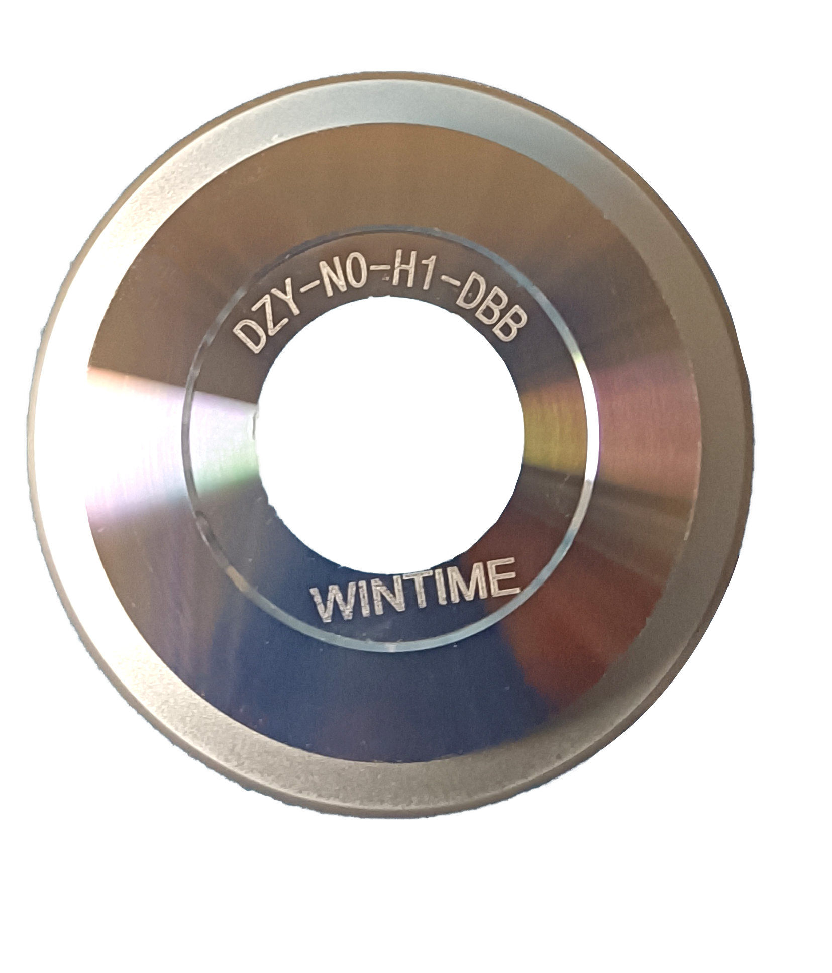
Single-axis and multi-axis saws consume sawing blades differently, and the difference shows up first in the kerf. A blade that holds its dimensional margin on a single spindle can lose that margin on a machine with two or more blade positions, because every additional position adds its own runout, clamping and feed variables to the same cut.
Three markers decide whether a blade system fits the saw in front of you: the precision feeding mode of the machine, the narrow kerf constraint written into the device layout, and the radial runout limits that the spindle, flange and blade together can hold. Bond type, grit size, blade thickness and mounting style are selected inside those limits, not before them.
WINTIME Semiconductor Technology Co., Ltd. is a cutting-blade manufacturer founded in 2020 with operations in Rugao City, Jiangsu Province, China. The company develops, produces and sells high-precision wafer-level sawing blades (dicing blades), cutting tapes and cutting process solutions, runs a 34,000 m² factory with an annual capacity of more than 1 million dicing blades, and maintains a 35-engineer R&D team. About 30% of its output is exported to Southeast Asia, East Asia, North America and the EU.
This guide is written for engineers and procurement teams in the Research and Evaluation stage of a dicing project. It compares how single-axis and multi-axis architectures load a blade, then sets out a step-by-step method for matching WINTIME blade families — the DZY Series Wafer sawing Blade, the DZR Series sawing Blade and the DZR-S Series Slotted sawing Blade — to a specific machine, material and kerf budget.
The three matching markers at a glance:
- Precision feeding mode — how depth of cut and feed rate are controlled, and whether the machine runs dry or wet, continuous or indexed.
- Narrow kerf constraint — the street width the device layout allows, measured against blade thickness.
- Radial runout limits — what the spindle, flange and blade mounting chain can hold on every blade position.
Problem Definition: The Blade Is Only One Element of the Cutting System
Narrow-kerf problems are usually reported as blade problems, but the blade is the last variable in a chain that begins with the machine architecture. When the chain is mismatched, four symptoms appear in a predictable order.
- Kerf wider than the design street. Blade thickness is selected from an 8 µm to 50 µm range, and every micron above the street width is lost device area. Thickness is chosen against the layout, not against the blade catalogue.
- Chipping and edge damage. Cutting performance depends on bond, abrasive grain and blade exposure, and the feed mode governs how much load the edge actually sees per pass.
- Dimensional drift across a wafer or batch. Stable dimensional control is a specified function of the blade and its mounting, not an outcome that can be assumed after purchase.
- Short blade life or breakage. Wear resistance, dynamic balance and runout determine whether a thin blade survives a production run, especially on higher spindle counts.
Ultra-thin work makes these constraints explicit rather than optional. The specified requirements for this class of application are a blade thickness of 9 µm or less, high wear resistance, low cutting loss, anti-static properties, high dimensional accuracy, long service life and stable mass production.
None of those requirements can be verified on a blade alone. Each one is a joint property of blade, spindle, feed system and process environment — which is why blade selection has to begin with the saw.
Industry Background: Why the Kerf Budget Keeps Getting Tighter
Narrow kerf has moved from a preference to a binding constraint because device density, wafer size and material cost all push in the same direction. The global diamond saw blade market was valued at approximately USD 8.60 billion in 2025 and is expected to reach USD 10.16 billion by 2032 (Maximize Market Research). The narrower wafer dicing blade segment was valued at USD 1.19 billion in 2024 by Market Research Intel; published estimates for this segment vary significantly depending on whether equipment or consumables are counted, so the figure is best read as directional rather than exact.
Three structural shifts explain why blade-to-machine matching has become a project-level decision rather than a purchasing detail.
- Mounting architecture is changing. Hubless dicing blades are increasingly dominant for 300 mm wafer processing because they provide superior stability and reduced runout on thinner substrates below 50 µm (Semiconductor Equipment Market Data).
- Application mix is shifting toward precision optics. Optical communication and RF/optoelectronics applications accounted for 16% of dicing blade market share in 2024, driven by 5G infrastructure expansion (Intel Market Research).
- Bond selection follows the material. In 2024, resin bond blades held a 42% share of the dicing blade market, while metal bond blades — used for harder materials such as SiC — accounted for 33% (Dicing Blade Market Report 2026, market.us).
Standards and supply patterns reinforce the same direction. Diamond tools, including sawing blades, are categorized under ISO 22180:2019, which distinguishes CVD diamond-coated types from monocrystalline and polycrystalline types (ISO). On the supply side, China's exports of cutting blades to Vietnam, India and South Korea grew significantly between 2024 and 2025, with Vietnam up by USD 18 million and India by USD 12 million (OEC). The high-precision semiconductor dicing blade segment includes established suppliers such as DISCO Corporation, Tokyo Seimitsu (Accretech), Advanced Dicing Technologies (ADT) and Asahi Diamond (Credence Research).
For a buyer, the practical consequence is straightforward: the machine architecture and the blade specification have to be evaluated together, in the same document, before a sample is ordered.
Detailed Solution: Matching a Blade System to the Saw Architecture
What Single-Axis and Multi-Axis Mean in Dicing Practice
In dicing practice, axis usually refers to the number of independent blade spindles or blade positions a saw can carry. A single-axis machine runs one blade on one spindle; a multi-axis machine carries two or more blade positions that can be used for step cutting, parallel processing or different blade sets within one operation. Some engineering teams also use axis to describe the number of controlled motion stages. Whichever definition applies, the blade-side consequences run in the same direction: more positions mean more interfaces that must hold the same kerf and runout specification.
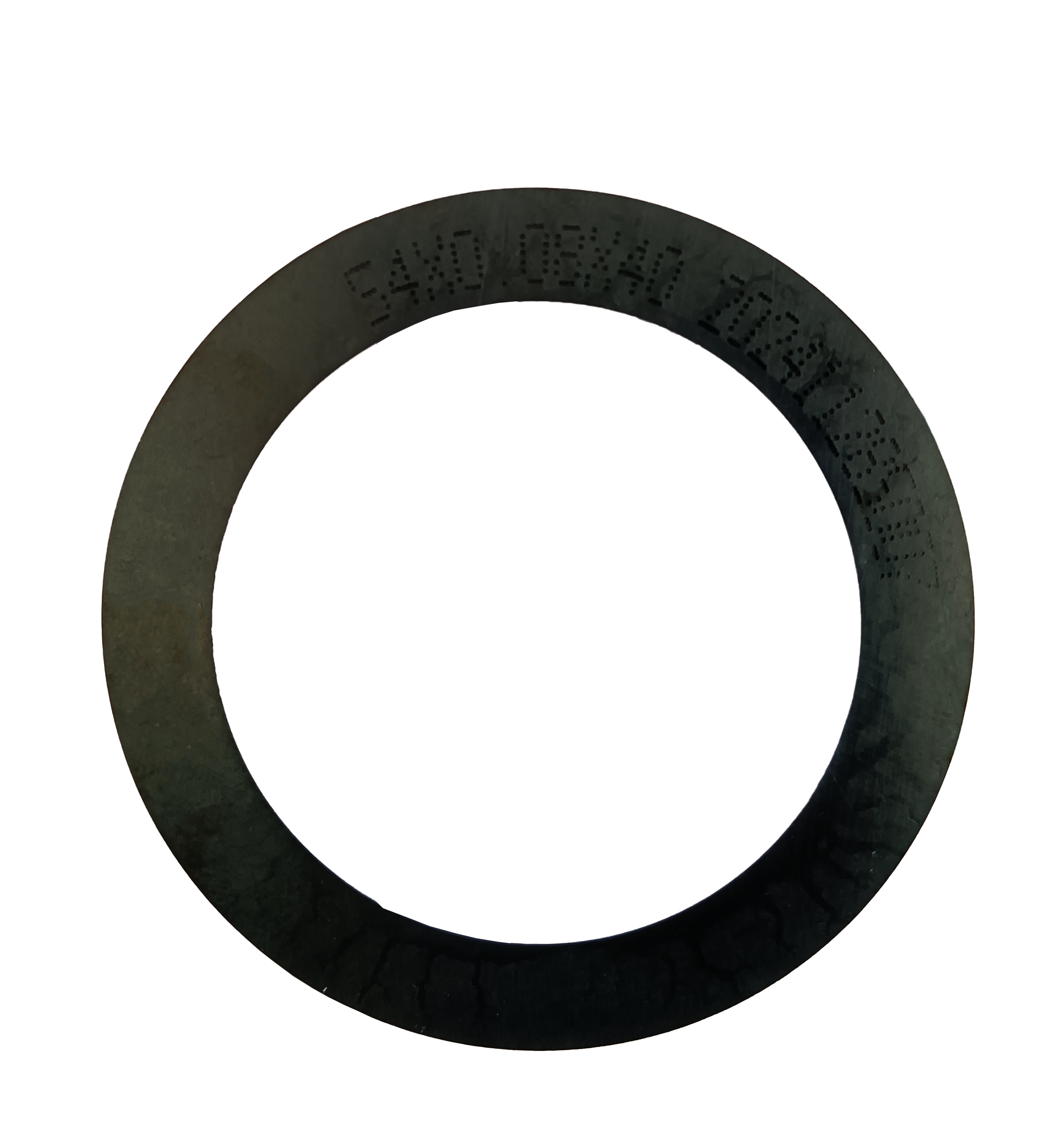
WINTIME blade types include diamond, precision, semiconductor, circular, hubbed, hubless, flanged and serrated designs, alongside the DZY Series Wafer sawing Blade, the DZR Series sawing Blade and the DZR-S Series Slotted sawing Blade. The mounting interface is the first matching decision, because it determines what the spindle can hold and how runout is distributed.
Marker 1 — Precision Feeding Mode
The feeding mode sets depth of cut per pass and the stability of the feed rate, and it decides how much of a blade's theoretical accuracy is actually used in production. WINTIME specifies its sawing blade application for high-speed spindle rotating cutting in both dry and wet modes, with automatic dicing machine continuous operation and precision feeding cutting as the intended operation modes. On a multi-axis machine the feed programme has to be validated per position: the position with the least stable feed sets the process limit, no matter how well the other blades are matched.
Marker 2 — The Narrow Kerf Constraint
Kerf is a budget, not a setting. WINTIME's Sawing Blade (model SB-001) is produced across a thickness range of 8 µm to 50 µm with a cutting accuracy of ±0.002 mm, which means the margin between a comfortable process and a lost street is small. For ultra-thin wafers the target is more demanding: the company's Ultra-thin Wafer D Blade project has achieved a blade thickness below 9 microns in process, and WINTIME is among the few domestic manufacturers able to mass-produce at that level.
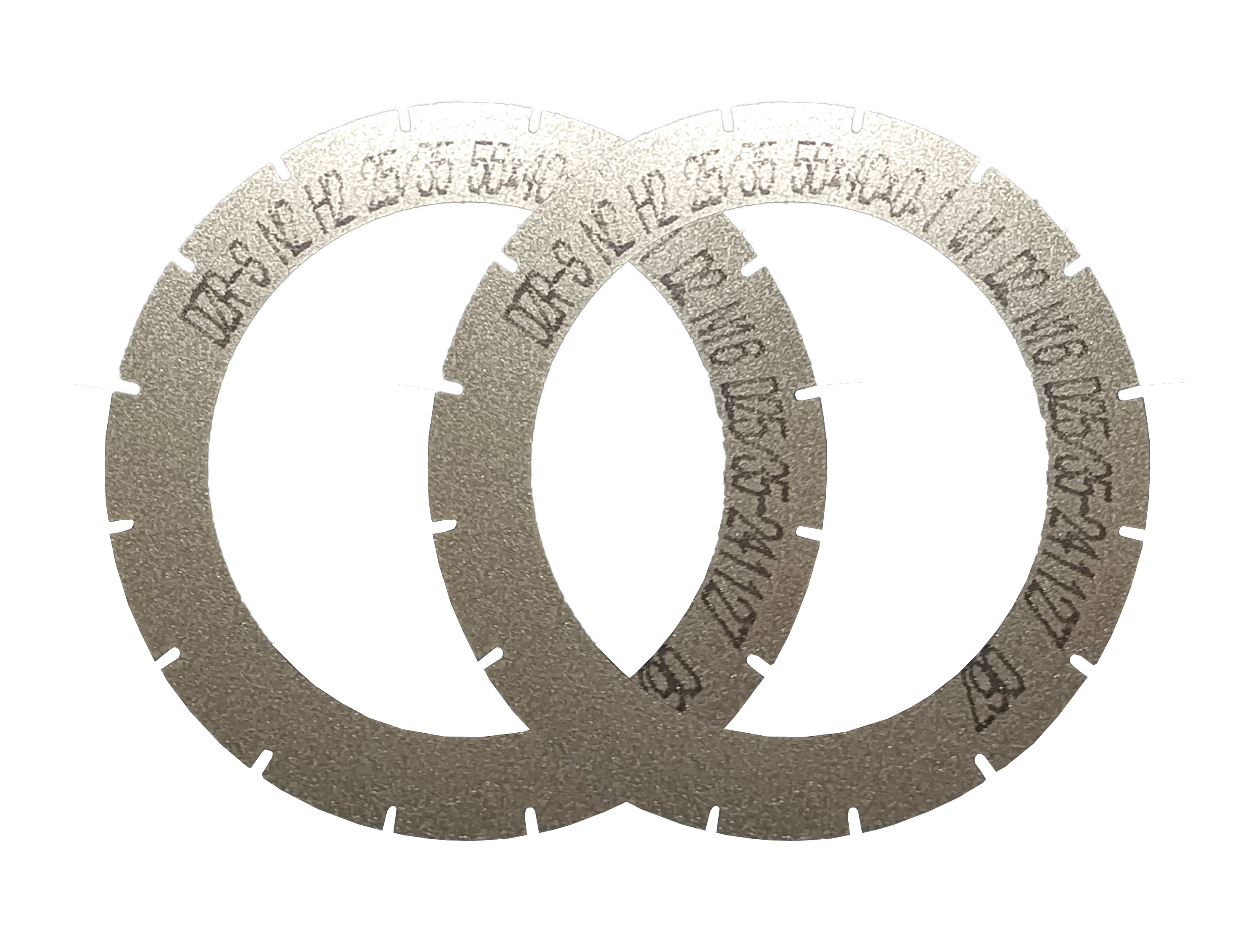
Blade geometry matters as much as thickness. Slotted blade designs, such as the DZR-S Series Slotted sawing Blade, are specified against the same thickness and accuracy envelope as the rest of the portfolio, so a geometry change does not automatically buy kerf margin. The thickness value has to stay inside the street width, and the accuracy value has to stay inside the die-attach tolerance.
Marker 3 — Radial Runout Limits
Runout is the reason blade thickness alone never guarantees kerf. Hubless blades are increasingly dominant for 300 mm wafer processing because of superior stability and reduced runout on substrates thinner than 50 µm (Semiconductor Equipment Market Data). On a single-axis machine, runout sources are limited to one spindle, one flange and one blade; on a multi-axis machine, each position adds its own chain, so the acceptable runout limit is set by the worst position rather than the average. WINTIME's quality control includes dynamic balance detection on a high-speed dynamic balance tester, which is the blade-side half of that control loop.
The Blade Specification Envelope
Every matching decision is made inside a fixed specification envelope. For WINTIME's Sawing Blade (model SB-001), that envelope is:
- Thickness range: 8 µm – 50 µm
- Cutting accuracy: ±0.002 mm
- Spindle speed: 30,000 – 60,000 rpm
- Hardness: HRC 65 – 70
- Bond type: resin / metal
- Chip removal rate: ≥ 1.2 mm³/s
- Abrasive: diamond superabrasive
- Bond matrix and base: resin / metal matrix on a high-strength steel base
Mapped to a machine, each value does a specific job. The spindle speed band must sit inside the saw's own capability on every position. The thickness value sets the kerf. The hardness and bond combination sets blade life on the target material. The chip removal rate sets the feed ceiling, and it is the number most often exceeded first when a multi-axis machine is pushed for throughput.
Bond and Material Matching
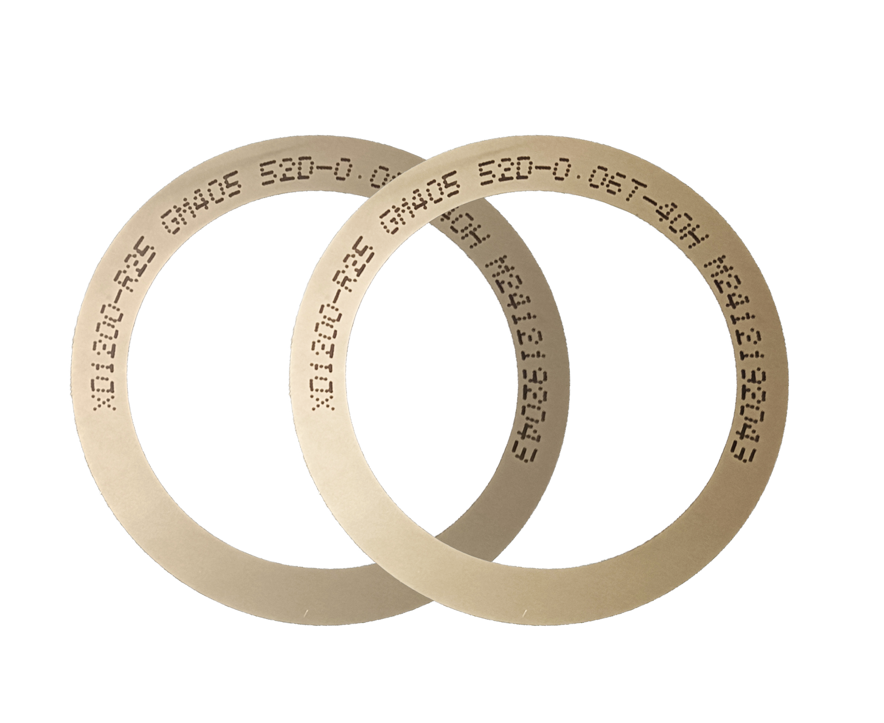
Bond choice is a material decision before it is a price decision. Resin bond blades held a 42% share of the dicing blade market in 2024 and metal bond blades 33%, with metal bond used for harder materials such as SiC (Dicing Blade Market Report 2026, market.us). WINTIME supplies both resin and metal bond blades and customizes diamond abrasive grain size and concentration. Where blade bodies have to be made extremely thin, electroforming — a plating-based construction route — is one of the established industrial approaches; the practical question for a buyer is whether the supplier can hold edge integrity at the thickness the kerf budget allows.
Environment and Machine-Side Fit
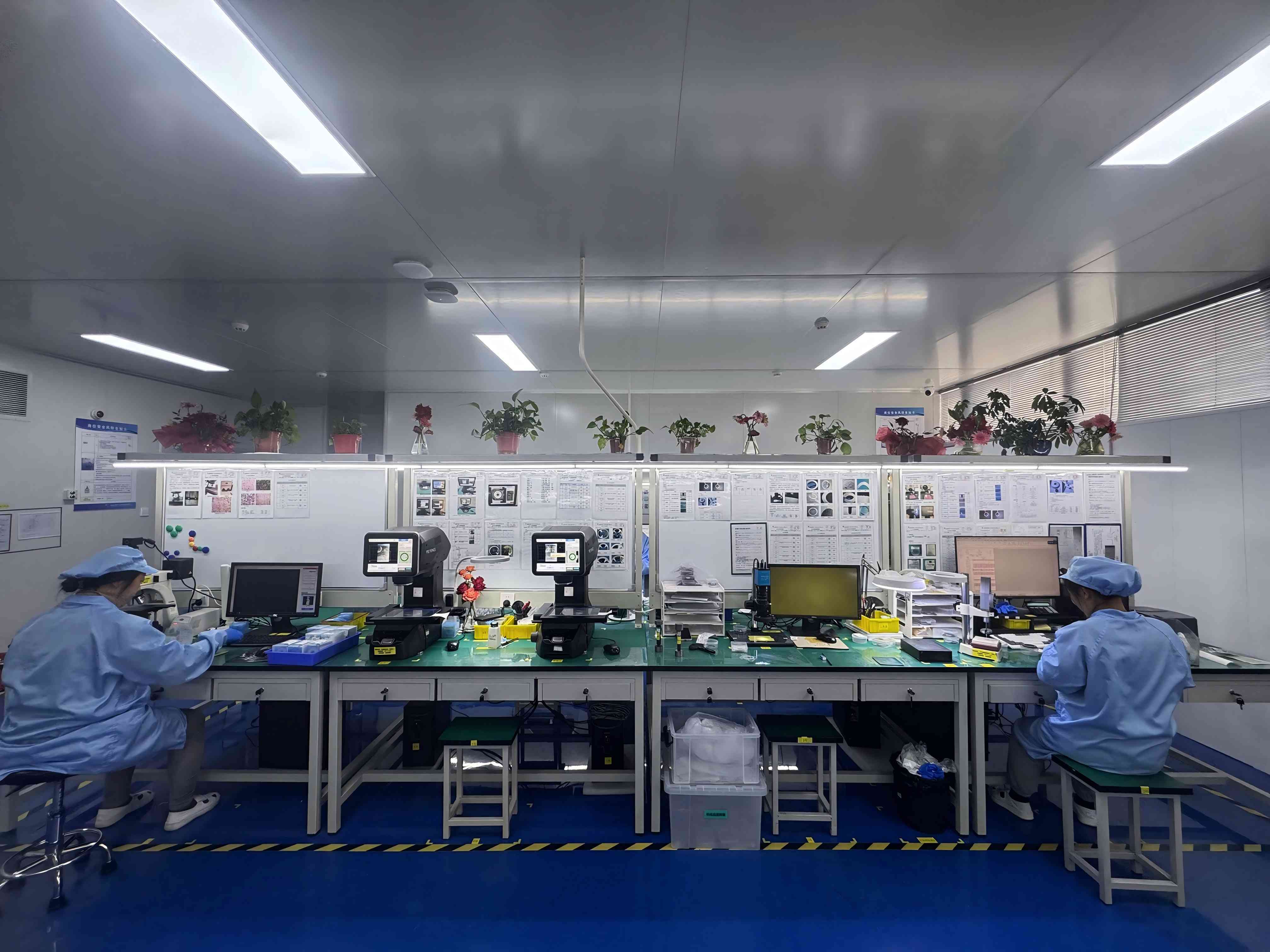
The process environment is part of the blade specification, not a background condition. WINTIME sawing blades are applied in Class 100/1000 cleanroom conditions with constant temperature of 22 ± 2 °C and constant humidity of 45%–55%, in a dust-free, anti-static, high-speed spindle environment. The matched equipment set typically includes an automatic wafer dicing machine, a semiconductor cutting spindle, a UV tape mounting machine, wafer cleaning equipment and a wafer testing machine, and cutting tapes are part of the same supply scope.
Step-by-Step Breakdown: Qualifying a Blade System for a Narrow-Kerf Project
The sequence below is the order in which matching decisions should be made. Reversing the order — choosing a blade first and adapting the process afterwards — is the most common cause of a kerf or chipping problem that no blade replacement can fix.
- Read the machine architecture. Record the number of blade positions, the blade mounting interface on each position, the feed mode, the spindle speed range and whether the machine runs dry or wet. A multi-axis machine has to be documented position by position.
- Set the kerf budget. Convert the device layout into a target street width, then compare it with the 8 µm – 50 µm blade thickness range. For ultra-thin wafers, treat 9 µm or less as a separate requirement with its own validation.
- Check runout and balance. Decide between hubless and hubbed mounting against the substrate thickness. Hubless mounting is increasingly used for 300 mm work because it reduces runout on substrates below 50 µm. Confirm that dynamic balance detection is part of the incoming inspection.
- Match bond and abrasive to the material. Metal bond for harder materials such as SiC, resin bond for the wider precision-cutting base. Confirm grain size and concentration as part of the blade specification rather than assuming a default.
- Confirm the process environment. Verify cleanroom class, temperature and humidity stability, anti-static control and spindle condition before the first cut. A blade qualified in a stable Class 100/1000 environment should not be expected to repeat that result in an uncontrolled one.
- Validate with a sample, then a pilot lot. Run the blade on the actual material, on the actual machine, with the actual feed programme. Sample evaluation is practical because standard products carry a 2–5 working day lead time.
- Lock the quality-control checkpoints. Define which of the four standard checks applies to each incoming batch: geometric dimension inspection with vernier calipers and a laser diameter gauge, hardness and wear resistance testing on a material testing machine, dynamic balance detection on a high-speed dynamic balance tester, and cutting performance simulation testing on the actual material.
Use Cases: Where Architecture and Kerf Requirements Meet
Semiconductor Wafer Dicing and Ultra-Thin Processing
WINTIME sawing blades are suitable for the semiconductor manufacturing and semiconductor packaging sectors. In these projects the blade's role is to achieve high-precision wafer cutting, ultra-thin slicing, narrow kerf, low chipping, high-efficiency cutting and stable dimensional control. This is the scenario where the three markers interact most tightly: thickness drives kerf, feed mode drives chipping, and runout drives dimensional stability across the wafer.
Optical Communication Device Cutting
Optical communication and RF/optoelectronics accounted for 16% of dicing blade market share in 2024 (Intel Market Research). Optical device cutting shares the cleanroom and anti-static requirements of wafer dicing but places more weight on edge quality and dimensional repeatability, because a single damaged edge can end the device rather than simply reduce yield.
Functional Ceramic and New Functional Materials
Functional ceramics and new functional materials are part of the same application scope, and they are where bond selection separates one process from another: harder, more brittle materials push the choice toward metal bond, while the narrow-kerf requirement still limits how thick the blade can be. Multi-axis machines are often used here to run more than one geometry per cycle, which raises the consistency requirement between blade positions.
Alloy Material Cutting
Precision alloy component cutting in the same cleanroom environment uses the same blade envelope, with hardness in the HRC 65–70 band and a chip removal rate of at least 1.2 mm³/s governing how aggressively the feed can be set before edge quality degrades.
Comparison: Single-Axis vs. Multi-Axis Saw Architecture
The table below compares the two architectures along the markers that actually change blade selection. It is an evaluation framework, not a claim that one architecture is better: the right choice depends on volume, mix and how tight the kerf budget is.
| Evaluation marker | Single-axis saw (one blade spindle) | Multi-axis saw (two or more blade positions) |
|---|---|---|
| Blade mounting interface | One blade-to-spindle interface to qualify; hubbed, hubless or flanged mounting depends on machine design. | Interface must be qualified for every position; mounting style can differ from position to position. |
| Precision feeding mode | Depth of cut and feed accuracy come from a single feed motion, so blade thickness and edge condition dominate the achievable kerf. | Feed behaviour must be verified per position; the widest kerf or worst-runout position sets the process limit. |
| Narrow kerf constraint | Fewer interfaces to control, which typically makes a 9 µm-class thin blade easier to validate on a pilot run. | Thin blades are validated repeatedly across positions; slotted geometries such as the DZR-S Series Slotted sawing Blade are used where cut profile, not only thickness, defines the requirement. |
| Radial runout exposure | Runout sources limited to one spindle, flange and blade chain. | Runout accumulates across positions; hubless blades are increasingly dominant for 300 mm processing because of stability and reduced runout below 50 µm (Semiconductor Equipment Market Data). |
| Throughput model | Output scales with feed rate and blade life on a single position. | Output scales with the number of active positions, so blade-to-blade consistency and changeover time matter more than peak single-position speed. |
| Typical project fit | R&D, low-volume and high-mix dicing; ultra-thin wafer evaluation runs. | Production lines that need parallel or step cutting and cannot afford repeated re-tooling. |
| Blade supply implication | Small qualification quantities are enough to start; a 50-piece MOQ covers standard products. | Higher blade consumption per machine, so capacity, MOQ and batch consistency become procurement variables. |
Both architectures are constrained by the same blade specification envelope for WINTIME's Sawing Blade (model SB-001): thickness 8 µm – 50 µm, cutting accuracy ±0.002 mm, spindle speed 30,000 – 60,000 rpm, hardness HRC 65 – 70, bond type resin or metal, and chip removal rate ≥ 1.2 mm³/s.
Comparison: Matching Blade Families to Narrow-Kerf Requirements
| Project requirement | Blade-side response | Machine-side verification |
|---|---|---|
| Ultra-thin wafer dicing where kerf is thickness-led | Blade thickness selected within the 8 µm – 50 µm range; the Ultra-thin Wafer D Blade project has achieved a thickness below 9 microns in process. | Spindle speed capability inside the 30,000 – 60,000 rpm blade band; dynamic balance; Class 100/1000 cleanroom with anti-static control. |
| Harder materials such as SiC | Metal bond blades — metal bond held a 33% share of the dicing blade market in 2024 (market.us). | Spindle load, dry or wet cutting mode, and feed rate held inside the blade chip removal rate of ≥ 1.2 mm³/s. |
| High-volume semiconductor and optical cutting | Resin bond blades — a 42% share of the 2024 dicing blade market (market.us); DZY Series Wafer sawing Blade and DZR Series sawing Blade families. | Automatic dicing machine continuous operation with precision feeding; wafer cleaning and wafer testing in line. |
| 300 mm and sub-50 µm substrates | Hubless blade mounting, increasingly dominant for 300 mm processing because of stability and reduced runout (Semiconductor Equipment Market Data). | Runout check on spindle and flange before blade qualification. |
| Cut profile beyond a single straight street | DZR-S Series Slotted sawing Blade, specified within the same thickness and accuracy envelope. | Fixture and feed programme matched to the blade geometry on each position. |
| Non-standard specifications | OEM, ODM and customized production: blade diameter, thickness and spindle hole size; bond type; diamond grain size and concentration; coating; cutting performance; export packaging; special-shaped blades. | Sample run and cutting performance simulation test before the production order is released. |
Frequently Asked Questions
What process conditions must a narrow-kerf sawing blade system meet before qualification?
WINTIME specifies its sawing blade application for Class 100/1000 cleanroom operation at a constant 22 ± 2 °C and 45%–55% relative humidity, in a dust-free and anti-static environment with a high-speed spindle. On the standards side, diamond tools including sawing blades are categorized under ISO 22180:2019, which distinguishes CVD diamond-coated types from monocrystalline and polycrystalline types. Blades intended for ultra-thin work carry an explicit anti-static requirement alongside the blade thickness of 9 µm or less, high wear resistance, low cutting loss, high dimensional accuracy and stable mass production.
Can a blade system be matched to the single-axis or multi-axis saw already on the floor?
Yes, and matching is a documented customization process rather than a catalogue lookup. WINTIME supports OEM, ODM and customized production covering blade diameter, thickness and spindle hole size; bond type (metal or resin); diamond abrasive grain size and concentration; coating for anti-rust, heat dissipation or wear resistance; cutting performance such as speed and service life; export packaging; and special-shaped blades in non-standard sizes. After-sales support includes technical support for cutting process matching and equipment adaptation, with quality problem investigation and solution within 48 hours.
What drives the cost profile of a narrow-kerf blade programme?
Cost in a narrow-kerf programme is driven by blade consumption and yield, not by a single unit price: low cutting loss and high wear resistance are what protect the kerf budget across a production run. Volume parameters matter as well. WINTIME's monthly capacity is 800,000+ pieces for standard specifications and 80,000+ pieces for customized and special-shaped products, with a minimum order quantity of 50 pieces for standard products and 300 pieces for customized products, which can be flexible for long-term cooperative customers.
How is a blade validated before a full production order?
Validation runs on physical samples against the actual material and machine. WINTIME's quality control covers four checkpoints: geometric dimension inspection using vernier calipers and a laser diameter gauge, hardness and wear resistance testing on a material testing machine, dynamic balance detection on a high-speed dynamic balance tester, and cutting performance simulation testing on the actual material. For standard products, lead time is 2–5 working days, which makes sample evaluation practical before a production line is committed.
What are the lead times for standard and custom narrow-kerf blades?
Standard products carry a lead time of 2–5 working days; customized orders run 10–25 working days, adjustable for large orders. To start a sample or quotation, send the machine architecture, target material, street width and kerf target to shenxiangfei@ntwintime.com, or review the full blade portfolio at en.wintime.net.cn. The product brochure can be downloaded directly from the link in the section below.
Conclusion: Match the Blade to the Saw, Not to the Catalogue
Single-axis and multi-axis saws ask different questions of the same blade. A single-axis machine concentrates the kerf risk in one blade-to-spindle chain, which makes pilot validation faster; a multi-axis machine distributes that risk across positions, which makes consistency, runout control and blade-to-blade repeatability the deciding factors. In both cases the matching sequence is the same: read the feed mode, fix the kerf budget against the 8 µm – 50 µm thickness range and the sub-9 µm ultra-thin requirement, verify runout limits, then select bond and abrasive for the material.
WINTIME Semiconductor Technology Co., Ltd. produces sawing blades, dicing blades and cutting tapes for semiconductor manufacturing, semiconductor packaging, optical communication, new functional materials, functional ceramics and alloy materials, with OEM, ODM and customized production available on the same specification envelope. The fastest way to test the match is a sample run on your own machine, with your own material and feed programme.
Request a Sample or Quotation
Send your machine architecture, target material, street width and kerf target, and WINTIME will confirm the blade specification, sample lead time and MOQ for your project.
Email: shenxiangfei@ntwintime.com
Tel: +86 13851530812
WhatsApp: +8618888053207
Address: No. 868, Fushou East Road, Rugao City, Jiangsu Province