
Solving Blade Wear and Kerf Drift in High-Volume Wafer Dicing: A Sawing Blade Action Plan
A dicing line rarely fails all at once. The first sign of a blade that is losing its edge is usually a kerf that creeps wider from lot to lot, followed by chipping along the die street, and only at the end a blade change that stops the machine mid-shift. By then the cost has already been paid in yield and unscheduled downtime, not in the price of the blade.
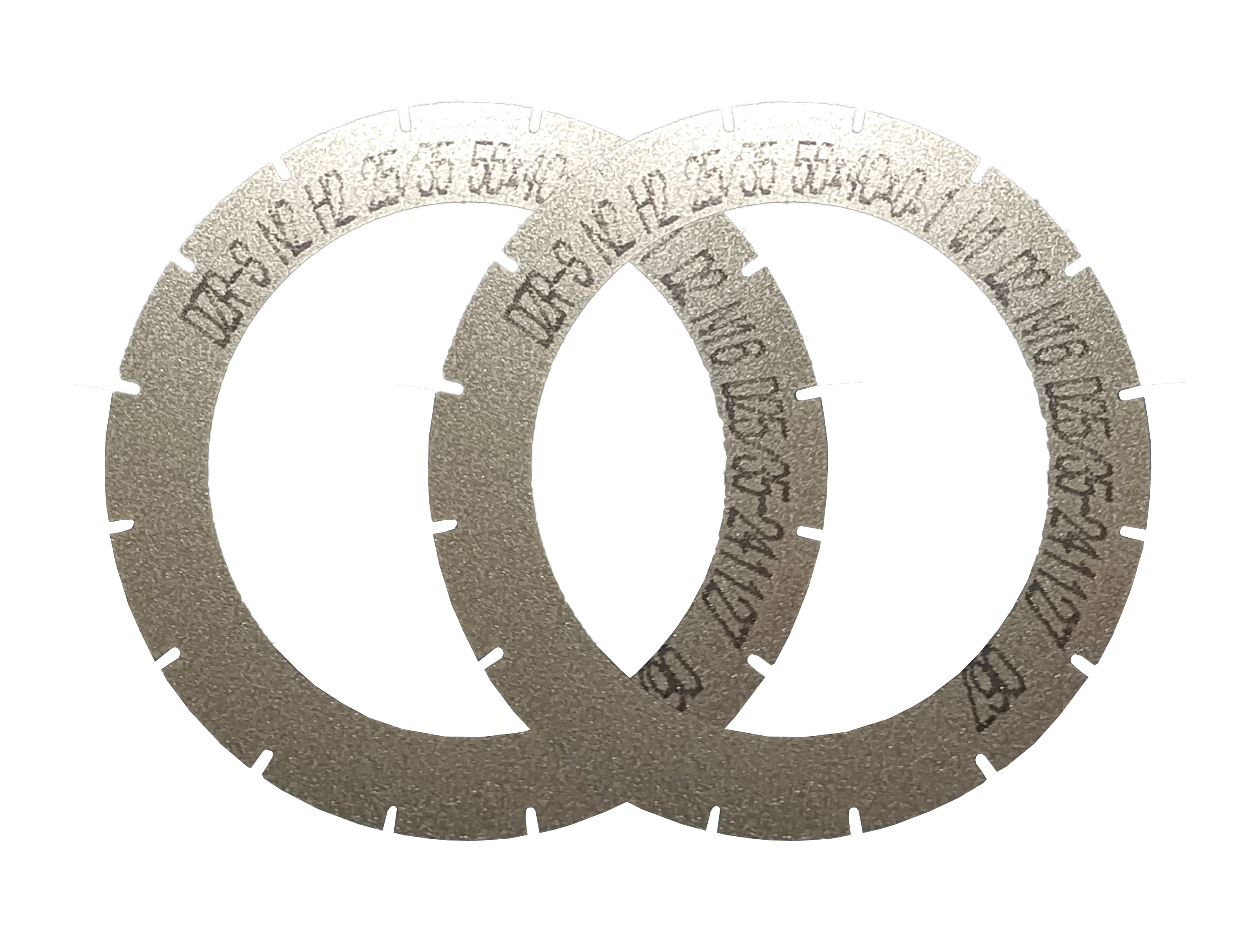
Blade wear and kerf drift in high-volume wafer dicing are best solved together, because they share one root cause: a cutting edge that cannot hold its geometry while removing material at production speed. The corrective action is a specification decision first and a process decision second. A Sawing Blade built for high wear resistance, low cutting loss and stable mass production behavior is designed to hold its specified cutting accuracy of ±0.002 mm across continuous operation rather than drifting early in the run.
WINTIME Semiconductor Technology Co., Ltd. is a manufacturer established in 2020 in Rugao City, Jiangsu Province, China, specializing in the research, development, production and sales of high-precision cutting blades, including Sawing Blades and Dicing Blades. Its Sawing Blade range covers the DZY Series Wafer Sawing Blade, the DZR Series Sawing Blade and the DZR-S Series Slotted Sawing Blade, in both hubbed and hubless formats.
This action plan follows the order a production engineer meets the problem: what wear and kerf drift actually are, why continuous high-volume cutting makes both worse, which blade specifications control them, a six-step plan for stabilizing the process, where the plan applies, and the buyer questions that decide whether it holds in mass production.
Blade Wear and Kerf Drift: Two Symptoms, One Failure Curve
Blade wear is the progressive loss of cutting capability at the blade's working edge: abrasive grains dull or are pulled from the bond matrix, and the bond itself erodes. In production terms, wear reads as a blade that needs more spindle effort to remove the same amount of material.
Kerf drift is different, and more dangerous. It is the gap between the kerf width the process was set up to produce and the kerf width the blade actually produces, measured across a run rather than on a single wafer. A drifting kerf still cuts. The machine keeps producing, and the deviation surfaces downstream in die spacing, package singulation or a dimensional check on finished parts.
The two behave as one system. As the edge wears, the cut becomes less clean, load rises, and dimensional control loosens. Unless kerf is measured as a trend, wear is read as "the blade is getting old" instead of as a dimensional failure that a different specification could have contained.
Four signals, read together, tell you whether the process is drifting before the kerf specification is breached:
- Kerf width measured per lot against the process target, not only at setup;
- Chipping along the die street, which typically appears before the kerf measurement moves;
- Spindle load trend across a blade's service life, where rising load is an early wear indicator;
- Blade change interval, which shortens as wear accelerates.
Why Continuous High-Volume Dicing Accelerates Both Problems
The wafer dicing blade market was valued at USD 1.19 billion in 2024, with growth driven by semiconductor miniaturization and the adoption of 300 mm wafers (Market Research Intel). The broader diamond saw blade category that includes sawing blades was valued at approximately USD 8.60 billion in 2025 and is projected to reach USD 10.16 billion by 2032 (Maximize Market Research). Those figures describe volume: more wafers, more cuts, more blade revolutions per shift.
Blade selection has become more precise along with that volume. Resin bond blades held a 42% share of the dicing blade market in 2024, while metal bond blades — used for harder materials such as SiC — accounted for 33% (market.us). For a production engineer, that split is above all a wear decision: bond type determines how the abrasive is retained, and therefore how the edge behaves after thousands of cuts rather than hundreds.
Construction has followed the same logic. Hubless dicing blades are reported to be increasingly dominant for 300 mm wafer processing because of their stability and reduced runout on thinner substrates below 50 µm (Semiconductor Equipment Market Data). Thinner workpieces leave less margin for runout, so the format becomes part of kerf control rather than a machine-room preference.
The application mix reinforces the point. Optical communication and RF/optoelectronics applications accounted for 16% of dicing blade market share in 2024, a value of USD 69.9 million, supported by 5G infrastructure expansion (Intel Market Research). Optical device cutting is a kerf-sensitive application, which means drift shows up quickly in optical performance rather than only in yield.
Supply chains are shifting too. China's exports of cutting blades to Vietnam rose by USD 18 million and to India by USD 12 million between 2024 and 2025 (OEC) — a movement that places more dicing capacity in markets still building their process baselines, where a wear-management plan matters more than a blade catalog.
The competitive landscape for high-precision semiconductor dicing blades includes suppliers such as DISCO Corporation, Tokyo Seimitsu (Accretech) and Advanced Dicing Technologies (ADT) (Credence Research). That co-existence is useful context for buyers: specification discipline, not brand familiarity, is what makes a dicing line repeatable.
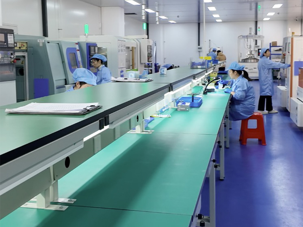
Finally, high-volume dicing is an environment-controlled process. Sawing blade applications operate in Class 100/1000 clean rooms at a constant temperature of 22±2°C and constant humidity of 45%–55%, in dust-free and anti-static conditions with high-speed spindles. Temperature and humidity excursions change how both the blade and the mounting tape behave, which is why the clean room envelope belongs in the same checklist as the blade specification.
The Specification Set That Controls Wear and Kerf
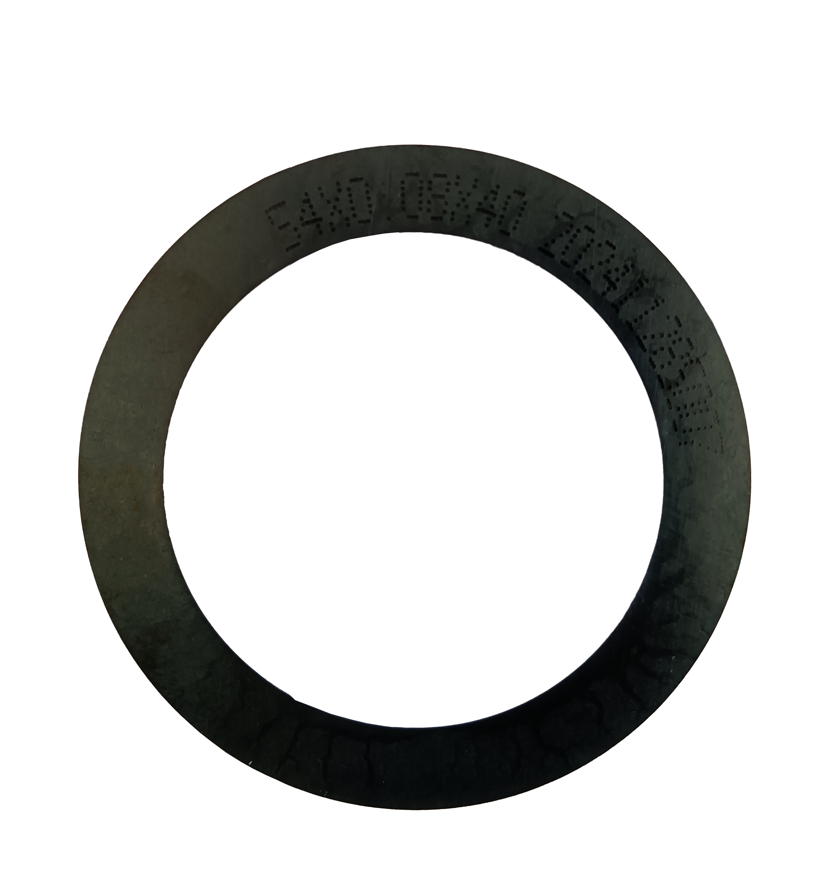
Wear resistance, low cutting loss and stable mass production are the three requirements a high-volume dicing blade has to satisfy at the same time. On the WINTIME SB-001 Sawing Blade, those requirements are expressed as a published specification set.
| Specification | Published value | What it governs in production |
|---|---|---|
| Blade thickness range | 8 µm – 50 µm | Kerf width, and therefore material loss per die |
| Cutting accuracy | ±0.002 mm | The dimensional window the blade is specified to hold across a run |
| Spindle speed range | 30,000 – 60,000 rpm | The qualified operating window for high-efficiency cutting |
| Hardness | HRC 65–70 | Blade body rigidity under continuous high-speed load |
| Bond type | Resin / metal | Wear behaviour and material compatibility |
| Chip removal rate | ≥1.2 mm³/s | Debris evacuation, where re-cutting amplifies wear |
| Construction | Diamond superabrasive on a resin or metal bond matrix, with a high-strength steel base | Abrasive source and blade body |
| Series coverage | DZY Series Wafer Sawing Blade, DZR Series Sawing Blade, DZR-S Series Slotted Sawing Blade; hubbed and hubless formats | Matching blade format to material and equipment |
Thickness is where kerf and wear meet. A blade at the thin end of the 8 µm–50 µm range removes less material, which reduces cutting loss directly; the same thin blade also has less body to carry load, so the engineering task is to select the thinnest blade that still holds the required accuracy and service life for the workpiece — not the thinnest blade available. WINTIME's "Ultra-thin Wafer D Blade" project achieved a process thickness of less than 9 microns, and the company is one of the few domestic manufacturers capable of mass-producing ultra-thin wafer dicing blades.
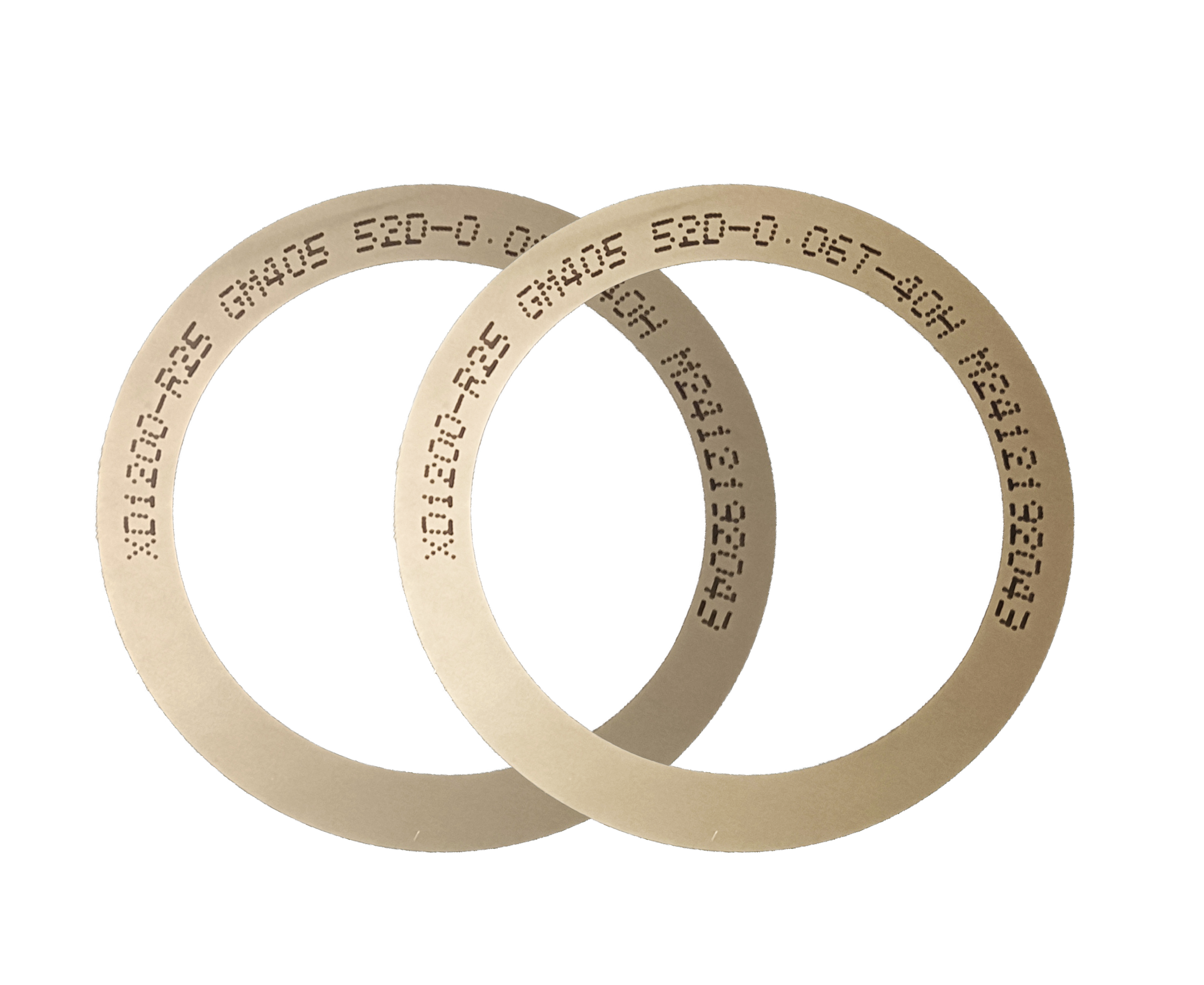
Cutting accuracy of ±0.002 mm is the number the drift-monitoring plan should be built around: it defines how far the achieved kerf may move from target before the process is running outside what the blade is specified to deliver. Spindle speed of 30,000–60,000 rpm defines the qualified window for high-efficiency cutting; running above that window to chase throughput is a common way to buy short-term output with long-term kerf control.
Hardness is specified at HRC 65–70, describing a blade body stiff enough to resist deflection during continuous high-speed cutting. Bond type is a binary decision with a material answer: resin bond for standard semiconductor wafer and package work, metal bond when the workpiece is harder, as with SiC. Chip removal is specified at ≥1.2 mm³/s, because debris that is not evacuated is re-cut by following revolutions, and re-cutting is one of the mechanisms that turns a sharp edge into a worn one.
The Action Plan: Six Steps to Stabilize Kerf and Blade Life
The specification set is a prerequisite, not the whole answer. The following plan is written for a production engineer running automatic dicing machines continuously, and each step converts part of the specification into a measurable process control.
- Fix the kerf acceptance window before the run starts. Write the target kerf and its tolerance into the process sheet, using the blade's specified cutting accuracy of ±0.002 mm as the reference for what the blade is expected to hold. A drift problem cannot be detected against a target that is only known informally.
- Match bond type and blade format to the material. Resin bond for semiconductor wafer and package singulation work; metal bond where the workpiece is harder, including SiC. Use a hubless format where reduced runout and stability on thin substrates matter — the format now increasingly used for 300 mm wafer processing.
- Run inside the qualified spindle window. The specified range is 30,000–60,000 rpm. Exceeding it raises removal rate in the moment and shortens the interval in which kerf stays inside tolerance.
- Control the environment, not only the machine. Class 100/1000 clean room conditions, 22±2°C, 45%–55% relative humidity, dust-free and anti-static. Both dry and wet cutting are supported; the mode the line is qualified for should be held constant through the run.
- Verify the matched equipment stack. The blade operates inside a system: automatic wafer dicing machine, semiconductor cutting spindle, UV tape mounting machine, wafer cleaning equipment and wafer testing machine. A wear problem can originate in tape behaviour or spindle condition rather than at the blade edge.
- Trend the wear, and validate on samples before scaling. Log kerf width, chip counts and spindle load per lot, and time the blade change from the trend line rather than from failure. Then confirm the specified behaviour on the buyer's own machine, material and tape before the blade goes into volume production.
Where This Action Plan Applies
The plan is material-agnostic but not application-agnostic. It applies wherever the cutting job is continuous and dimensional control is an acceptance criterion.
- Wafer dicing and scribing;
- Semiconductor package cutting;
- Ultra-thin wafer processing, including blades in the sub-9 µm range;
- Optical device cutting, where optical communication and RF/optoelectronics accounted for 16% of 2024 dicing blade market share (Intel Market Research);
- Ceramic substrate cutting, including functional ceramics;
- Precision alloy component cutting.
The industries in scope are semiconductor manufacturing, semiconductor packaging, precision electronic component processing and optical ceramic cutting, along with optical communication, new functional materials, functional ceramics and alloy materials. The application scenario is common in China, Japan, Korea, Singapore, Malaysia, the United States and Germany. WINTIME's own export business accounts for 30% of total sales, serving markets in Southeast Asia, East Asia, North America and the European Union.
Comparing Blade Configurations: Which Choice Fits Which Wear Problem
The table below compares configurations using the published WINTIME specification set and third-party market data. It does not score them, because the correct configuration is determined by the workpiece and the machine, not by a ranking.
| Configuration | What it is | Third-party context | Selection rule |
|---|---|---|---|
| Resin bond Sawing Blade | Bond matrix: resin; diamond superabrasive on a high-strength steel base | Resin bond blades held 42% of the dicing blade market in 2024 (market.us) | Starting point for semiconductor wafer and package cutting; confirm on a sample run |
| Metal bond Sawing Blade | Bond matrix: metal; diamond superabrasive on a high-strength steel base | Metal bond blades held 33% of the 2024 market and are used for harder materials such as SiC (market.us) | Choose when the workpiece material is harder |
| Hubless Sawing Blade | Hubless format within the WINTIME Sawing Blade range | Reported increasingly dominant for 300 mm processing due to stability and reduced runout below 50 µm (Semiconductor Equipment Market Data) | Choose for thin substrates and 300 mm work |
| Hubbed Sawing Blade | Hubbed format listed in the WINTIME Sawing Blade range | No comparable third-party figure available | Choose where the spindle and flange system is designed around a hub |
| DZR-S Series Slotted Sawing Blade | Slotted series within the DZY / DZR / DZR-S family | No comparable third-party figure available | Choose where the application calls for a slotted format; confirm by sample run |
Two limits are worth stating plainly. First, market share describes the installed base, not suitability for a specific workpiece. Second, thickness and accuracy interact: a thinner blade reduces cutting loss but narrows the margin available for load and runout, so the thickness decision should be made against the machine's spindle window, the tape in use, and the dimensional tolerance the finished part must meet. Diamond tools, including sawing blades, are categorized under ISO 22180:2019, which distinguishes CVD diamond-coated from monocrystalline and polycrystalline types — a classification worth recording when a blade is specified against a customer requirement.
FAQ: Wear, Kerf Drift and Volume Supply
Are there standards or clean room conditions that high-volume dicing lines need to document?
Two layers of compliance matter. The first is the blade standard: diamond tools, including sawing blades, are categorized under ISO 22180:2019, which distinguishes CVD diamond-coated types from monocrystalline and polycrystalline types — a classification worth keeping in the supplier file because it describes how the diamond layer was formed. The second is the operating environment: sawing blade applications are commonly run in Class 100/1000 clean rooms at a constant temperature of 22±2°C and constant humidity of 45%–55%, in dust-free and anti-static conditions with high-speed spindles. This scenario is common in China, Japan, Korea, Singapore, Malaysia, the United States and Germany, so a compliance file built in one market usually needs its local equivalent elsewhere.
Which Sawing Blade specifications actually reduce wear and kerf drift?
The governing set on the WINTIME SB-001 Sawing Blade is: thickness range 8 µm–50 µm, cutting accuracy ±0.002 mm, spindle speed 30,000–60,000 rpm, hardness HRC 65–70, resin or metal bond, and chip removal rate ≥1.2 mm³/s. The blade is built from diamond superabrasive on a resin or metal bond matrix with a high-strength steel base, and the series range covers the DZY Series Wafer Sawing Blade, the DZR Series Sawing Blade and the DZR-S Series Slotted Sawing Blade in hubbed and hubless formats. Thin-blade capability belongs in the same answer: the "Ultra-thin Wafer D Blade" project reached a process thickness of less than 9 microns, and WINTIME is one of the few domestic manufacturers able to mass-produce ultra-thin wafer dicing blades, supported by an R&D team of 35 engineers, 2 patent technologies and an annual production capacity of 1 million pieces.
How should a wear-and-kerf budget be structured?
Blade purchase price is the smallest line in the calculation. The cost of wear and kerf drift is carried by four others: blade consumption per wafer, material loss caused by kerf width, downtime for blade changes, and scrap from chipping or dimensional drift discovered downstream. Because the specification set is designed around low cutting loss and stable mass production behaviour, the useful comparison is cost per good die rather than cost per blade — which is why the thickness decision (8 µm–50 µm) and the accuracy figure (±0.002 mm) belong in the commercial model, not only in the process sheet. Qualification cost belongs there too: a blade that passes a sample run and then drifts in volume has already spent the budget it was meant to protect.
Can a Sawing Blade be validated on our own dicing machine before committing to volume?
Yes, and it should be. The blade operates as one part of a system — high-speed spindle rotating cutting, dry or wet cutting, continuous operation on automatic dicing machines, and precision feeding — so results depend on the machine, the mounting tape, cleaning and inspection as much as on the blade. A practical sample request states the workpiece material and thickness, the target kerf, the spindle speed window available on the machine, and the tape and cleaning equipment in use. The supporting equipment around the blade includes the automatic wafer dicing machine, semiconductor cutting spindle, UV tape mounting machine, wafer cleaning equipment and wafer testing machine; if any of these sits outside its qualified condition, the sample result will describe the line rather than the blade.
What does supply continuity look like for volume blade orders?
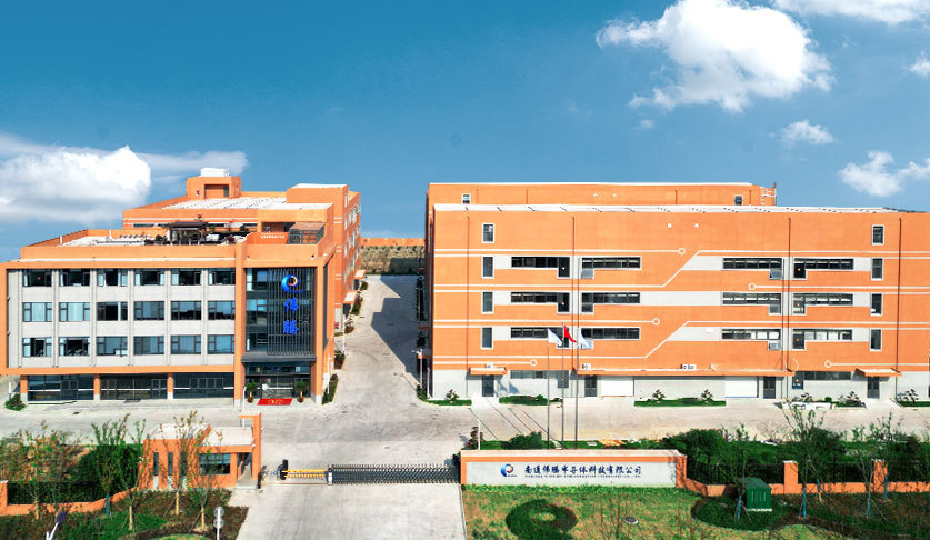
Volume dicing lines need a supplier whose capacity matches consumption. WINTIME operates a 34,000 ㎡ manufacturing facility with approximately 100 staff and an annual production capacity of 1 million pieces, backed by an R&D team of 35 engineers; the 2023 Nantong Wintime Semiconductor Special Materials Project involved a total investment of nearly tens of millions of yuan, and export business accounts for 30% of total sales across Southeast Asia, East Asia, North America and the European Union. The company was established in 2020 and is recognized by many leading enterprises at home and abroad as a supplier of high-precision cutting blades, cutting tapes and cutting solutions. To move from sample to scheduled supply, send the workpiece material, target kerf and machine window to shenxiangfei@ntwintime.com or call +86 13851530812 (WhatsApp: +8618888053207).
Conclusion: Make Wear a Controlled Variable, Not a Surprise
Blade wear and kerf drift are dimensional failures, not maintenance events. They are managed by choosing a blade whose specification was written for high wear resistance, low cutting loss and stable mass production — thickness between 8 µm and 50 µm, cutting accuracy of ±0.002 mm, a qualified spindle window of 30,000–60,000 rpm, HRC 65–70 hardness, the correct bond for the workpiece, and chip removal of at least 1.2 mm³/s — and then holding the process to that specification with kerf trending, environmental control and verified equipment.
WINTIME Semiconductor Technology Co., Ltd. produces Sawing Blades and Dicing Blades for semiconductor manufacturing, semiconductor packaging, precision electronic component processing and optical ceramic cutting, across the DZY, DZR and DZR-S series. Product information is available at en.wintime.net.cn.
Next Step: Sample, Kerf Trial or Volume Quote
Send your workpiece material, target kerf and spindle speed window, and WINTIME will match a Sawing Blade series and bond type for your machine.
Email: shenxiangfei@ntwintime.com | Tel: +86 13851530812 | WhatsApp: +8618888053207
Address: No. 868, Fushou East Road, Rugao City, Jiangsu Province, China
Product catalog (PDF, public download): WINTIME Sawing Blade catalog