
The Physics Behind Sawing: How an Ultra-Thin Blade Keeps Wafers Whole
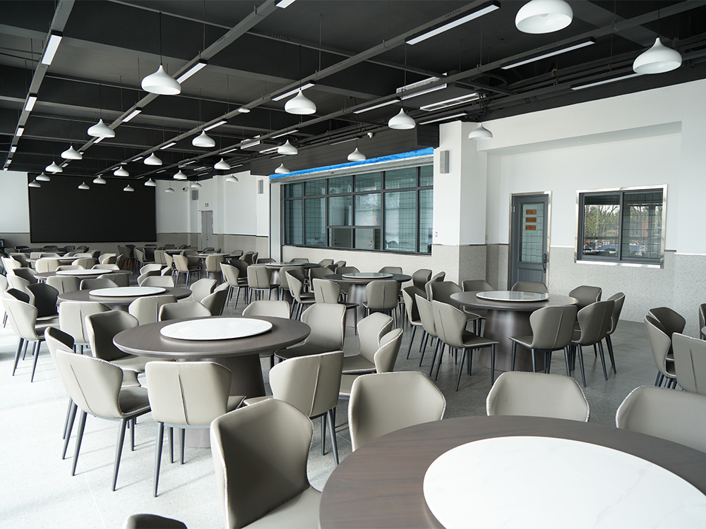
Inside the facility where the cutting variables are set: blade development and production for high-precision wafer sawing, WINTIME Semiconductor Technology Co., Ltd.
Short answer: A wafer stays whole when three things stay under control at the same moment — the mechanical load at the blade–material interface, the heat produced by friction inside the kerf, and the vibration that turns a straight cut into a fracture path. Blade thickness is only one input in that balance. Spindle speed decides how fast each diamond grit travels; bond hardness decides how much load each grit carries; the coolant decision decides how much heat leaves the cut; and a stable cleanroom decides whether any of it repeats from batch to batch.
This explainer treats ultra-thin wafer sawing as a physics problem rather than a catalogue problem. It covers the forces behind chipping and fracture, the role of spindle speed and blade exposure, the practical difference between dry and wet cutting, and why permanent cleanroom stability belongs in a purchasing decision rather than in the facility manager's notes. It closes with the comparison logic that helps a buyer at the decision stage evaluate a blade and a supplier together.
Problem Definition: Why Wafers Fracture During Sawing
Wafer breakage in dicing is rarely the result of one overload event. It is usually the result of several stress sources acting at the same time. Separating them is what makes blade and parameter selection predictable instead of experimental.
- Bending stress from blade deflection. A thinner blade cuts a narrower kerf and removes less material, but it also bends more easily. When deflection pushes the kerf wall sideways, the tensile stress concentrated at the cut edge is what starts a crack.
- Thermal stress from friction heat. Every diamond grit removes material through concentrated contact. Energy that is not converted into chip removal becomes heat at the interface, and the blade, the workpiece and the debris all respond differently to it.
- Sub-surface damage from grit impact. Individual grits strike brittle material at speed. The visible cut can look clean while micro-cracks beneath the surface become the starting point of a later fracture — during handling, lamination or back-end thermal processing.
- Vibration, runout and chatter. Periodic loading from an unbalanced or poorly mounted blade turns a steady cut into a repeating impact. This is where edge chipping and kerf drift usually originate.
A fifth and less visible factor is debris. Material removed from the kerf has to leave the cut. If it is re-cut instead, it behaves as an abrasive between blade and workpiece, adding load and heat that no parameter setting intended.
Industry Background: Why Ultra-Thin Cutting Became a Mainstream Constraint
Wafer dicing is no longer a niche process step. The global wafer dicing blade market was valued at USD 1.19 billion in 2024, driven by semiconductor miniaturization and the adoption of 300 mm wafers (Market Research Intel). The broader diamond saw blade market, which includes these tools, was valued at approximately USD 8.60 billion in 2025 and is expected to reach USD 10.16 billion by 2032 (Maximize Market Research).
Two structural shifts explain why the physics described in this article matters more now than it did a decade ago:
- Thinner substrates, larger diameters. Hubless dicing blades are increasingly dominant for 300 mm wafer processing because they offer superior stability and reduced runout on substrates thinner than 50 µm (Semiconductor Equipment Market Data). Larger and thinner wafers simply leave less mechanical margin before fracture.
- Harder and more specialised workpieces. Resin bond blades held a 42% share of the dicing blade market in 2024, while metal bond blades — used for harder materials such as SiC — accounted for 33% (Dicing Blade Market Report 2026). Different workpiece physics demand different bond behaviour.
Application demand is broadening at the same time. Optical communication and RF/optoelectronics applications accounted for 16% of the dicing blade market in 2024, worth USD 69.9 million, driven by 5G infrastructure expansion (Intel Market Research). On the supply side, China's exports of cutting blades to Vietnam, India and South Korea grew significantly between 2024 and 2025, with Vietnam increasing by USD 18 million and India by USD 12 million (OEC). Sourcing in this category is increasingly cross-border, which raises the value of verifiable process evidence.
The Detailed Solution: Where the Physics Is Actually Controlled
WINTIME Semiconductor Technology Co., Ltd. is a Jiangsu-based manufacturer, established in 2020, that integrates the research, development, production and sales of high-precision wafer-level cutting blades. The company supplies high-precision cutting blades, cutting tapes and complete cutting solutions, and serves customers in Southeast Asia, East Asia, North America and Europe. Its production base in Rugao City covers 34,000 ㎡, employs approximately 100 people, includes an R&D team of 35 engineers, and has an annual production capacity of more than 1,000,000 dicing blades.
From a physics standpoint, the relevant part of that description is not the size of the facility but what the facility makes possible: process control. A plant operating at this scale can standardise the variables that decide whether a blade keeps a wafer whole. WINTIME's "Ultra-thin Wafer D Blade" project has achieved a blade thickness of less than 9 microns, and the company is one of the few domestic manufacturers able to mass-produce at that level. WINTIME holds two patent technologies and has received awards in national, provincial and municipal science and technology and entrepreneurship competitions.
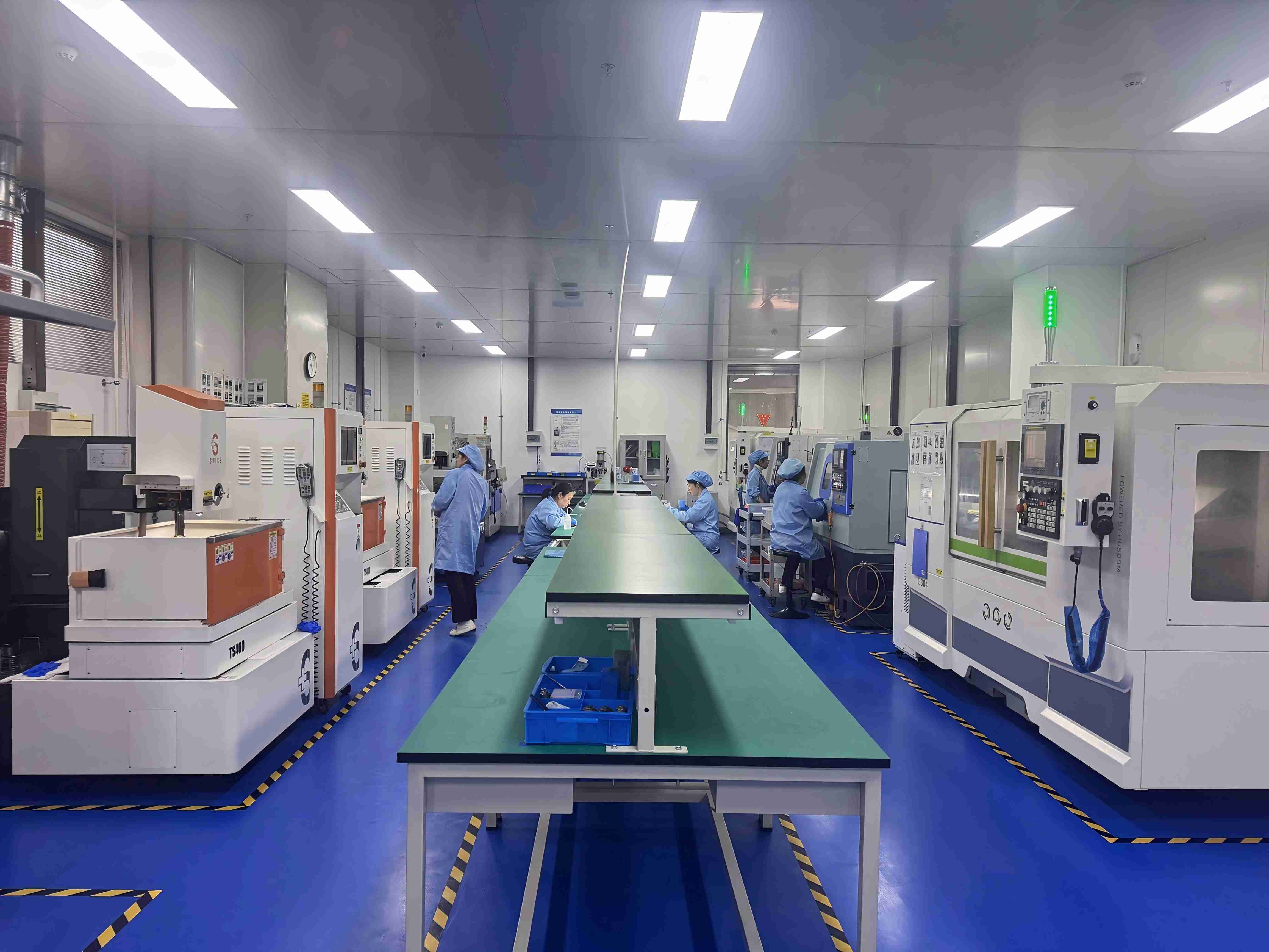
Standardised parameters and automated equipment are what make thin-blade behaviour repeatable.
Thin blades only behave predictably when production is repeatable. WINTIME addresses batch-to-batch variation — the risk that a blade validated during qualification performs differently in volume production — through three parallel measures. Production process parameters are standardised and automatic production equipment is used to avoid manual operation errors. Every production batch is recorded in a batch production data tracking system that logs all process parameters. And adjacent batches are compared through testing so that performance consistency can be confirmed rather than assumed.
On the quality side, the company implements an ISO 9001 quality management system and follows standard operating procedures, assigns dedicated quality inspectors to track each production batch, and maintains a batch quality file that can be traced at any time so that an unqualified batch can be recalled promptly if a problem occurs. For a buyer, this is the mechanism that connects an engineering principle — controlled forces — to an outgoing quality guarantee.
The blade portfolio covers the formats these cutting conditions demand: diamond sawing blades and hubless sawing blades for semiconductor wafer sawing, formats for optical communication, functional ceramic and alloy material cutting, and series including the DZY Series wafer sawing blade, the DZR Series sawing blade, the DZR-S Series slotted sawing blade and electroforming hard sawing blade formats.
Step-by-Step Breakdown: The Seven Physical Variables of a Clean Cut
1. Spindle speed sets the cutting velocity
The rim speed of a sawing blade is a function of blade diameter and rotational speed. Raising spindle speed increases the speed at which each grit travels through the material, which generally reduces the load carried per grit and produces a smoother cut. The trade-off is thermal: faster contact delivers more energy per unit of time, and a thinner blade has less mass with which to absorb it. Spindle speed is therefore never chosen in isolation — it is matched to blade exposure, feed rate and coolant strategy. On a very thin blade, the same spindle speed also amplifies the effect of any runout in the mounting.
2. Blade exposure and mounting stiffness
Only the exposed portion of a blade does the cutting, and everything behind that exposure is stiffness. This is the mechanical reason hubless blade designs have become dominant on 300 mm lines: a lower-profile, hubless format allows the blade to run thin while keeping runout low, which matters most on substrates thinner than 50 µm.
3. Bond hardness controls how much load each grit carries
A diamond blade is a composite: diamond grit held in a bond matrix. Bond hardness decides when worn grit is released and fresh grit is exposed. A bond that holds grit too long produces dull, loaded cutting; a bond that releases grit too early wears quickly and loses dimensional control. This is why bond type tracks workpiece hardness in the market data — metal bond blades retain grit more aggressively and are used for harder materials such as SiC, while resin bond blades release grit earlier and cut more gently, accounting for 42% of 2024 dicing blade market share.
4. Heat generation and the coolant decision
Friction heat at the interface has to go somewhere: into the workpiece, into the blade, into the debris, or out through the coolant. Removing it through the workpiece is what produces thermal stress and, in severe cases, invisible damage that only appears later in the process flow. The coolant decision is therefore a heat-path decision, not a housekeeping preference.
5. Dry versus wet cutting: two different heat paths
In wet sawing, process fluid — commonly deionised water — performs three jobs at once. It removes heat by convection, flushes kerf debris before it can be re-cut, and reduces friction in the contact zone. In dry sawing, none of those functions exist. Heat must leave through the blade, the workpiece and the fixture, and debris removal depends on airflow, blade rotation and extraction. Dry cutting reduces fluid handling and avoids any risk of moisture or residue interacting with the workpiece or downstream processes, but it demands much tighter control of spindle speed, feed rate and blade exposure.
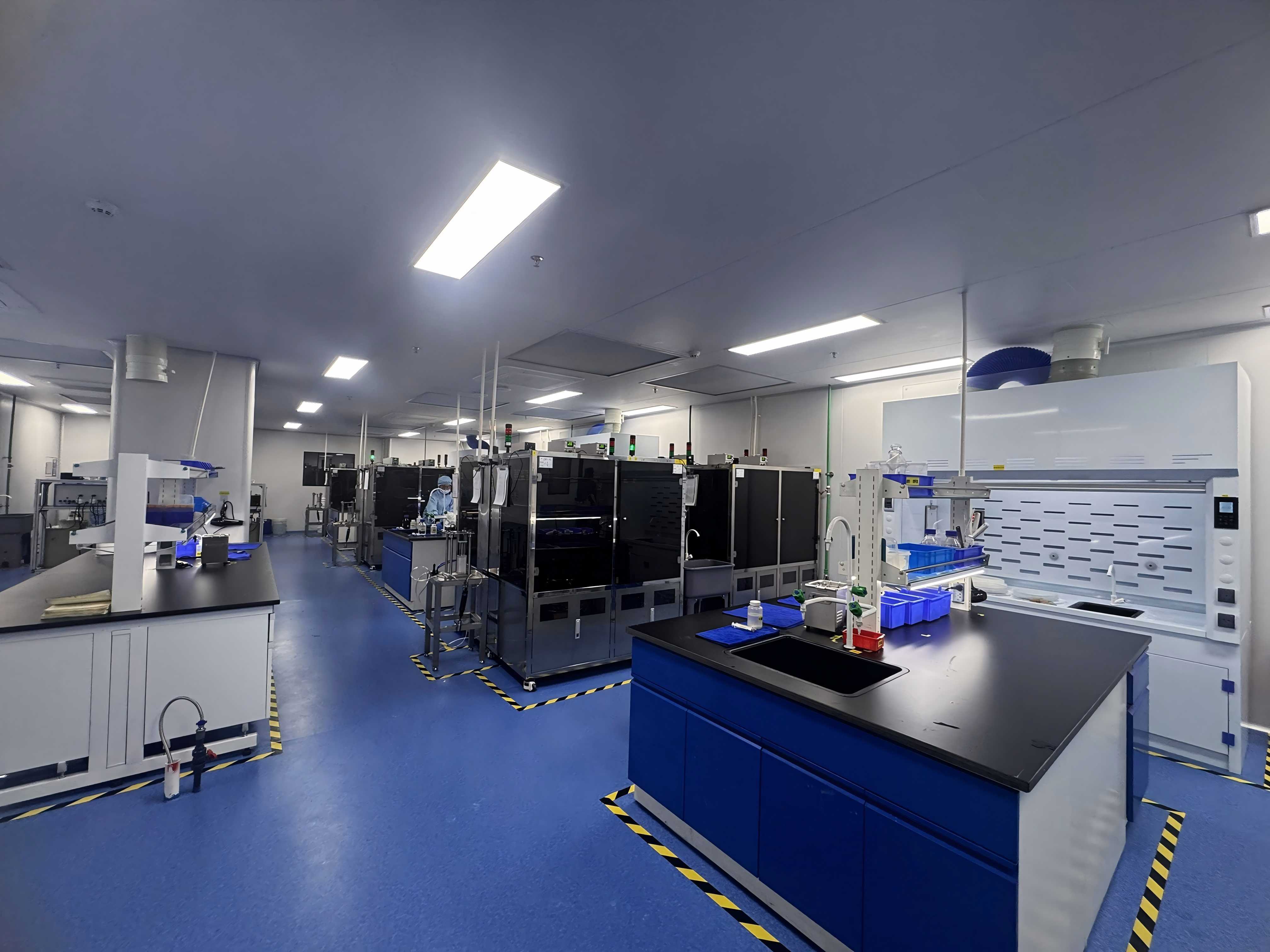
Environmental stability is part of the cutting parameters, not a background detail.
6. Vibration control and permanent cleanroom stability
A dicing saw is a precision instrument that measures its own cut in microns. Anything that changes the relationship between blade and workpiece from one wafer to the next changes the cut: thermal drift, a particle settling on the workpiece, or floor vibration reaching the spindle. Permanent cleanroom stability matters more than a cleanroom certificate for exactly this reason. Temperature and humidity stability keep dimensional behaviour consistent across a shift. Particulate control keeps debris and contamination out of the kerf. Vibration isolation protects the micron-level positioning on which an ultra-thin blade depends. A facility that is stable only during qualification runs will not reproduce qualification results in volume production.
7. Verification closes the loop
None of the physics above produces a repeatable result unless it is measured. Standardised process parameters, batch data tracking and comparative testing of adjacent batches are the mechanism that converts an engineering principle into an outgoing quality guarantee. Without that loop, a thin blade behaves well on the sample and unpredictably in production — which is the most expensive outcome in a dicing line.
Use Cases: Where These Physics Decisions Show Up
- 300 mm semiconductor wafer dicing. Large diameter combined with a thin substrate leaves the least mechanical margin. Hubless, ultra-thin formats and tight runout control are the levers that matter.
- SiC and hard-material dicing. Metal bond blades are used for harder materials such as SiC, where grit retention and kerf stability dominate over gentle cutting behaviour.
- Optical communication and optoelectronic devices. This segment represented 16% of the dicing blade market in 2024, worth USD 69.9 million, driven by 5G infrastructure expansion. Optical device cutting adds surface-quality requirements alongside dimensional accuracy.
- Functional ceramic substrates. Ceramics are brittle, so sub-surface micro-crack control and clean kerf edges matter as much as throughput.
- Precision alloy components. With a more ductile workpiece the balance shifts away from fracture control towards heat management, burr control and dimensional repeatability.
Comparison Table 1: Dry vs. Wet Sawing — How the Physics Changes
| Physical factor | Dry sawing | Wet sawing |
|---|---|---|
| Coolant at the contact zone | None; all friction heat stays in blade and workpiece | Process fluid, commonly deionised water, acts continuously at the cut |
| Dominant heat path | Conduction into blade, workpiece and fixture | Convection carries most heat away with the fluid |
| Debris handling | Relies on airflow, blade rotation and extraction; re-cutting risk is higher | Fluid flushes kerf debris out before it can be re-cut |
| Friction at the interface | Higher, because no lubricating medium is present | Lower, because the fluid reduces friction in the contact zone |
| Main process control burden | Spindle speed, feed rate and blade exposure must be tightly matched | Fluid chemistry, flow and purity must be controlled alongside machine parameters |
| Where it tends to fit | Workpieces where moisture or residue is unacceptable, with tooling and extraction designed for it | Established default for most high-volume semiconductor wafer dicing |
Comparison Table 2: What Recent Market Data Says About Blade Formats
| Blade format | Verified market signal | Decision implication |
|---|---|---|
| Resin bond blades | 42% share of the dicing blade market in 2024 (Dicing Blade Market Report 2026) | The volume default where a gentler cut and earlier grit release suit the workpiece |
| Metal bond blades | 33% share; used for harder materials such as SiC (Dicing Blade Market Report 2026) | Selected where the workpiece is harder or more abrasive and grit retention dominates |
| Hubless blades | Increasingly dominant for 300 mm wafer processing; superior stability and reduced runout on substrates thinner than 50 µm (Semiconductor Equipment Market Data) | The reference format for thin substrates and large wafer diameters |
| Total dicing blade market | USD 1.19 billion in 2024 (Market Research Intel) | Category scale and supply maturity; supplier evidence becomes the differentiator |
FAQ
1. Which standards apply to a diamond sawing blade used in wafer dicing?
Diamond tools, including sawing blades, are categorised under ISO 22180:2019, which distinguishes between CVD diamond-coated and monocrystalline or polycrystalline types. A buyer should therefore confirm that the blade type being quoted is declared against that classification, and that the manufacturer operates a documented quality management system. WINTIME, for example, implements an ISO 9001 quality management system with standard operating procedures, dedicated quality inspectors per production batch, and a batch quality file that can be traced on request.
2. How thin can an ultra-thin wafer sawing blade be, and what does that mean for wafer survival?
A blade thickness below 9 microns has been achieved and mass-produced. WINTIME's "Ultra-thin Wafer D Blade" project reached a blade thickness of less than 9 microns, and the company is one of the few domestic manufacturers able to achieve mass production at that level. For wafer survival, thinness lowers the mechanical load because less material is removed and the kerf is narrower — but only if runout, bond behaviour and heat removal are controlled. On substrates thinner than 50 µm, hubless designs are increasingly dominant for exactly this reason.
3. How should buyers compare cost when blade prices differ?
The relevant unit is not blade price but cost per good die. Four variables drive that number: blade life before replacement, kerf width and the material it consumes, the yield loss caused by chipping or sub-surface damage, and unplanned downtime when a cut fails. A lower-priced blade that increases edge chipping or kerf drift shifts cost into rework, scrap and lost tool time, while a blade that holds its geometry across a full batch reduces all three. Batch-to-batch consistency should be treated as a cost variable, which is why batch data tracking and adjacent-batch comparative testing are part of the commercial case rather than only the quality file.
4. Can a blade be validated before a volume commitment?
Validation normally happens on the customer's own material and saw, because the cutting balance depends on the workpiece, the machine and the environment together. A blade that performs on one substrate can behave differently on another, so the decision-stage questions are always the same: which format and bond suit the material, which parameters the blade is designed to run at, and whether the supplier can reproduce the validated blade in later batches. Teams can direct sample and specification questions to the WINTIME team by email at shenxiangfei@ntwintime.com or by WhatsApp at +8618888053207, and reference the technical brochure linked at the end of this article.
5. What determines lead time and supply continuity for sawing blades?
Lead time and continuity are functions of production capacity, process standardisation and batch traceability. WINTIME operates a 34,000 ㎡ production base in Rugao City with an annual production capacity of more than 1,000,000 dicing blades, staffed by approximately 100 employees including an R&D team of 35 engineers, and exports to Southeast Asia, East Asia, North America and Europe. Automatic production equipment and standardised parameters reduce the variability that forces re-scheduling, while the batch production data tracking system and batch quality files allow a specific run to be traced if a question arises. For teams planning a recurring programme, confirming capacity, batch policy and traceability before the first order is what turns a blade purchase into a supply plan.
Conclusion
Keeping a wafer whole during sawing is a matter of holding three forces in balance at the same time. Mechanical load is set by blade thickness, exposure and bond behaviour. Thermal load is set by friction and by the coolant decision, which is why dry and wet cutting produce genuinely different process physics rather than two versions of the same recipe. Vibration and runout are set by mounting, machine condition and whether the environment around the saw is permanently stable instead of occasionally stable. A supplier's real capability in this category is not measured by how thin a blade can be quoted, but by how consistently that blade repeats — which is why process standardisation, batch data tracking and comparative testing of adjacent batches belong in the same conversation as blade specification.
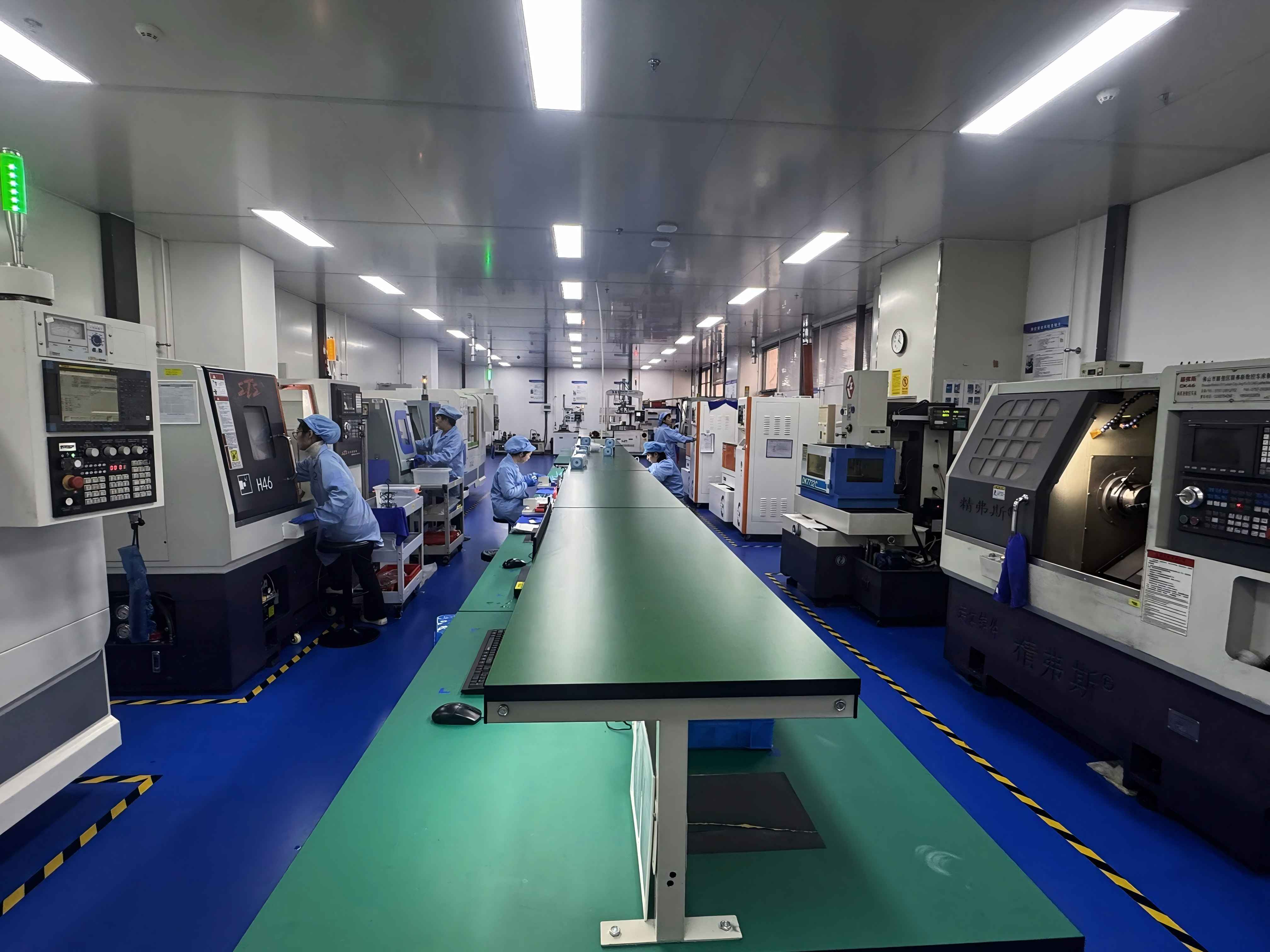
Next step: match the blade to your material and machine
If you are comparing sawing blade formats for a decision-stage programme, the fastest route is a technical review of your workpiece, substrate thickness and saw configuration.
Email: shenxiangfei@ntwintime.com | Tel: +86 13851530812 | WhatsApp: +8618888053207
Website: en.wintime.net.cn | Address: No. 868, Fushou East Road, Rugao City, Jiangsu Province
Have Questions or Need More Details?
Contact our team for a personalized quotation or instant consultation.
Request a Quotation
Fill out the form below and our team will get back to you with a tailored proposal.
WhatsApp Direct Chat
Prefer to chat in real-time? Message us on WhatsApp for instant assistance & quick answers.
- Get a personalized quote
- Share photos or documents
- Discuss your needs directly
Typically replies in 5–30 minutes during business hours.