
Too Many Rejects? Fix Sawing Blade Misalignment and Feed Rate
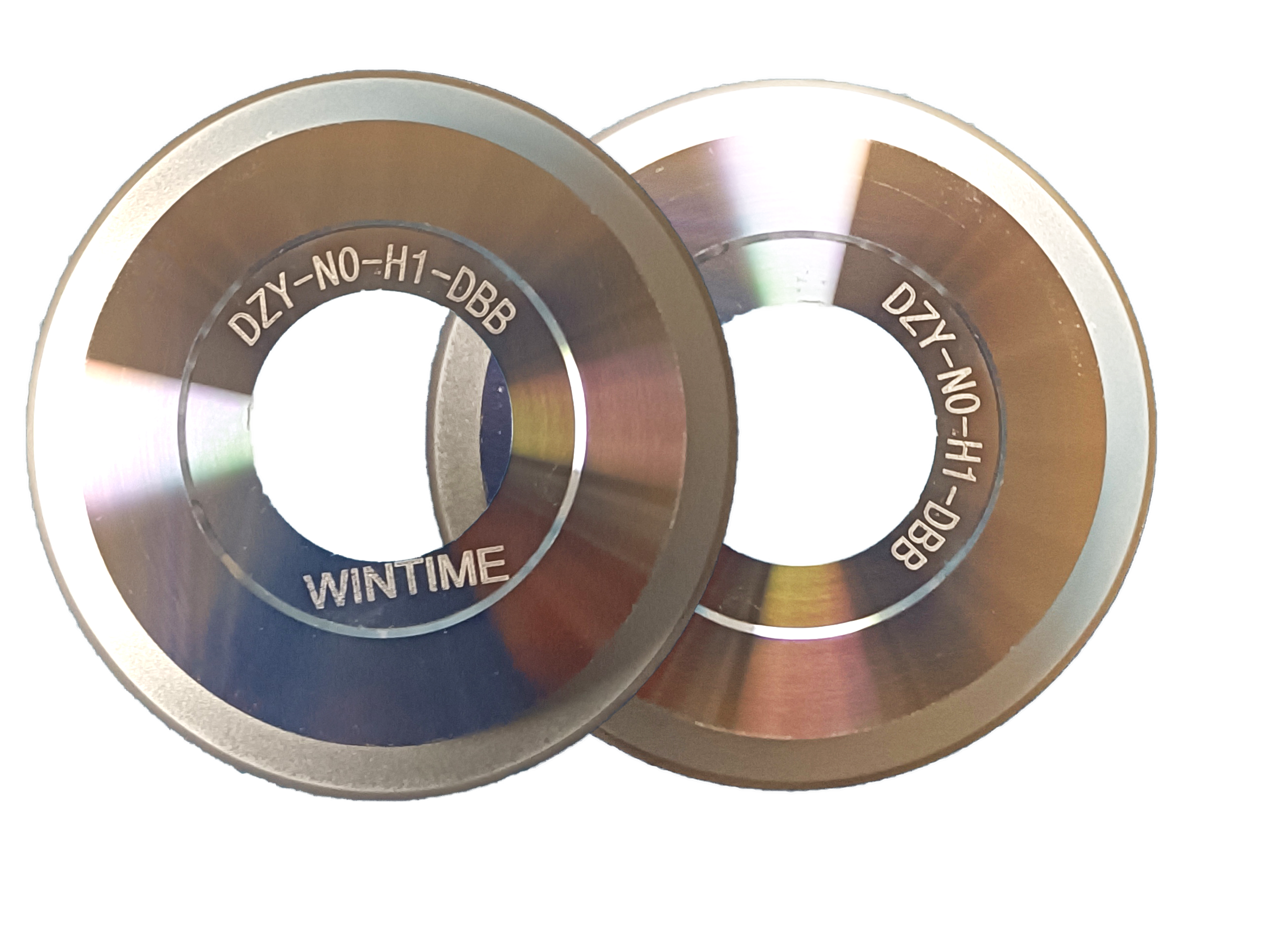
Reject spikes in precision dicing most often come from two correctable conditions rather than a defective blade: blade-to-street misalignment and a feed rate that does not match the blade's thickness and bond. Both are measurable. Checking kerf and thickness against published values — a thickness range of 8μm to 50μm, a cutting accuracy of ±0.002mm and a spindle window of 30,000–60,000rpm — tells a process team within one shift whether the loss is geometry, dynamics or environment.
This guide is written for process engineers, dicing operators and procurement teams who are already evaluating blade specifications and need a decision on what to change. It separates the two error families, identifies which published values to verify first, and provides a correction sequence that lowers reject counts without automatically reordering blades.
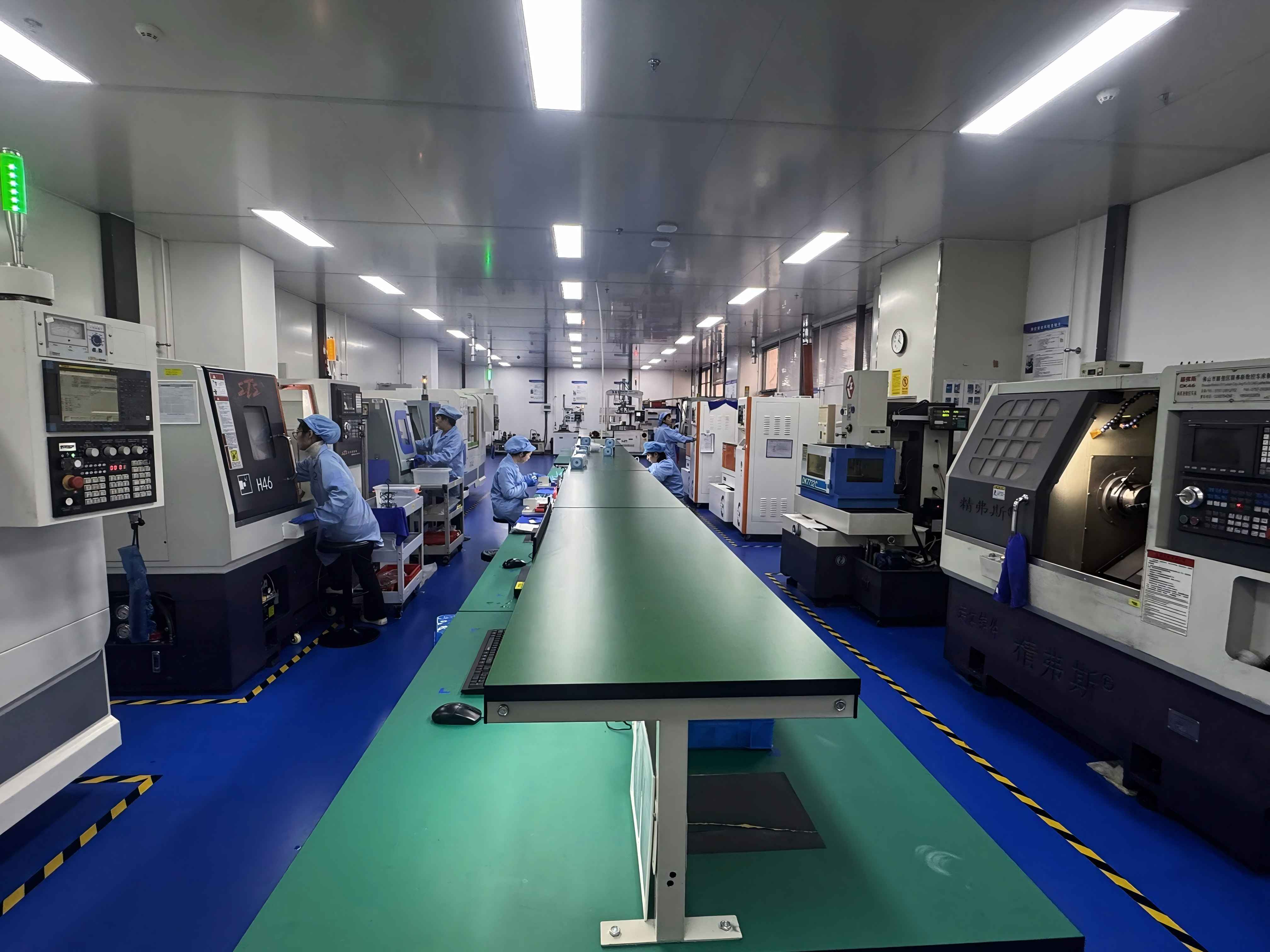
WINTIME Semiconductor Technology Co., Ltd. is a manufacturer of high-precision sawing blades and dicing blades established in 2020 in Rugao City, Jiangsu Province, China. The company runs a 34,000㎡ facility with 100 employees, including a 35-engineer R&D team, and serves customers in Southeast Asia, East Asia, North America and the European Union, with exports representing 30% of its business. Its ultra-thin wafer dicing blade project has reached a blade thickness below 9 microns in process, and the company is one of the few domestic manufacturers able to mass-produce blades at that thickness.
Problem Definition: One Reject Number, Two Error Families
A reject number on its own does not identify a cause. In wafer dicing and precision component cutting, the units lost at the street are usually the combined result of three different failure modes reported as one figure: blade misalignment, feed rate error and process drift. Separating them is the entire correction job.
Misalignment: a static geometry error
Misalignment means the blade is not travelling exactly along the programmed street. Its sources are mechanical and measurable. The blade may not be seated square on its hub or flange. The spindle hole may not match the spindle diameter closely enough. A hubless blade on its arbor may carry contamination that tilts the cutting plane. The workpiece may not be flat on its mounting tape. Blade thickness belongs to this group as well, because a narrow kerf leaves less lateral margin for every one of those errors. What the operator sees is a kerf sitting off-centre, chipping concentrated on one side of the street rather than spread evenly, and die position drifting from target.
Feed rate error: a dynamic removal error
Feed rate error means the blade is being asked to remove more material per unit of time than its bond and thickness allow. Typical sources are a feed value carried over from a thicker blade, a spindle speed that is set correctly but not held across the cut, and step-cut parameters copied from a different material. The result is random chipping across the wafer, micro-cracks below the street, and lateral deflection of the blade.
Process drift: the error that appears late
A third group only surfaces after the machine has been running for hours. Temperature moving outside the working window, humidity shifting the behaviour of mounting tape and static, and ordinary blade wear across a long run all change the cut without changing any setting. Class 100/1000 cleanroom operation at 22±2°C and 45%–55% relative humidity is the reference condition WINTIME specifies for its sawing blades; a line drifting outside that window will generate rejects that no blade specification can correct.
Industry Background: Why Alignment Tolerance Is Now a Production Constraint
The commercial pressure behind this problem is straightforward. The global wafer dicing blade market was valued at USD 1.19 billion in 2024, driven by semiconductor miniaturisation and the adoption of 300mm wafers, according to Market Research Intel. As substrates thin, the lateral margin available to mounting and feed error shrinks faster than the blade itself.
Blade format has already moved in response. Hubless dicing blades are increasingly dominant for 300mm wafer processing because of their superior stability and reduced runout on thinner substrates below 50µm, according to Semiconductor Equipment Market Data. The same shift changes the failure mode: with less hub mass and a thinner cutting rim, seating quality and spindle continuity matter more than they did on conventional hubbed blades.
Bond selection shapes the feed-rate side of the equation. Resin bond blades held a 42% share of the dicing blade market in 2024, while metal bond blades used for harder materials such as SiC accounted for 33%, according to the Dicing Blade Market Report. Resin and metal bonds do not share a feed window, so a program transplanted between them will produce rejects even when the blade itself is within specification.
Application mix adds a second constraint. Optical communication and RF/optoelectronics applications accounted for 16% of dicing blade market share in 2024, equal to USD 69.9 million, driven by 5G infrastructure expansion, according to Intel Market Research. These devices tolerate very little edge damage, which makes a feed error that would pass in a packaging line visible immediately at the street.
Standardisation and supply structure complete the picture. Diamond tools, including sawing blades, are categorised under ISO 22180:2019, which distinguishes between CVD diamond-coated and monocrystalline or polycrystalline types. Leading competitors in high-precision semiconductor dicing blades include DISCO Corporation, Tokyo Seimitsu (Accretech), Advanced Dicing Technologies (ADT) and Asahi Diamond, according to Credence Research. Buyers comparing those suppliers are, in practice, comparing how well each blade geometry can be seated and fed on the buyer's own machine — which is exactly the variable that causes rejects.
The Corrective Framework: Verify Kerf, Dimensions, Spindle Continuity, Then Feed
The correction order matters more than any single setting. Geometry comes first because it is cheap to check and impossible to compensate for later. Feed rate comes second because it can only be set correctly once the geometry is known. Environment comes third because it determines whether the first two hold across a full run.
1. Start with the kerf budget, not the blade brand
The kerf budget is the programmed street width minus blade thickness minus the lateral movement the machine will actually produce. As blade thickness falls toward the ultra-thin range — down to 8µm at the low end of the SB-001 specification, and below 9µm in WINTIME's ultra-thin wafer dicing blade programme — the same absolute runout consumes a larger share of that budget. A mounting error that was invisible at 50µm becomes a reject at 9µm. This is the single most common reason a line reports a sudden reject problem after a thickness change that was itself an improvement.
2. Verify dimensional standards before touching the spindle
Dimensional verification is the fastest way to eliminate the blade as a variable. The published reference values for WINTIME's SB-001 sawing blade are a thickness range of 8µm to 50µm, a cutting accuracy of ±0.002mm, a spindle speed range of 30,000–60,000rpm and a hardness of HRC 65–70. Diameter and spindle hole size are customisable, which means the hole fit on a given machine is a specification decision rather than a fixed constraint.
The verification methods are equally specific: geometric dimension inspection with a vernier calliper and laser diameter gauge, hardness and wear resistance testing on a material testing machine, dynamic balance detection on a high-speed dynamic balance tester, and a cutting performance simulation test against the actual workpiece material. If a shipment has passed those checks and the line still produces a one-sided reject pattern, the cause sits downstream of the blade.
3. Check spindle precision continuity, not just spindle speed
Reaching 30,000–60,000rpm is not the same as holding it. Precision continuity means the spindle speed stays inside its window from the first street to the last, the cutting plane stays square, and runout stays within the tolerance the kerf budget can absorb. Hubless formats help here on thin substrates because reduced runout is one of their defining advantages, but they also remove the stabilising mass of a hub, so arbor cleanliness and seating technique become part of the measurement rather than an afterthought.
4. Recalculate feed rate against chip removal capacity
Feed rate should be derived from removal capacity, not from a previous job. The SB-001 specification publishes a chip removal rate of at least 1.2mm³/s. A feed value that pushes demand above what the bond can evacuate forces the blade to deflect, and deflection reads on the die as misalignment. The practical rule is to reduce feed first and observe whether the one-sided pattern changes; if the pattern is genuinely geometric, feed reduction will not move it, which is itself a useful diagnostic result.
5. Match the bond to the material before adjusting anything else
Bond type sets the removal behaviour the feed rate has to respect. Resin and metal bonds are both available in the WINTIME range, and metal bond is the standard choice for harder materials such as SiC. Setting a resin-bond feed profile onto a metal-bond blade, or the reverse, produces a reject pattern that looks like a machine fault and resists every mechanical adjustment.
6. Hold the environment inside its window
Cleanroom class, temperature and humidity are part of the correction, not background detail. WINTIME specifies Class 100/1000 operation, constant temperature of 22±2°C, constant humidity of 45%–55%, a dust-free and anti-static environment, and high-speed spindle operation. Temperature drift changes the dimensional relationship between spindle, blade and workpiece; humidity drift changes how the mounting tape holds the workpiece flat. Either one produces rejects that reappear after every blade change.
Step-by-Step Breakdown: A Reject Investigation Sequence
The sequence below is ordered by cost and reversibility. Each step produces a record that either clears a variable or identifies it, and no step requires purchasing anything.
- Map the reject pattern by location. Record whether losses cluster on one side of the street, appear randomly across the wafer, or only appear late in the run. One-sided clustering points to geometry; random distribution points to feed and dynamics; late appearance points to drift.
- Measure kerf and blade thickness against the specification. Confirm the blade is inside its stated thickness range and that the measured kerf is consistent with the programmed street width. A kerf that reads wide at the edge and narrow at the centre is a seating signal.
- Inspect hub, flange and arbor seating. Check for contamination, burrs and uneven clamping force. On hubless formats, verify that the arbor face is clean and that the blade sits fully flat before clamping.
- Log spindle speed across the full cut. Confirm the spindle holds its programmed value from the first street to the last rather than merely reaching it at start-up, and confirm runout is inside what the current kerf budget can absorb.
- Recalculate feed rate from removal capacity and material. Compare the programmed feed with the chip removal rate the blade can sustain, then confirm the bond type matches the material being cut. Reduce feed before changing any other dynamic parameter.
- Audit environment logs for the run window. Check temperature against 22±2°C, humidity against 45%–55%, cleanroom class against Class 100/1000, and static control status. A drift event that coincides with the reject start usually closes the investigation.
- Change specification only after the first six steps are cleared. If geometry, feed and environment are all verified and the reject pattern persists, the blade format is the remaining variable — and a trial quantity, not a full order, is the correct next move.
Use Cases: Where Misalignment and Feed Errors Surface First
Semiconductor wafer dicing and scribing
On 300mm wafers with hubless blades, the dominant reject driver is seating and runout rather than blade wear. Because hubless formats reduce runout on substrates below 50µm, they reward careful arbor practice and punish contamination, which makes the seating check the highest-value step in the sequence.
Ultra-thin wafer processing below 9µm
At blade thickness below 9µm, the kerf budget is small enough that feed rate and lateral movement have to be treated as a single combined limit. The typical error is applying a feed profile developed for a thicker blade; the typical correction is a reduced feed combined with a verified seating check before any specification change.
Semiconductor package cutting
Package cutting mixes materials within a single workpiece, so the blade passes through mould compound, metal and dielectric in one street. Feed rate errors here show up as localised chipping at material transitions, which operators frequently report as misalignment because the pattern changes along the cut.
Optical communication device cutting
Optical communication and RF/optoelectronics accounted for 16% of dicing blade market share in 2024, and these devices tolerate very little edge damage. Where the die is optically active, a feed error that would be acceptable in packaging becomes a functional reject, so the feed check moves ahead of any cosmetic assessment.
Functional ceramic and precision alloy cutting
Functional ceramics and precision alloys are harder and more abrasive than silicon, which shifts the balance toward metal bond blades and toward wear continuity across the run. The reject signature is a gradual increase in chipping rather than a step change, and the correction is a feed re-derivation plus a hardness and wear check rather than a seating adjustment.
Comparison Table: Reference Values for a Reject Investigation
The table below lists the parameters that determine whether a reject pattern is geometric, dynamic or environmental, together with the published reference values available in the WINTIME sawing blade specification and the applicable standard.
| Parameter | Reference value | Role in a reject investigation |
|---|---|---|
| Blade thickness | 8µm–50µm; ultra-thin programme below 9µm | Sets the kerf budget; thinner blades leave less lateral margin for seating and runout error |
| Cutting accuracy | ±0.002mm | Defines the lateral tolerance available before misalignment becomes a reject |
| Spindle speed | 30,000–60,000rpm | Speed must be held across the cut, not only reached at start-up |
| Blade hardness | HRC 65–70 | Governs wear continuity and whether chipping increases gradually across a run |
| Bond type | Resin bond or metal bond | Sets the feed window; metal bond is used for harder materials such as SiC |
| Chip removal rate | ≥1.2mm³/s | Upper limit for feed rate before the blade deflects and mimics misalignment |
| Cleanroom class | Class 100/1000 | Particle and static control around the cutting zone |
| Temperature and humidity | 22±2°C / 45%–55% | Dimensional stability of spindle, blade, workpiece and mounting tape |
| Diamond tool standard | ISO 22180:2019 | Classifies diamond tools including sawing blades and distinguishes CVD-coated from monocrystalline or polycrystalline types |
| Blade format | Hubbed or hubless | Hubless formats reduce runout on thin substrates and are increasingly used for 300mm wafers |
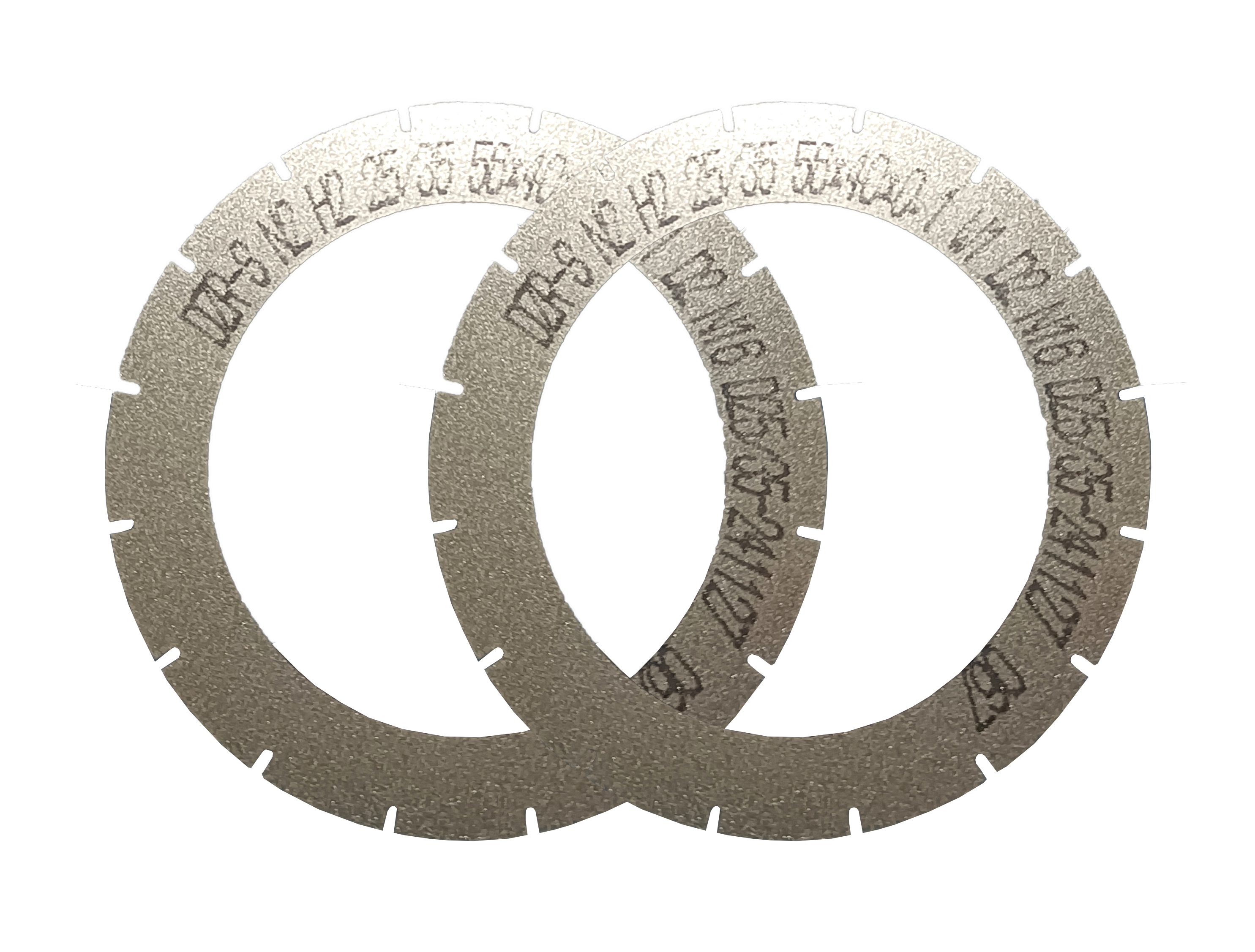
WINTIME's blade range covers hubbed and hubless formats, resin and metal bonds, and the DZY Series wafer sawing blade, DZR Series sawing blade and DZR-S Series slotted sawing blade, all supplied from a facility with a monthly capacity of more than 800,000 pieces for standard specifications and more than 80,000 pieces for customised and special-shaped products.
FAQ: Practical Questions Buyers Ask Before Changing a Blade
Which standard applies to diamond sawing blades, and does it cover the blade types used in dicing?
Diamond tools, including sawing blades, are categorised under ISO 22180:2019, which distinguishes between CVD diamond-coated types and monocrystalline or polycrystalline types. The standard identifies the tool category; it does not replace a supplier datasheet. For dicing, the operating condition matters as much as the category, which is why WINTIME specifies Class 100/1000 cleanroom operation at 22±2°C and 45%–55% relative humidity alongside the blade specification.
Can blade geometry be customised to correct misalignment on a specific dicing machine?
Yes. WINTIME's OEM, ODM and customised production covers blade diameter, thickness and spindle hole size; bond type in resin or metal; diamond abrasive grain size and concentration; anti-rust, heat-dissipation and wear-resistant coatings; cutting performance targets such as cutting speed and service life; export packaging; and special-shaped blades in non-standard sizes. A 35-engineer R&D team supports cutting process matching and equipment adaptation, and quality control includes geometric dimension inspection with a laser diameter gauge and dynamic balance detection on a high-speed dynamic balance tester.
What drives the cost of a misalignment correction, and is a custom blade always the more expensive route?
A custom blade is not automatically the right purchase, and the cheapest correction step is the one that costs nothing: verifying the kerf budget, seating and feed rate first. When a specification change is genuinely required, commercial differences come mainly from order size and lead time. For standard specifications the minimum order quantity is 50 pieces with a lead time of 2–5 working days; for customised products the minimum is 300 pieces with a lead time of 10–25 working days, adjustable for large orders. Long-term cooperative customers can be offered flexible terms on both figures.
Can a blade be validated on the line before committing to volume?
Yes. The 50-piece minimum for standard products and the 300-piece minimum for customised products both allow a trial quantity rather than a full order. Validation is supported by a cutting performance simulation test against the actual workpiece material, technical support for cutting process matching and equipment adaptation, and product application training for new customers.
How quickly can blades be replaced after a reject spike stops the line?
Standard specifications ship in 2–5 working days and customised orders in 10–25 working days, with monthly capacity of more than 800,000 pieces for standard products and more than 80,000 pieces for customised and special-shaped products. Quality problems are investigated with a proposed solution within 48 hours, and long-term supply guarantees with inventory support are available for bulk procurement customers. If the reject pattern has already been narrowed to a seating or feed issue, a sample trial is usually the fastest next step — send the blade specification, machine model and reject pattern to start it.
Conclusion: Correct the Setup Before Replacing the Blade
High reject counts in precision dicing are usually a verification failure rather than a product failure. Misalignment is a static geometry error that appears as a one-sided pattern and is corrected by checking seating, spindle hole fit, runout and the kerf budget. Feed rate error is a dynamic removal error that appears as random chipping and is corrected by deriving feed from the blade's chip removal capacity and matching the bond to the material. Between them sits the environment, which decides whether a corrected setup stays corrected across a full run.
The reference values that make this measurable are already published: a thickness range of 8µm to 50µm with an ultra-thin programme below 9µm, a cutting accuracy of ±0.002mm, a spindle window of 30,000–60,000rpm, a chip removal rate of at least 1.2mm³/s, and a Class 100/1000 environment at 22±2°C. Verifying those six numbers takes less time than a blade change and answers the question that a reject number cannot: whether the loss is geometry, dynamics or drift.
Next Step: Validate the Correction on Your Own Line
If the reject pattern points to alignment or feed rate, a controlled trial is faster and cheaper than a full specification change. Standard sawing blades are supplied from 50 pieces with a 2–5 working day lead time; customised geometry starts at 300 pieces with a 10–25 working day lead time.
Send your blade specification, machine model and reject pattern to shenxiangfei@ntwintime.com, call +86 13851530812, or message WhatsApp at +86 18888053207. Full specifications are available in the WINTIME sawing blade catalogue (PDF).
WINTIME Semiconductor Technology Co., Ltd., No. 868, Fushou East Road, Rugao City, Jiangsu Province, China — en.wintime.net.cn
Have Questions or Need More Details?
Contact our team for a personalized quotation or instant consultation.
Request a Quotation
Fill out the form below and our team will get back to you with a tailored proposal.
WhatsApp Direct Chat
Prefer to chat in real-time? Message us on WhatsApp for instant assistance & quick answers.
- Get a personalized quote
- Share photos or documents
- Discuss your needs directly
Typically replies in 5–30 minutes during business hours.