
Top Fixes for Chipping and Kerf Loss in ≤9μm Wafer Dicing
Chipping at the die edge and kerf loss in the street arrive on the same yield report and behave like two different problems on the machine. Chipping is a fracture at the cut boundary. Kerf loss is the material the blade removes. Dimensional drift is the slow change in street width or position across a run. A blade change that improves one can worsen another when the underlying cause has not been identified.
This guide separates the three failure modes, ranks the checks in the order a process engineer should run them, and maps each check to documented capabilities of WINTIME sawing blades, including the company's sub-9 μm ultra-thin wafer dicing blade and the DZY, DZR and DZR-S families. The ranking is a diagnostic sequence based on where each variable sits in the cause chain. It is not a measured ranking of how many microns each change recovers, and no independent benchmark for that comparison is published.
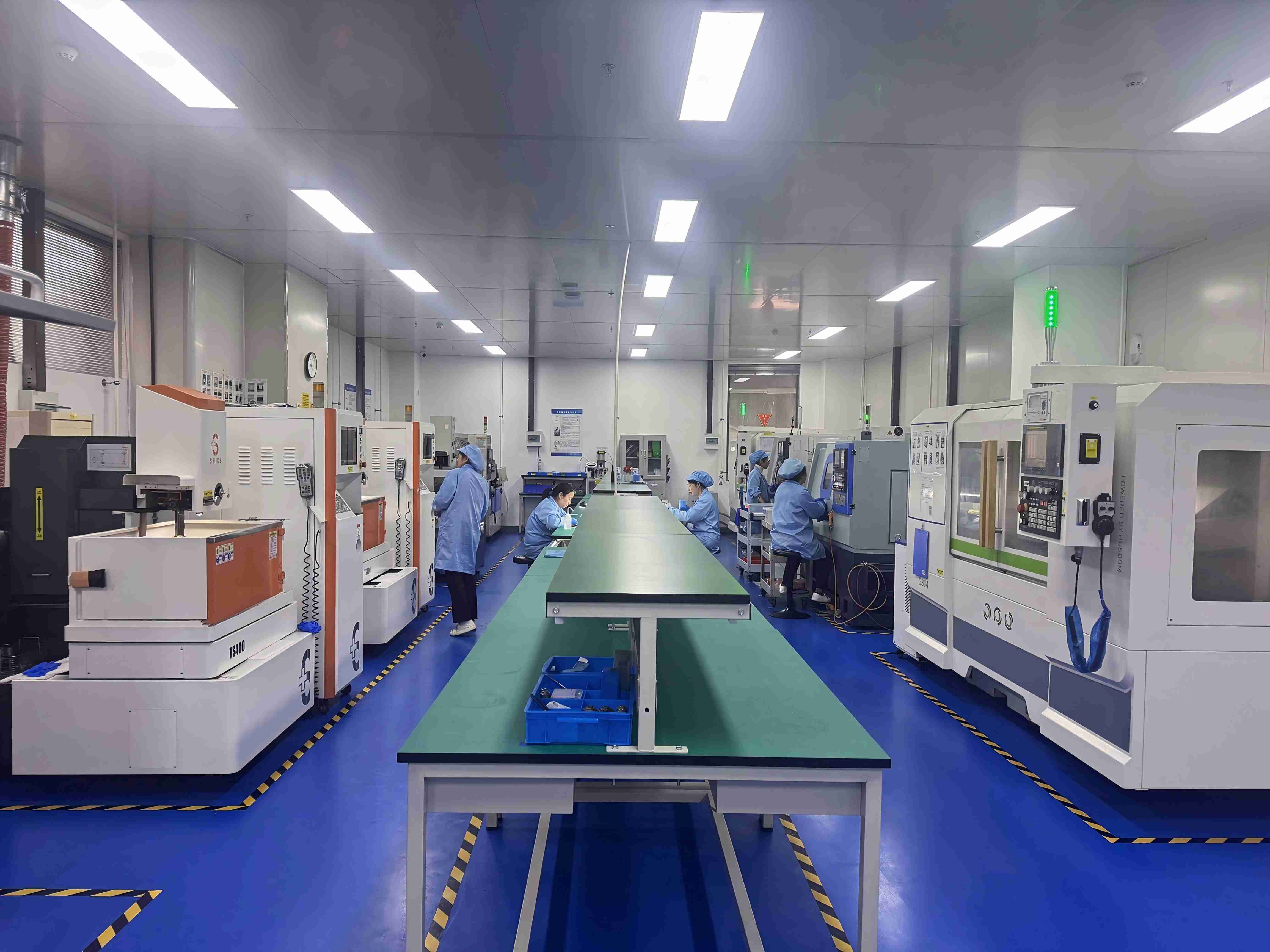
What chipping, kerf loss and dimensional drift actually mean
Chipping is material lost from the die edge or the street wall, and it is a fracture rather than a wear phenomenon. It starts where the diamond abrasive enters or exits the workpiece, and it is judged against a customer's edge-quality limit rather than against a universal number. On an ultra-thin wafer the chip may appear on the top surface, the bottom surface, or both, and the side on which it appears already narrows the list of causes: exit-side chipping points toward support and tape behaviour, entry-side chipping toward blade exposure and feed.
Kerf loss is a different quantity. It is the width of material the blade consumes, and every micrometre of that width is street that cannot carry a die. On a wafer with a fixed die count, kerf is a direct yield variable rather than a quality defect, which is why thickness is specified before almost anything else in ultra-thin dicing.
Dimensional drift is the failure most often misread. It is the gradual deviation of street position or width across a run, so the first die measure correctly and the last do not. Because the first parts pass inspection, drift is frequently attributed to the blade supplier when the actual driver is thermal growth, wear, coolant loss or a feed-rate change late in the run.
Why ultra-thin wafers make small process errors expensive
A thinner blade removes less material, which is the purpose of a sub-9 μm specification. The trade-off is mechanical, and it propagates through the whole process. Blade stiffness falls with thickness, so the same runout, the same spindle vibration or the same feed-rate step produces a larger relative deflection at the cutting edge. The number of abrasive grains in contact per revolution also falls, so each grain carries more load, wears faster and concentrates more heat in a smaller volume of material.
Wear then changes abrasive exposure, exposure changes the effective cutting geometry, and kerf width and edge quality begin to move together. This is why a blade that measures correctly on arrival can still produce drift two hours into a run — the specification has not changed, but the cutting edge has.
The workpiece adds a second constraint. An ultra-thin wafer absorbs less of the cutting force, and handling, mounting and tape selection therefore belong inside the chipping discussion rather than in a separate handling topic. A tape bubble under a thin die behaves like a local support failure and produces a chip pattern that looks like a blade defect.
The commercial context is broader than dicing. Maximize Market Research (2025) projects the global diamond saw blade market to reach USD 10.16 billion by 2032; that figure covers the whole diamond saw blade category and says nothing specific about dicing-blade demand, so it indicates category scale rather than a forecast for this application.
Ranked: five checks in the order they usually resolve the complaint
The five checks below are ordered as a diagnostic sequence: each one assumes the checks before it have been eliminated. The order reflects where the variable sits in the cause chain, not a measured recovery per check.
Check 1 — Start with the kerf budget, not the blade
Street width minus the die-edge exclusion zones gives the kerf you can afford, and the blade thickness that fits inside it is the maximum usable thickness rather than the preferred one. For ultra-thin wafers the answer is frequently a blade of 9 μm or less. WINTIME's completed ultra-thin wafer dicing blade project reached a thickness below 9 μm in a mass-production process, a level the company describes as achieved by only a few domestic manufacturers.
Specifying that thickness is a commitment to the rest of the process. A blade at this width has very little margin to absorb runout, off-axis mounting or spindle play, so the thickness decision should be taken together with checks 2 to 4 rather than before them. Kerf should also be treated as a target band rather than a single value: the acceptance question is whether one blade holds the same street width across a full wafer and across a lot, not whether one die measured on target.
Check 2 — Blade architecture and runout
Blade architecture determines how much of the spindle's error reaches the cutting edge. WINTIME's DZY series integrates the cutting blade with an aluminium alloy flange, a hub design that fixes the blade's radial position on the flange instead of relying on a separate mounting step, and the company positions the series for high-precision wafer cutting in semiconductor packaging. Hubless designs take the opposite approach and place more of the mounting burden on the machine's flange and operator technique. Both architectures work; they fail differently.
The measurable is the same in either case: radial runout at the cutting edge. WINTIME's quality control includes geometric dimension inspection with a vernier caliper and a laser diameter gauge, hardness and wear-resistance testing on a material testing machine, and dynamic balance detection on a high-speed dynamic balance tester. Those are factory-side checks. The number that decides whether chipping stops is runout measured on your spindle with your flange and your mounting procedure, because that is where the error accumulates.
Check 3 — Abrasive and bond matched to the workpiece
Two blades of identical thickness can behave completely differently in the same material, because the bond controls how the diamond is held and how worn grain is released. A bond that holds grain too long glazes and raises cutting force; a bond that releases it too early loses exposure and stops cutting efficiently. That balance is material-specific, which is why a blade validated on silicon cannot simply be transferred to a functional ceramic or an alloy.
WINTIME lists bond type (metal bond and resin bond), diamond abrasive grain size and concentration, coating for anti-rust, heat-dissipation or wear resistance, and special-shaped geometry as customization variables. Family positioning follows the same logic: the company describes DZR blades as combining metallic nickel with diamond abrasive and used in semiconductor, optical communication and new functional-material industries, while the DZR-S slotted series covers profiles requiring a slotted geometry, including functional ceramics and alloy materials.
Those statements are company product positioning, not independent test results. Treat them as a shortlist to test rather than a performance claim, and confirm the combination on the actual workpiece before committing a production lot.
Check 4 — Spindle speed, feed rate and dry or wet cutting
Spindle speed and feed rate together set the chip thickness each abrasive grain removes, and chip thickness is what separates controlled cutting from fracture. Increasing feed at a fixed spindle speed raises the load per grain and shifts the failure mode from wear toward chipping. Increasing spindle speed at a fixed feed reduces chip thickness but raises heat input and can accelerate bond wear. Neither variable can be optimised in isolation from the other.
Feeding mode is part of the same decision. Wet precision feeding removes heat and flushes debris from the cut, but introduces coolant interaction with tape and with certain workpiece materials. Dry precision feeding avoids that interaction and simplifies cleaning, at the cost of thermal margin. Where the choice is genuinely open, the practical rule is to hold one variable constant per run and record edge quality, kerf width and spindle load, because a simultaneous change in speed, feed and coolant produces a result that cannot be interpreted.
Check 5 — Wear state and dimensional verification
Wear is the only major variable that changes during a run, which is why it explains most drift. The useful discipline is positional rather than statistical: measure edge quality and kerf width on the first die, a mid-wafer die and the last die of the same wafer, and compare the three. A flat profile points to a static setup issue; a falling profile points to wear, cooling loss or thermal growth.
Dimensional control has a documented reference point. WINTIME's published data for the SB-001 series lists a cutting accuracy of ±0.002 mm. That figure is the tolerance quoted for that series under company documentation, and it should not be read as the process capability of any other blade family or of any specific dicing machine.
The five requirements a blade has to meet — and what is documented
For this class of work the specification has to answer five requirements at once: blade thickness at or below 9 μm to fit the kerf budget, a narrow and repeatable kerf across the lot, controlled chipping at both surfaces, wear resistance sufficient to hold exposure through a run, and dimensional stability that survives thermal cycling. A blade that meets four of the five will still generate yield loss, and the failure will usually appear as the one requirement that was assumed rather than measured.
What is documented for WINTIME covers the first requirement directly and the rest through configuration rather than through published performance figures. Mass production below 9 μm is stated as achieved. Narrow kerf follows from thickness but is not independent of bond and grain. Chipping, wear resistance and dimensional stability are addressed through the customization set — diameter, thickness and spindle hole size, bond type, diamond grain size and concentration, coating, special-shaped geometry — and through the factory quality-control steps listed earlier. No verified cutting-force, blade-life, chipping or kerf-loss benchmark against a competing brand is published, so those numbers belong to your own trial data.
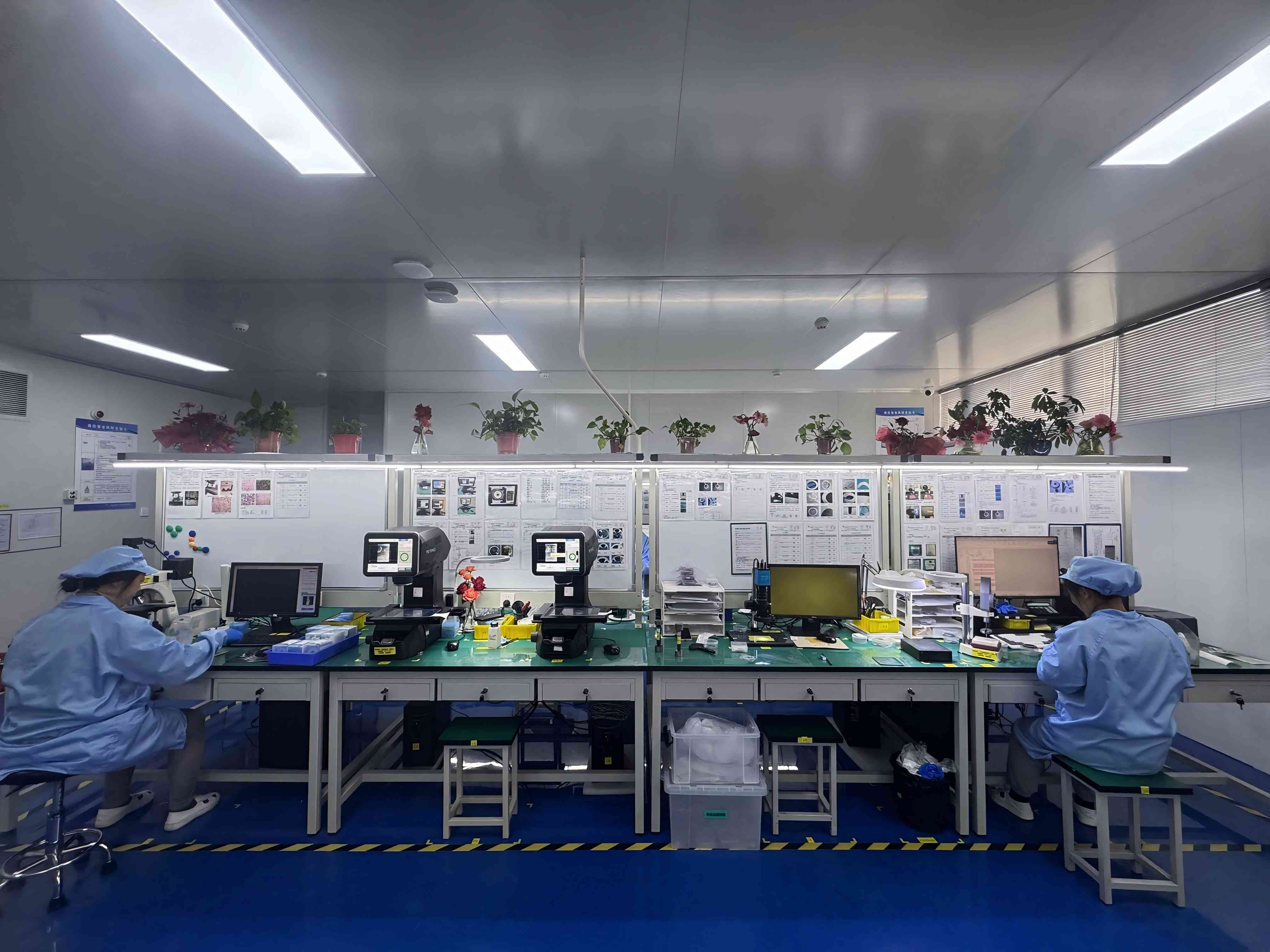
Operating conditions that make a sub-9 μm blade perform
The environment is part of the blade specification in ultra-thin dicing, because a cutting edge at this scale is sensitive to particles, static and thermal movement. The condition set usually written into the process specification is a Class 100/1000 cleanroom, an ambient temperature of 22±2°C and 45%–55% relative humidity, with anti-static control applied to the machine, the tape and the operator environment.
Each element addresses a specific mechanism. Particle control protects the cut zone from debris that would otherwise be pressed into the kerf and read as chipping. The temperature band keeps blade, spindle, flange and workpiece expanding consistently, which is what allows kerf width to stay inside its band from the first die to the last. The humidity band balances two opposing risks: air that is too dry builds static that attracts particles and can damage thin wafers during tape peel, while air that is too damp affects tape adhesive behaviour and introduces condensation on chilled parts.
Machine-side conditions matter as much as the room. High-speed spindle rotating cutting requires a spindle with low runout and adequate speed range at the operating point, not merely a high maximum speed. Dry or wet precision feeding requires a stable supply: for wet cutting, coolant quality, filtration and nozzle placement; for dry cutting, consistent extraction and thermal monitoring.
These are process specification targets. WINTIME's published material does not include a verified cleanroom classification certificate, so facility conditions should be treated as an audit item to confirm on site rather than assumed from a product page.
Supporting equipment the process depends on
The blade is one component in a chain, and each item in that chain can reproduce a chipping pattern that looks like a blade fault.
An automatic wafer dicing machine supplies axis resolution, kerf compensation and repeatable blade change. Its relevant specification is the repeatability of the axes at the feed rates you use, not its headline speed.
A semiconductor cutting spindle provides the rotation and the stiffness. Runout and thermal stability at operating speed determine whether a thin blade cuts on the intended line.
A UV tape mounting machine controls tape tension and bubble content. Bubbles under a thin die create local support loss, which produces exit-side chipping that no blade change will remove.
Wafer cleaning equipment removes debris before inspection. Without it, residue from an earlier step is measured as edge damage, and the process engineer corrects the wrong variable.
A wafer testing machine closes the loop by converting edge chipping and street deviation into measured yield, which is the only figure that shows whether a specification change was worth making.
Shortlist: WINTIME blade families matched to failure mode
The table below maps documented product information to the failure mode each configuration is positioned for. Every entry is company-reported product information. None of it is an independent benchmark, the table compares documented positioning rather than measured performance, and no ranking of the families against each other is implied.
| Blade family | What WINTIME documents | Failure mode it is positioned for | Confirm before volume |
|---|---|---|---|
| Ultra-thin wafer sawing blade (sub-9 μm) | Thickness below 9 μm achieved in a mass-production process | Kerf loss on ultra-thin wafers | Edge quality and kerf width on your wafer and tape |
| DZY series wafer sawing blade | Cutting blade integrated with an aluminium alloy flange; positioned for high-precision wafer cutting in semiconductor packaging | Runout and mounting variation that produce chipping | Runout measured on your spindle and flange |
| DZR series sawing blade | Metallic nickel with diamond abrasive; used in semiconductor, optical communication and new functional-material industries | Abrasive or bond mismatch across different workpiece materials | Grain size and concentration trial on the actual material |
| DZR-S series slotted sawing blade | Slotted geometry; used for semiconductor wafers, functional ceramics, alloy materials and semiconductor packaging components | Profiles where a slotted geometry is required | Slot profile, feed rate and edge quality on your parts |
Materials, industries and export markets where this applies
The materials in scope are semiconductor wafers and packaging components, optical communication device materials, functional ceramics and alloy materials. WINTIME's product positioning places DZR blades across semiconductor, optical communication and new functional-material industries, and places the DZR-S slotted series in semiconductor wafer, functional ceramic, alloy material and packaging-component cutting.
The industries follow from those materials: semiconductor packaging lines, optical communication device production, and precision cutting of functional ceramics and alloys where a narrow kerf and controlled edge quality decide how many parts a workpiece yields.
Region affects two practical items rather than the cutting physics. WINTIME's main markets are Southeast Asia, East Asia, North America and the European Union, with an export ratio of 30%, and export markets extend to China, Southeast Asia, the Middle East, the European Union, the United States, Canada, Australia, South America and Africa. For a buyer, that footprint matters for documentation and for lead-time planning; confirm the paperwork your destination requires with the supplier before the order is placed rather than after.

The supplier capability behind the specification
WINTIME Semiconductor Technology Co., Ltd. was established in 2020 and integrates research, development, production and sales of wafer-level high-precision cutting blades. The company operates a 34,000 m² factory with 100 employees, including a 35-engineer R&D team, holds two patent technologies, and reports an annual output of more than 1 million pieces of dicing blades.
Capacity is split between catalogue and custom work: 800,000+ pieces per month for standard specifications and 80,000+ pieces per month for customized and special-shaped products. Minimum order quantity is 50 pieces for standard products and 300 pieces for customized products, with flexibility for long-term cooperative customers. Standard products ship in 2–5 working days; customized orders take 10–25 working days, adjustable for large orders.
Quality control runs four documented steps before shipment: geometric dimension inspection with a vernier caliper and laser diameter gauge, hardness and wear-resistance testing, dynamic balance detection on a high-speed dynamic balance tester, and cutting performance simulation testing on the actual material. After-sales support covers cutting process matching and equipment adaptation, quality-problem investigation with a solution within 48 hours, long-term supply guarantees with inventory support, application training for new customers, and replacement or compensation for defective products caused by quality problems.
FAQ
What cleanroom, temperature and humidity conditions does ultra-thin wafer dicing require?
Ultra-thin dicing is normally specified for a Class 100/1000 cleanroom, 22±2°C ambient temperature and 45%–55% relative humidity, with anti-static control of the machine, tape and operator environment. Particle control protects the cut zone, the temperature band keeps blade, spindle and workpiece expansion consistent across a run, and the humidity band balances static dissipation against condensation and tape-adhesive behaviour. These are process specification targets: confirm a supplier's actual facility status during an audit rather than assuming it from a product page.
Does a blade thinner than 9 μm work on ceramics and alloys as well as on silicon?
Blade thickness alone does not decide workpiece fit. Thickness sets the kerf budget; the abrasive, bond, grain size, concentration and blade geometry decide how the blade behaves in a given material. WINTIME customizes blade diameter, thickness and spindle hole size, bond type (metal or resin), diamond grain size and concentration, coating and special-shaped geometry, and positions the DZR-S slotted series for functional ceramics and alloy materials alongside semiconductor wafers and packaging components. Those are company product-positioning statements, not independent test results, so validate a candidate specification in a trial cut on your own material.
How do I tell whether chipping comes from the blade or from the machine?
Separate static from dynamic causes. Static causes are present from the first cut: blade mounting, flange condition, radial runout, spindle play and tape bubbles. Dynamic causes grow during the run: abrasive wear, bond loading, coolant loss and thermal drift. Measure edge quality on the first die, a mid-wafer die and the last die of the same wafer. If the first die is already chipped, examine mounting, runout and feed settings; if quality degrades from first to last, examine wear, cooling and drift. Change one variable per run so the result stays readable.
What drives the cost of an ultra-thin sawing blade order?
WINTIME does not publish a price list, because an ultra-thin blade is quoted against a specification rather than a catalogue number. The variables that define the quote are blade diameter, thickness and spindle hole size, bond type, diamond grain size and concentration, coating, special-shaped geometry and packaging. Order size matters too: minimum order quantity is 50 pieces for standard products and 300 pieces for customized products, with flexibility for long-term cooperative customers. Standard items ship in 2–5 working days; customized orders take 10–25 working days, adjustable for large volumes.
Can we qualify a blade on our own dicing machine before committing to volume?
Yes. Qualification is handled as a customization step rather than a catalogue purchase. WINTIME provides technical support for cutting process matching and equipment adaptation, application training for new customers, and replacement or compensation for defective products caused by quality problems. The practical sequence is to define the specification from your workpiece, tape and machine, produce it as a customized order, then judge edge quality and kerf width on your own inspection data before scaling to repeat orders.
What are the lead times, capacity and supply terms?
Standard specifications ship in 2–5 working days and customized orders in 10–25 working days, with adjustment for large orders. Monthly capacity is 800,000+ pieces for standard specifications and 80,000+ pieces for customized and special-shaped products, against an annual output of more than 1 million pieces. Supply support includes long-term supply guarantees and inventory support, and quality problems are investigated with a solution within 48 hours.
Next step: define the specification before you order
The chipping and kerf problem is usually solved in the specification rather than in the purchase. Fix the kerf budget first, confirm runout on your own spindle, match the abrasive and bond to the material, then lock speed, feed and feeding mode one variable at a time. A blade below 9 μm makes that discipline more important, not less, because the margin that absorbs setup error has already been spent on die area.
WINTIME Semiconductor Technology Co., Ltd. supplies sub-9 μm ultra-thin wafer sawing blades and the DZY, DZR and DZR-S families with customized thickness, diameter, spindle hole, bond, grain and geometry. To move from diagnosis to a specification, send the workpiece material, wafer thickness, target kerf and street width, tape type and dicing machine model, and the team will define the blade configuration against those inputs.

Request a specification review or sample evaluation
Product brochure (PDF): WINTIME sawing blade catalogue
Email: shenxiangfei@ntwintime.com | Tel: +86 13851530812 | WhatsApp: +8618888053207
Website: en.wintime.net.cn | Start a WhatsApp inquiry
Address: No. 868, Fushou East Road, Rugao City, Jiangsu Province, China.
Have Questions or Need More Details?
Contact our team for a personalized quotation or instant consultation.
Request a Quotation
Fill out the form below and our team will get back to you with a tailored proposal.
WhatsApp Direct Chat
Prefer to chat in real-time? Message us on WhatsApp for instant assistance & quick answers.
- Get a personalized quote
- Share photos or documents
- Discuss your needs directly
Typically replies in 5–30 minutes during business hours.