
3D Scanner QC: Full-Field vs. CMM vs. Caliper
3D Scanner QC: Full-Field vs. CMM vs. Caliper
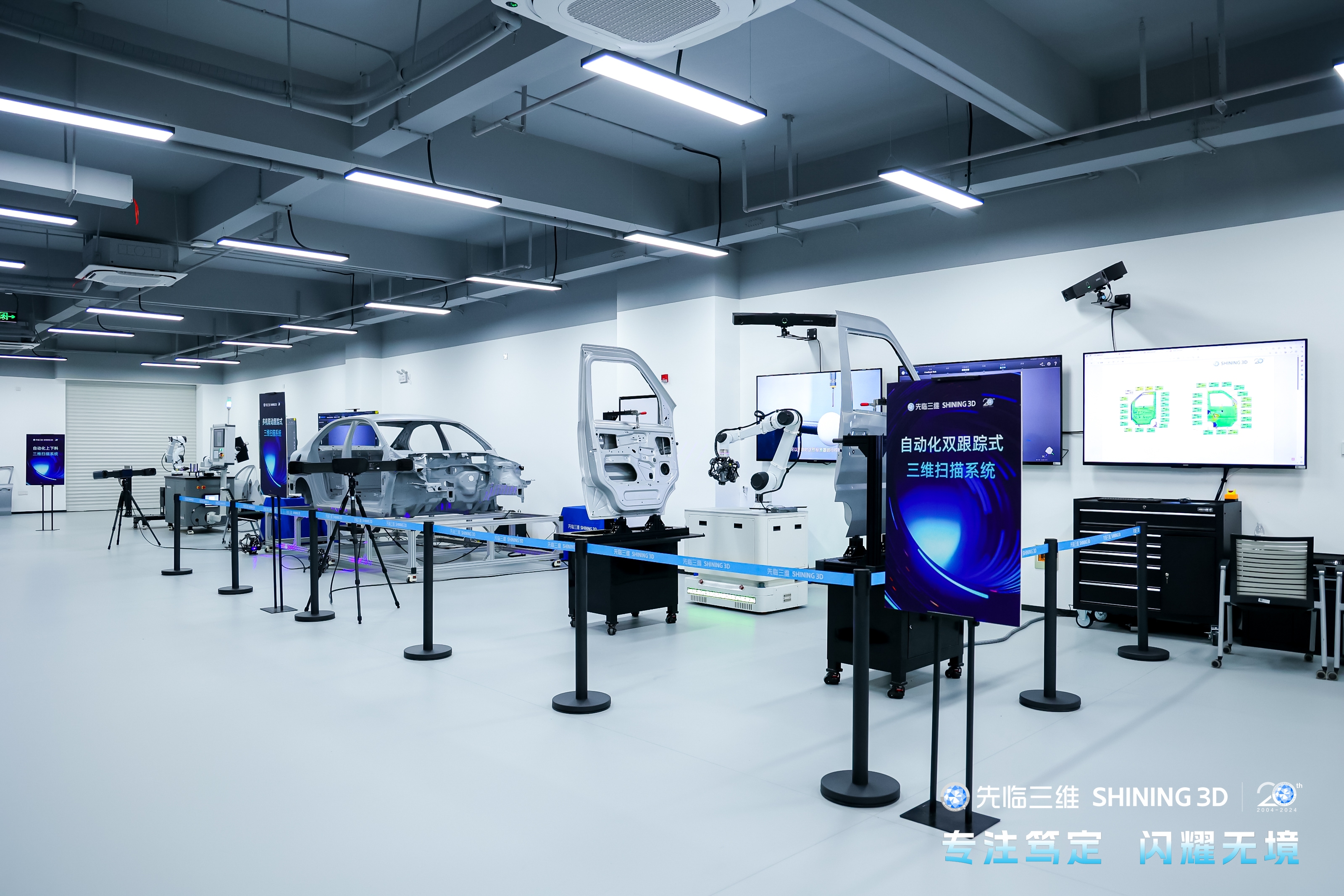
Choosing a 3D scanner for quality control is not a simple choice between a newer device and a traditional instrument. The decision is about what must be measured, where inspection takes place, and whether the task calls for a few defined dimensions or a fuller record of a part’s geometry. For automated in-line inspection, a full-field 3D scanner can capture surface data for comparison and deviation analysis; a coordinate measuring machine (CMM) can serve precision measurement workflows focused on selected features; and a caliper can efficiently check basic dimensions. These tools answer different questions, so a production process may use them for different inspection tasks rather than treating them as interchangeable.
For buyers moving from evaluation to implementation, the practical question is: which measurement approach fits the part, tolerance, inspection location, and production workflow? This framework compares full-field scanning, CMM measurement, and caliper checks on those dimensions. It also explains what must be verified before a scanner becomes part of an automated line. SHINING 3D’s approved materials describe 3D scanning and inspection workflows, as well as the RobotScan Series automation solution; they do not establish that every scanner, robot, software package, or line integration is interchangeable or automatically suitable for every factory.
Start with the inspection question, not the instrument
A caliper is suited to a basic dimensional check when the feature can be reached and the inspection question concerns a specific distance, such as a diameter. A CMM is a candidate when the requirement centers on selected geometric features and a stationary, controlled measurement workflow. A 3D scanner is relevant when the task needs data across a surface, complex geometry, or a comparison between a captured part and its CAD reference. This distinction is especially useful for 3D scanner for automated in-line inspection projects: broad surface coverage may support more extensive analysis, but it does not by itself prove that a scan meets a required tolerance or a production cycle time.
“Full-field” describes the coverage approach: the scanner captures a dense set of surface points rather than measuring only a few discrete locations. In the supplied comparison material, a scan is described as capturing millions of points, while a caliper measures point-to-point dimensions. The additional data can support surface deviation visualization and CAD comparison. The value depends on whether the inspection plan will use that information. If the acceptance decision depends only on one accessible dimension, extensive surface data may not be needed. If the part has curved, freeform, or otherwise complex surfaces, a few isolated measurements may not describe the geometry the quality team needs to assess.
Full-field 3D scanning versus CMM versus caliper
| Decision dimension | Full-field 3D scanner | CMM | Caliper |
|---|---|---|---|
| Measurement coverage | Captures surface geometry as dense 3D data for inspection and comparison. | Measures selected points or geometric features using a probing workflow. | Checks specific accessible dimensions, such as a basic distance or diameter. |
| Useful fit | Complex surfaces, larger parts, deviation inspection, and shop-floor quality control, subject to the system and workflow. | Critical geometric features and stationary workflows where high measurement precision is required. | Quick checks of simple geometry and individual dimensions. |
| Automation role | Can be integrated into an automation solution; the complete inspection cycle and interfaces need verification. | May fit a defined measurement process, but the supplied materials do not specify a particular automated CMM configuration. | A manual instrument in this comparison; do not assume it performs automated full-surface inspection. |
| Important boundary | Results depend on the specified scanner, calibration, alignment, surface, and inspection method. | The supplied buyer material describes CMMs as suited to controlled, stationary workflows; confirm the actual machine and environment. | A few dimensions do not provide a comprehensive 3D surface profile. |
The table is a task-level comparison, not a claim that one method is universally more accurate or less costly. The available materials do not provide matched test results for a particular scanner, CMM, and caliper measuring the same part under the same conditions. Buyers should therefore distinguish the measurement principle from demonstrated performance. Where an acceptance decision requires traceable evidence, request the applicable specifications, calibration or accuracy documentation, and validation results for the proposed setup.
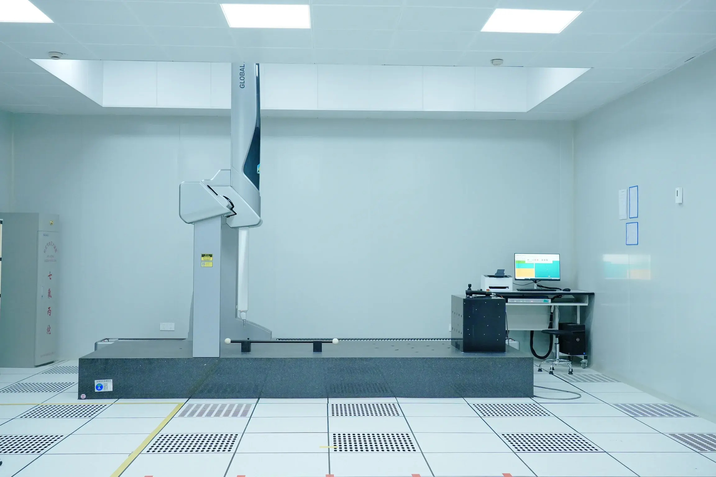
When a 3D scanner changes the inspection decision
A full-field method becomes relevant when the inspection question is broader than “Does this one dimension meet its limit?” Scanned data can be aligned with a CAD reference, analyzed for dimensional deviations, and displayed using 3D color maps. An inspection workflow can also include data processing, alignment, dimensional or GD&T evaluation, and report generation. For a quality team, this makes the scan useful when surface differences across a part need to be reviewed together. It does not mean that every point is automatically an acceptance characteristic: the inspection plan still needs to define the features, tolerances, alignment method, and decision rules that matter.
For first article inspection, the relevant question is whether the planned scan and analysis cover the characteristics required for that first article. For a mold inspection, full-surface data may help compare a complex shape with its reference and examine deviation or wear-related changes; the supplied material describes mold inspection use across design validation, machining analysis, first article and series inspection, and maintenance decision-making. For sheet metal or automotive parts, a team may need to assess broader shape, warpage, or assembly-related geometry. These are application considerations, not evidence that a named system has been validated for every part or production line in those industries.
A 3D scanner for GD&T must be evaluated against the actual geometric characteristics and tolerances that the inspection software and measurement workflow will assess. “Supports GD&T analysis” is not enough on its own to establish acceptance capability. The buyer should identify the required characteristics, the reference datum strategy, how the part is fixtured or aligned, and how the results will be documented. For small precision parts, the supplied selection guidance points to fine-detail capture and resolution as relevant considerations; for medium-to-large objects, it emphasizes measurement volume and volumetric accuracy. The suitable configuration depends on the part and tolerance rather than the keyword alone.
What changes when inspection moves in-line?
Automated in-line inspection adds production and integration requirements to the measurement question. The scanner is only one part of the process. The buyer must consider how the part is presented, how the sensor or robot reaches the necessary surfaces, how data is aligned and analyzed, and how the result reaches the operator or production system. The full inspection cycle includes more than data acquisition: robotic motion, capture, alignment, analysis, and report generation may all affect whether the process fits the intended production rhythm. A fast capture step does not establish a fast total cycle.
The buyer material for inline inspection identifies optical technology and light source, part size and measurement volume, accuracy and metrology certification, cycle time and automation integration, environmental conditions, and software and production interfaces as selection factors. These should be treated as questions to resolve for the actual deployment. For example, the supplied material describes blue laser scanning as a possible fit for complex, shiny, reflective, or dark surfaces, and blue structured light as a possible fit for fine-detail inspection of small precision components. Those descriptions are starting points, not substitutes for testing the actual material, geometry, surface condition, ambient light, and required tolerance in the intended setup.
Automation planning should also define how the inspection result will be used. Is it a digital record for engineering review, an operator-facing deviation map, a report for quality documentation, or an input to a pass/fail decision? The desired output affects software configuration, communication interfaces, and validation. The supplied inline guidance names PLC, MES, and robotic-controller integration as considerations and gives protocols such as OPC UA and Profinet as examples of interfaces to verify. It does not confirm that every SHINING 3D system supports every listed protocol. Confirm compatibility and responsibility for the complete interface with the relevant system suppliers before deployment.
For automated inspection, repeatability of the complete process matters alongside the scanner’s published measurement performance. A buyer should establish how the part is located, how references are maintained, which surfaces are visible, and what happens when a scan is incomplete or a result falls outside limits. Environmental conditions such as vibration, temperature variation, dust, and changing ambient light are specifically identified in the supplied inline selection material as factors to assess. A real acceptance plan should test representative parts in the intended environment; generic product descriptions cannot establish line-level performance.
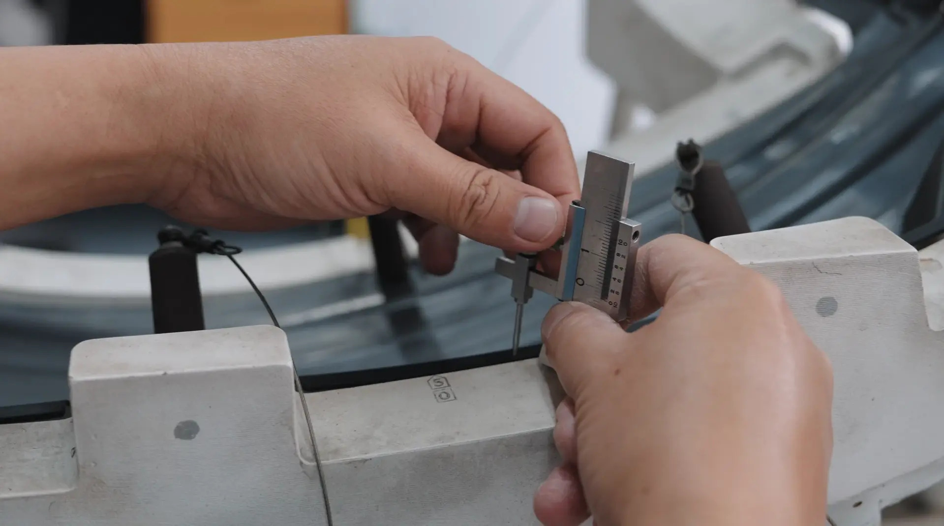
How SHINING 3D describes its automation scope
SHINING 3D is a 3D vision technology company whose approved company information describes work in high-precision 3D vision hardware and software, including industrial 3D scanning and quality-control applications. Its supplied materials describe RobotScan as an automation solution that integrates 3D scanning technologies with a robot arm, controller base, and turntable for batch inspection, in-line measurement, quality control, and digital traceability. This provides a relevant starting point for evaluating an automated inspection concept. It does not establish a specific production-line configuration, achieved cycle time, interface list, or result for a buyer’s part.
That distinction matters in procurement. A system described for in-line measurement is not automatically a complete factory integration. The project specification should state which scanner configuration is proposed, what automation hardware is included, what inspection software and reporting functions are included, and which interfaces must connect to existing equipment. Confirm which tasks are supplied by each party, who validates the measurement process, and what records are delivered at acceptance. If the inspection involves a specific part family or multiple part sizes, document each relevant configuration instead of assuming a single setup covers all cases.
For a candidate scanner, also establish how measurement accuracy is stated and verified over the required measurement volume. The supplied material distinguishes accuracy, repeatability, resolution, and volumetric accuracy; these terms answer different questions. Resolution concerns the smallest detail that can be distinguished, while accuracy concerns closeness to the true dimension and repeatability concerns consistency under unchanged conditions. Greater resolution alone does not prove greater accuracy. For larger objects, volumetric accuracy is relevant because measurement performance must be considered across the measurement volume, not only at a local feature.
A practical buyer decision framework
Define the decision to be made. List the dimensions or geometric characteristics that control acceptance. If the requirement is a small number of accessible basic dimensions, a caliper may be sufficient for that check. If selected high-precision features are central, assess a CMM workflow. If surface coverage, complex geometry, or CAD-based deviation analysis is needed, assess full-field scanning.
Describe the part and its inspection conditions. Record part size, shape, surface, accessibility, required measurement volume, and whether the part can be moved to a controlled area. For a shopfloor inspection workflow, assess the actual operating environment rather than assuming laboratory conditions.
Translate tolerances into evidence requirements. Identify the applicable tolerance range and characteristics, then request documentation relevant to the proposed configuration. Where applicable, the supplied guidance identifies ISO 10360 and VDI/VDE 2634 as metrology standards to check. Verify the certificate scope and test configuration; a standard name alone does not demonstrate that a particular inspection task is covered.
Map the entire automated cycle. Include part presentation, robot motion, data capture, alignment, analysis, reporting, and any response to a failed or incomplete inspection. Compare the total cycle with the production requirement using a representative part and agreed conditions.
Specify the software and interface boundary. Confirm the required output, report format, data transfer, and connection to any PLC, robot controller, or MES. Check who supplies, configures, and validates each connection. Do not infer protocol support from a general description of automation.
Set acceptance criteria before installation. Define representative parts, measurement characteristics, conditions, reporting expectations, and the responsibilities for delivery inspection and post-installation acceptance. The supplied purchasing information lists both delivery inspection and post-installation acceptance as possible acceptance stages; the buyer should define the applicable criteria in the project agreement.
This sequence avoids a common decision error: selecting a sensor from a single headline specification before confirming how the inspection result will be produced and used. It also keeps the comparison fair. The same part, characteristics, tolerance, and operating conditions should inform any evaluation of scanning, CMM measurement, and manual checks. If the methods address different characteristics, explain that difference instead of presenting them as equivalent alternatives.
Fit boundaries and what the comparison cannot establish
Full-field 3D scanning is not a universal replacement for CMMs or calipers. A caliper remains a direct option for simple dimensional checks. A CMM may fit a stationary workflow focused on critical geometric features and high measurement precision. A scanner is relevant when broader surface information or inspection away from a dedicated measurement setup is important, but it must still meet the required accuracy, traceability, and process criteria. The supplied buyer guidance also notes that scanning highly reflective, glossy, or translucent surfaces may require a thin layer of scanning spray in some cases. Surface preparation and any effect on the inspection method should therefore be considered for the actual part.
Likewise, a scanner’s point cloud or mesh is not automatically a finished quality decision. The result depends on acquisition, data processing, alignment, feature definition, and analysis. The inspection software must support the required comparison and reporting, and the process must be validated for its intended use. When a feature is hidden, inaccessible, or dependent on a probing strategy, a scanning workflow may not answer the same question as a contact measurement. In those cases, the team should assess whether methods are complementary and define which result governs acceptance.
The evidence available for this framework supports a method-level comparison and identifies automation-selection factors; it does not provide a controlled performance trial across the three measurement methods. Accordingly, no universal speed advantage, cost saving, or accuracy ranking is asserted here. For an implementation decision, request configuration-specific evidence and evaluate the complete inspection workflow on the intended parts. That is the point at which a general 3D scanner for quality control becomes a substantiated choice for a particular automated line.
FAQ
When is a 3D scanner more useful than a caliper for quality control?
A 3D scanner is more relevant when inspection requires dense surface data, complex geometry assessment, or comparison with a CAD reference. A caliper is suited to checking specific accessible dimensions. If the acceptance question concerns only a basic dimension, full-field capture may add data that the task does not require.
Should a 3D scanner replace a CMM in an automated inspection process?
Not by default. The supplied comparison describes CMMs as suitable for critical geometric features and stationary, controlled workflows, while full-field scanning captures broader surface data and can be considered for shopfloor or in-line inspection. Compare the required characteristics, measurement evidence, environment, and integration needs before deciding whether scanning replaces or complements a CMM task.
What should buyers verify before choosing a 3D scanner for automated in-line inspection?
Verify the part and measurement volume, required tolerance and applicable accuracy evidence, surface and environmental conditions, total inspection cycle, robot and part presentation, software outputs, and required production interfaces. Confirm each interface and responsibility with the relevant suppliers; do not assume a protocol or performance result from a general automation description.
Can a full-field scan directly determine whether a part passes?
A scan provides 3D data, but a pass/fail decision also depends on the defined characteristics, tolerances, alignment, analysis method, and acceptance rules. The inspection process must be configured and validated for the intended part and decision. A dense point cloud by itself is not a complete acceptance criterion.
Company information: SHINING 3D.
Have Questions or Need More Details?
Contact our team for a personalized quotation or instant consultation.
Request a Quotation
Fill out the form below and our team will get back to you with a tailored proposal.
WhatsApp Direct Chat
Prefer to chat in real-time? Message us on WhatsApp for instant assistance & quick answers.
- Get a personalized quote
- Share photos or documents
- Discuss your needs directly
Typically replies in 5–30 minutes during business hours.