
3D Scanner for Quality Control: RobotScan Supplier Evidence
3D Scanner for Quality Control: RobotScan Supplier Evidence

A 3D scanner for quality control is only as dependable as the evidence its supplier can place in front of a quality manager, an auditor, or a customer's supplier-approval team. In an automated inspection cell built on the SHINING 3D RobotScan Series, that evidence has to answer four core questions at once: whether the supplier can issue a traceable accuracy certificate for the exact configuration, whether it can demonstrate a defined metrology software chain, whether it can document industrial-grade reliability in a production environment, and whether it can sustain calibration and technical support after the cell is commissioned.
This article sets out a practical verification method for those layers, using RobotScan Series as the grounded product example. It also examines where documented calibration and support change the arithmetic of inspection work — specifically the manual re-scanning and re-measurement load that builds up when measurement data cannot be signed off the first time.
SHINING 3D (Shining 3D Tech Co., Ltd.) is a 3D vision technology company founded in 2004 and headquartered in Hangzhou, China, with subsidiaries in Stuttgart, Barcelona, California, Florida and Tokyo. Its portfolio covers metrology 3D scanners, professional and entry-level 3D scanners, and dental 3D solutions; the company reports 2025 operating revenue above US$220 million and a headquarters facility of nearly 140,000 m².
Why an Automated QC Cell Raises the Evidence Bar
In a manual inspection station, an operator usually notices when something is wrong with a scan. In an automated cell, the same misalignment, drifted calibration or outdated reference model is applied to every part in the batch — and it repeats until someone audits the data rather than the part. That difference is the core reason supplier evidence matters more for a RobotScan-class deployment than for a standalone handheld purchase.
SHINING 3D describes RobotScan Series as an automation solution that integrates 3D scanning technologies with a robot arm, a controller base and a turntable, delivering end-to-end automated workflows for batch inspection, in-line measurement, quality control and digital traceability. That is a capability description, not a guarantee of measurement performance at a specific plant. Cell performance depends on which scanner head is fitted, how the robot presents the part, how the part is held, and what acceptance test the buyer and supplier agreed before the purchase order.
The opportunity is the same fact seen from the other side. Automation is what allows a plant to move from sampling toward fuller inspection, and digital traceability is what turns inspection records into evidence for customers and auditors. Neither benefit survives if the underlying measurement cannot be traced to a certificate and re-verified on a schedule.
Five Evidence Layers to Request Before Sign-Off
Supplier capability evidence is easier to audit when it is separated into layers, because each layer fails in a different way. The table below is a request template rather than a ranking of suppliers; the documents behind each row are what a procurement team should collect before commissioning.
| Evidence layer | What to request | Failure mode if left unverified |
|---|---|---|
| Certificate and traceability | Calibration or accuracy certificate to ISO 10360 and/or VDI/VDE 2634, with the issuing laboratory's ISO/IEC 17025 accreditation scope | Stated accuracy cannot be traced to a recognised test, and quality sign-off is challenged during an audit |
| Configuration and scope | Written statement of which scanner head, measuring volume and standard artefact the certificate covers, and whether the test is acceptance or reverification | A certificate issued for one head is assumed to cover a different head or a larger measuring volume |
| Software integration | Demonstrated scan-to-report workflow, supported inspection platforms, export formats, and interface to PLC or MES where required | Data arrives in a format the quality system cannot audit, or reports cannot be reproduced later |
| Reliability and environment | Delivered enclosure protection, vibration and temperature tolerance, dust and ambient-light behaviour, surface handling for the actual parts | Unexpected downtime and manual rework once the cell meets real shopfloor conditions |
| Calibration and support | Reverification interval, regional calibration route, remote and onsite support scope, training, acceptance criteria | Drift is discovered late, and parts are re-scanned or re-measured by another method |
The layers are cumulative. A certificate with no reverification route decays in value; a software chain fed by uncalibrated data produces a well-formatted but unusable report; and a reliable scanner without local support turns a one-day fault into a one-month outage.
Certificate Evidence: ISO 10360 and VDI/VDE 2634 in Practice
Yes — SHINING 3D states that it can issue calibration and accuracy certificates based on both VDI/VDE 2634 and ISO 10360 for its metrology-grade 3D scanners. Those are the two frameworks most frequently named in supplier questionnaires for optical measurement equipment, and they answer different questions about the same device.
The value of that statement rests on the laboratory behind it. SHINING 3D's accuracy laboratory is accredited to ISO/IEC 17025 by CNAS, China's national accreditation service. Because CNAS is a signatory to mutual recognition arrangements such as the ILAC MRA, reports and calibration certificates issued within that scope are recognised internationally. For a buyer, the accreditation scope is the operative document: it defines which tests the laboratory may perform and how measurement uncertainty must be stated.
What the Two Frameworks Cover
- VDI/VDE 2634 Part 2 addresses optical 3D measuring systems based on area scanning — the single-view case.
- VDI/VDE 2634 Part 3 addresses multiple-view systems based on area scanning, which is the situation once several captures are registered into one coordinate frame.
- ISO 10360-12 covers acceptance and reverification testing for articulated arm coordinate measuring machines; ISO 10360-13 covers optical 3D coordinate measuring systems. SHINING 3D states that its testing systems and accuracy verification protocols align with both parts for acceptance and reverification testing.
Because Part 2 and Part 3 describe different acquisition geometries, the useful request to a supplier is not "a certificate" but "the certificate for this head, under the part of the standard that matches how the cell will acquire data."

What to Put on the Evidence Request
- The exact model and configuration quoted, including the scanner head and any tracking unit — a family datasheet is not a substitute.
- The standard artefact used for the test, with VDI/VDE 2634 Part 2 or Part 3 and ISO 10360-12 or -13 named explicitly.
- The measuring volume over which the stated accuracy holds. A figure quoted for a small field of view does not automatically apply across a two-metre assembly.
- Whether the test is an acceptance test at delivery or a reverification test performed later, and what the interval is.
- The calibration route available in your region, because a certificate that cannot be renewed locally is a one-off document rather than a maintained asset.
Reading the Volumetric Accuracy Figure
Volumetric accuracy is the number that most often decides whether a cell can hold a tolerance across a large part, and it is the number most often misread. SHINING 3D specifies it in the form 0.02 mm + 0.015 mm/m. Applied to a 2 m component, that evaluates to 0.02 + (0.015 × 2) = 0.05 mm. That 0.05 mm figure is a calculation from the stated formula, not a measured result on your part; the point is that the permissible error grows with the length of the object.
The underlying reason is cumulative registration error: as scan data is stitched across a large surface, small alignment errors add up. SHINING 3D documents two controls that constrain that accumulation — global marker frameworks and video photogrammetry (VPG) — and its large-part deployments are described in those terms. For a cell inspecting components of a metre or more, the volumetric figure and the method used to control it belong in the same conversation as the head specification.
The Technical Anatomy of a RobotScan Deployment
A RobotScan cell is assembled from three elements — the scanner head, the motion platform, and the inspection software — and capability evidence has to be read at all three levels, because a certificate issued for a head does not describe a robot.
SHINING 3D's inline guidance identifies the head class by part size and surface. For small components below roughly 500 mm, high-resolution sensor heads on compact robot arms are the fit, and the RobotScan Q12 configuration is named in that context. For medium to large components, dynamic optical tracking or multi-laser heads mounted on a six-axis articulated robot are used to maintain volumetric accuracy across a larger inspection envelope.
Heads That Can Be Integrated
- FreeScan Trak Nova Series — a wireless dynamic tracking and scanning system with certified accuracy of 0.02 mm to VDI/VDE 2634 Part 3 and ISO 10360, marker-free operation, and a detachable handheld scanner (FreeScan UE Nova) that can also be used independently.
- FreeScan Combo Series — a handheld laser scanner with accuracy of 0.02 mm, blue laser capture of dark and reflective surfaces, and up to 1.86 million points per second.
- OptimScan Q12/Q9 HD — a fixed blue structured-light system with 0.004 mm accuracy on the HD variant and 0.005 mm on the standard variant, dual scanning range, a four-camera layout, and certification to VDI/VDE 2634 Part 3 and ISO 10360; suited to small parts and fine features.
- FreeScan Omni — a wireless, standalone metrology handheld with 0.02 mm accuracy, scanning speed up to 7,619,000 points per second, and an on-device inspection module described as PTB-certified.
What a head datasheet does not tell you is how the cell behaves. Robot positioning repeatability, part presentation and clamping, access to hidden features, and cycle time all sit outside the scanner specification. That is why the sensible procurement sequence fixes a cell-level acceptance definition before the order: the parts, the features, the tolerances, the number of repetitions, and the pass/fail rule. Delivery inspection and post-installation acceptance are the two acceptance criteria SHINING 3D lists in its purchasing terms, and post-installation acceptance is where a cell-level number can be fixed in writing.
Metrology Software Integration and the Data Handoff
Software integration is the layer at which a scanner stops being a data-capture device and becomes an inspection system that a quality department can audit and defend.
The documented 3D inspection workflow has four stages: data acquisition; processing and alignment of the point cloud or mesh; CAD comparison with deviation analysis, dimensional inspection and GD&T evaluation; and generation of traceable inspection reports. Each stage is a place where a buyer can ask for evidence rather than assurance.
SHINING 3D's software stack includes SHINING3D Inspect, and its scanners are documented as compatible with PolyWorks, GOM Inspect and Geomagic Control X for industrial quality control. That compatibility matters when a plant already standardises on one reporting platform and does not want a second report format to reconcile during a customer audit.
For inline operation, the interface question is separate from the measurement question. A production cell needs a pass/fail decision and a statistical process control feed, which means documented communication with programmable logic controllers, robot controllers and manufacturing execution systems. Where a cell must hand a decision to a PLC or an MES, the protocol in question — OPC UA or Profinet, for example — should be verified as a delivered function rather than assumed from a general software description.
Four Software Questions Worth Asking
- Can you produce a sample inspection report for one of our parts, in the format our quality system files?
- Which alignment method will be used — best-fit or datum-based — and how is that choice documented in the report?
- Which GD&T callouts on our drawing can be evaluated directly from scan data, and which require additional probing?
- What is the data export format, and does the report retain an audit trail that survives a customer review?
Industrial-Grade Reliability: What to Verify Beyond the Datasheet
Reliability in a QC cell shows up in three places: how the system behaves under shopfloor conditions, how it copes with the part's surface, and how long it takes to reach a result that can be trusted.
On environment, factory-floor inline installations typically require enclosure protection against vibration, temperature fluctuation, dust and variation in ambient light. The relevant evidence is the delivered enclosure specification for the cell, not the scanner's laboratory rating. Where a line runs beside presses, conveyors or welding stations, vibration and air quality are the two variables most likely to move results without anyone changing a setting.
On surface, head classes separate clearly. Blue laser sources such as those used in the FreeScan Trak Nova and FreeScan Combo series are documented as capturing dark, reflective and shiny surfaces without developer spray. Blue structured-light heads such as the OptimScan Q12 HD are aimed at fine detail, sharp edges and small precision components, where resolution matters more than spray-free operation. SHINING 3D also documents the boundary: on highly reflective, glossy or translucent surfaces, an ultra-thin scanning spray is often still required even with metrology-grade equipment. A buyer should confirm which of their parts fall on which side of that line before committing to a cell layout.
On time, setup often dominates. Marker placement on a large part can take longer than the scan itself, and marker-free dynamic tracking removes that step from the cycle. SHINING 3D frames scanning efficiency as total project time = setup + data capture + processing, which is a more useful planning model for a cell than a points-per-second headline.
Calibration, Support and the Real Cost of Re-Scanning
In an automated cell, calibration and support are not after-sales extras. They are the mechanism that keeps the certificate true and the re-scan rate low.
The calibration route rests on the ISO/IEC 17025-accredited laboratory and on certificate issue under VDI/VDE 2634 and ISO 10360. The support route is described in SHINING 3D's capability data as remote support and onsite support, with after-sales training, 100% testing before shipment, a minimum order quantity of one unit and a typical lead time of 30–45 days. Those are service and commercial facts rather than metrology facts, but they determine how quickly a cell returns to production after a fault.
The connection to re-scanning is indirect but concrete. When measurement data can be traced to a calibrated reference, compared against CAD in a documented workflow, and reported in a form a customer accepts, the part does not need to be measured a second time by another method. When any of those links is missing, the rework does not disappear — it moves downstream into re-scanning, re-fixturing or a CMM queue.
Documented Outcomes From Specific Deployments
The examples below are case outcomes published for specific parts and configurations. They show what changed in those plants; they are not performance guarantees for a different part mix.
- A Thai manufacturer of high-precision moulds and customised industrial equipment reduced per-part inspection time from 30–45 minutes to 10–15 minutes, an improvement of roughly 60% in overall 3D inspection efficiency, using marker-free wireless scanning.
- An Australian steel fabricator assessing a 15-tonne trommel screen shell cut inspection from days to hours by comparing scan data against the original CAD model to locate out-of-tolerance areas before refurbishment.
- A TDK Hungary components team moved prototype measurement from about two weeks when outsourced — or 3–4 days in an internal metrology laboratory — to an average of 2–3 hours, using a handheld laser scanner with Geomagic Control X.
- An aircraft PMA component manufacturer replaced a CMM programming cycle of 2–3 days with data capture in less than half a day, and removed part-specific jigs and fixtures from the setup.
Where Entry-Level and Consumer Scanners Stop
The contrast with entry-level and consumer 3D scanners is not about how the point cloud looks on screen. SHINING 3D's own comparison notes that consumer and hobbyist scanners produce data without strict metrological traceability and cannot be used to sign off on engineering quality reports, while metrology-grade systems bring laboratory-level accuracy to the shopfloor and generate deviation colour maps from large point sets. The operational consequence is simple: data that cannot be signed off has to be replaced by data that can, and the time apparently saved at capture is spent again in re-measurement.
Scanner-to-application fit has a similar effect. SHINING 3D's guidance on scanning efficiency notes that choosing a scanner that does not suit the object size or the application can increase scanning time and lead to unnecessary rescanning and data processing. In a cell, that cost is multiplied by the number of parts in the batch.
Application Scenarios: Where the Evidence Requirements Change
The same verification logic applies differently across applications, because part size, surface condition and tolerance class change which evidence matters most.
| Application | Documented example | Evidence to request for this application |
|---|---|---|
| Automotive stamping and sheet metal inspection | A stamping parts manufacturer replaced part-specific checking fixtures — typically 1.5–2 months to design and build, and thousands of dollars per part — with a general-purpose scanning system, cutting project time by at least one third | Fixture-free part presentation plan, datum scheme, and cycle time measured on the largest part in the family |
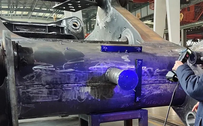
| Construction and mining equipment inspection | SANY Heavy Industry inspected large structural components of giant mining trucks using certified accuracy with photogrammetry-assisted volumetric accuracy of 0.02 mm + 0.015 mm/m, 1.85 million points per second and a 600 × 550 mm format | Volumetric accuracy over your largest component, outdoor or line-side operating conditions, and the marker strategy |
| Mould and tool inspection | A Thai mould and custom equipment maker cut per-part inspection from 30–45 minutes to 10–15 minutes with marker-free wireless scanning | Reverification interval, access to deep cavities and narrow features, and how mould wear is compared over time |
| Aerospace component quality control | An aircraft PMA component manufacturer moved from a 2–3 day CMM programming cycle to under half a day of setup, with no part-specific jigs | Traceability documentation, GD&T coverage against the drawing, and the reporting format required for component records |
| Electronic parts quality control | An EMI filter developer reduced prototype measurement from days or weeks to 2–3 hours and gained reusable full-surface data | Small-feature resolution, correct head class for small parts, and software compatibility with the existing QC platform |
| Ship hull and large-structure inspection | An aluminium-alloy hull was scanned to quantify dimensional deviation and welding-induced deformation against the design model | Measuring volume against section size, tracking method across long distances, and on-site power and mobility |
Limits and Fit Boundaries a Buyer Should State Up Front
A supplier that volunteers boundaries is easier to trust than one that only lists capabilities. Four boundaries deserve to be written into the technical specification rather than discovered later.
- CMM remains the laboratory reference. Coordinate measuring machines are still the recognised standard for absolute accuracy in an environment-controlled room. A scanning cell complements that role for large, complex, in-process or non-contact work; it does not replace a CMM in every case.
- Some surfaces still need preparation. Reflective, glossy or translucent parts may require an ultra-thin scanning spray even on metrology-grade equipment.
- A head certificate is not a cell certificate. Cell-level performance needs its own acceptance test, agreed in writing before commissioning.
- Tolerance class should drive head selection. SHINING 3D's selection guidance maps roughly 0.005–0.02 mm to functional safety parts and strict GD&T inspection, 0.02–0.05 mm to assembly verification and structural analysis, and 0.05–0.1 mm to overall deformation analysis and large cosmetic parts. These bands are a shortlisting aid, not a capability study on your part.
What a Verification-First Approach Changes
SHINING 3D's own account of the market is that machine vision is moving from 2D imaging to 3D perception, with improved data processing and computing power extending 3D vision from niche applications into mainstream industries. Read as a company statement rather than an independent market forecast, it points to a practical consequence for buyers: as scanning moves onto the line, the distinguishing question shifts from whether a supplier has a scanner to whether it can document what that scanner measures, on which configuration, and under which verification regime.
That is a procurement habit rather than a product feature. Plants that ask for the certificate scope, the software workflow, the cell acceptance definition and the reverification interval before signing tend to meet fewer surprises after commissioning — and take a shorter path from a rejected part to a defensible answer about why it was rejected.
FAQ
Can SHINING 3D issue accuracy certificates according to ISO 10360 or VDI/VDE 2634?
Yes. SHINING 3D states that it can issue calibration and accuracy certificates based on both VDI/VDE 2634 and ISO 10360 for its metrology-grade 3D scanners. The accuracy laboratory is accredited to ISO/IEC 17025 by CNAS, and because CNAS is a signatory to mutual recognition arrangements such as the ILAC MRA, certificates issued within that scope are recognised internationally. The laboratory is certified to perform accuracy tests and issue certificates under VDI/VDE 2634 Part 2 for single-view optical surface scanning and Part 3 for multiple-view systems, and SHINING 3D states that its testing systems and verification protocols align with ISO 10360-12 and ISO 10360-13 for acceptance and reverification testing.
What is the difference between accuracy, precision, resolution and volumetric accuracy?
Accuracy describes how closely a measured result matches the true dimension — measuring a 100.00 mm feature as 100.02 mm is a 0.02 mm error. Precision, or repeatability, describes how consistently the same measurement is reproduced under unchanged conditions. Resolution describes the smallest detail the scanner can distinguish, and higher resolution does not automatically mean higher accuracy. Volumetric accuracy describes measurement accuracy across a larger scanning volume; a specification such as 0.02 mm + 0.015 mm/m yields 0.05 mm over a 2 m object. For quality control purchasing, volumetric accuracy is the figure that should be matched to the largest dimension actually inspected.
How is a 3D scanner integrated into automated in-line inspection, and what should be verified before sign-off?
Integration combines a scanner head, a motion platform — robot arm, controller base and turntable — and inspection software, with results passed to the production system. Before sign-off, verify six things: that the optical technology matches the part surface and light conditions; that the measuring volume matches part size; that accuracy is certified to a recognised standard and traceable to an accredited laboratory; that tact time includes robot motion, frame capture, alignment and report generation; that the installed enclosure is rated for the vibration, temperature, dust and ambient light of that line; and that the software interface to PLC or MES, including the statistical process control feed, is delivered and tested rather than described.
What are the purchasing terms and acceptance criteria for a RobotScan deployment?
SHINING 3D's purchasing terms list a minimum order quantity of one unit, delivery terms of FOB, CFR, DAP or FCA, acceptance criteria of delivery inspection or post-installation acceptance, and payment terms of 100% advance payment or instalment payment. For an automated cell, post-installation acceptance is the more relevant of the two acceptance paths, because it is the point at which cell-level performance — rather than the scanner head alone — can be measured against the parts, features and tolerances named in the contract.
Have Questions or Need More Details?
Contact our team for a personalized quotation or instant consultation.
Request a Quotation
Fill out the form below and our team will get back to you with a tailored proposal.
WhatsApp Direct Chat
Prefer to chat in real-time? Message us on WhatsApp for instant assistance & quick answers.
- Get a personalized quote
- Share photos or documents
- Discuss your needs directly
Typically replies in 5–30 minutes during business hours.