
BESS Fire Safety and Backup Duration: A Project Engineer FAQ
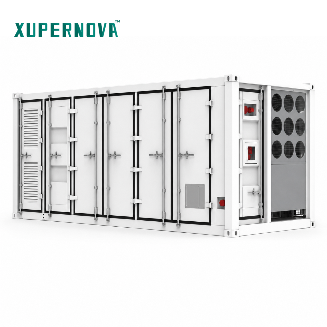
Liquid-cooled containerized battery energy storage systems are increasingly specified for utility-scale and critical-facility projects, where fire safety and backup duration have to be demonstrated at design review rather than assumed at commissioning.
Battery storage has left the pilot stage. Global new battery storage deployment reached 108 GW in 2025, according to the IEA Global Energy Review 2026, and LFP chemistry accounted for approximately 90% of those deployments. Once a technology reaches that volume, the engineering conversation shifts: the question is rarely whether a battery energy storage system can be installed, but whether a specific project can demonstrate that its system is fire-safe under local code and can genuinely deliver the backup duration drawn on the one-line diagram.
This technical FAQ is written for project engineers who are past the awareness stage and are now specifying, reviewing or commissioning an energy storage system. It covers fire-safety risk and mitigation architecture, the inputs that determine backup duration, islanding protection, black-start strategy, the assessments that must be closed before fire-safety sign-off, and the verification evidence that should travel with a shipment. Where a boundary exists, it is stated rather than smoothed over.
Why fire safety and backup duration decide the schedule
In critical-load backup and energy resilience projects, the formal requirement set is explicit: a critical-load assessment, a defined required backup duration, islanding protection, a black-start strategy, an emergency response plan and fire-safety compliance. None of these sit in the commercial package. They sit inside the electrical design package, which means they move the schedule rather than the price.
The consequences are asymmetric. A storage system that cannot close the fire-safety review cannot be energised, regardless of how competitive the quotation was. A system whose duration assumptions are wrong will pass every factory inspection and then fail at the first real outage — the worst possible moment to discover the gap. Both questions therefore belong at design freeze, not at handover.
Fire safety in a battery energy storage system: how the protection layers stack
Thermal events in storage are not spontaneous. In the risk model applied to these projects, fire and thermal-runaway risk is triggered by abnormal cell temperature, an internal short circuit, or thermal-propagation conditions arising during normal system operation. That is why fire safety is engineered as an architecture rather than selected as a single component.
| Protection layer | What it does at project level | Evidence to request from the supplier |
|---|---|---|
| Multi-level temperature monitoring with BMS protection | Detects abnormal cell temperature and out-of-window operation, then isolates the affected section | BMS protection logic, alarm thresholds, communication protocol documentation |
| Liquid cooling | Continuously removes heat from modules; in applicable liquid-cooled models, cell temperature difference is controlled within 3 °C | Thermal design description and factory test records |
| Smoke and temperature detection | Provides early warning before propagation conditions develop | Detector types and placement drawing |
| PACK-level and cluster-level aerosol fire suppression | Suppresses an event at module pack level and at cluster level | Suppression agent, coverage definition and activation logic |
| Water fire-fighting interface | Allows the site fire service to apply water through a defined connection point | Interface location, water-flow requirement and site coordination procedure |
| Automatic alarm and emergency shutdown | De-energises and alarms in a defined sequence, coordinated with PCS and EMS | Shutdown sequence diagram and interlock list |
| LFP cells | Chemistry that dominates the installed base — approximately 90% of 2025 deployments, per the IEA | Cell supplier, datasheet and Grade A LFP confirmation |
Read as a chain, the sequence runs from detection, through BMS action and cooling, to suppression and shutdown, and finally to the interface the fire service will use on site. Each link has a testable artefact, which is what makes the architecture reviewable.
Backup duration: the inputs that must be fixed before sizing
Backup duration is the second question that shapes the electrical design, and it is the one most frequently answered too early with a single number.
1. Critical-load assessment: deciding what the battery is responsible for
A duration figure is meaningless until the critical-load list is fixed. In critical-facility projects, the working definition is the set of loads that must remain energised during grid outages and emergencies — typically a subset of the site, not the whole facility. The matched-equipment list for this scenario is an effective checklist of what a duration claim actually depends on: an STS or EPS cabinet, a critical-load distribution panel, a grid-forming PCS, a transformer if required, switchgear, a UPS for zero-interruption loads, an EMS and an optional diesel generator.
That list already contains two engineering decisions. The STS or EPS defines how the critical bus is separated from the main bus. The UPS defines which loads cannot tolerate any transfer time at all and must therefore be excluded from the battery sizing calculation or covered separately.
2. From energy capacity to delivered duration
| Platform | Configuration | Energy and power | Typical fit |
|---|---|---|---|
| XA-V5015-L1 | 20-ft liquid-cooled battery container | 5.015 MWh, 0.5P/1P/2P | Utility-scale and grid-side energy storage |
| XA-X2170-L2 | 20-ft liquid-cooled all-in-one ESS container | 1125 kW / 2170.3 kWh, 0.5P/1P/2P | Grid-side and large commercial and industrial storage |
| XA-X1044-L1 | 10-ft liquid-cooled all-in-one ESS container | 500 kW / 1044 kWh, 0.5P/1P/2P | Microgrids and backup power |
| XA-C0261-L1 | Liquid-cooled all-in-one ESS cabinet | 125 kW / 261.25 kWh, 0.5P/1P/2P | Commercial and industrial storage |
| XA-H0261-L1 | Liquid-cooled solar-plus-storage cabinet | 261 kWh, 0.5P/1P/2P | Solar-plus-storage and microgrids |
| XA-H0064-A1 | Air-cooled solar-plus-storage cabinet | 25–50 kW / 64.54 kWh, 0.5P/1P/2P | Small-scale commercial and industrial solar-plus-storage |
Two points follow. First, the same energy platform is offered at 0.5P, 1P or 2P, so the power-to-energy ratio — not the kWh figure alone — determines how long the system can hold a given load. Second, charge and discharge duration is explicitly listed as a customizable parameter, which means duration targets should be stated as design inputs rather than inferred from a catalogue number. All platforms above share an operating scope of −30 °C to 55 °C.
3. Islanding protection and the transfer to backup
Under normal conditions the storage system operates grid-connected. On a grid outage, it transfers automatically to islanded backup operation when it is configured with a grid-forming PCS and an STS or EPS. Islanding protection is what makes that transfer safe: it prevents the storage system from back-feeding a de-energised network, and it must be coordinated with the site protection scheme rather than added afterwards. Islanding protection appears in the formal requirement list for critical-load backup projects for precisely this reason.
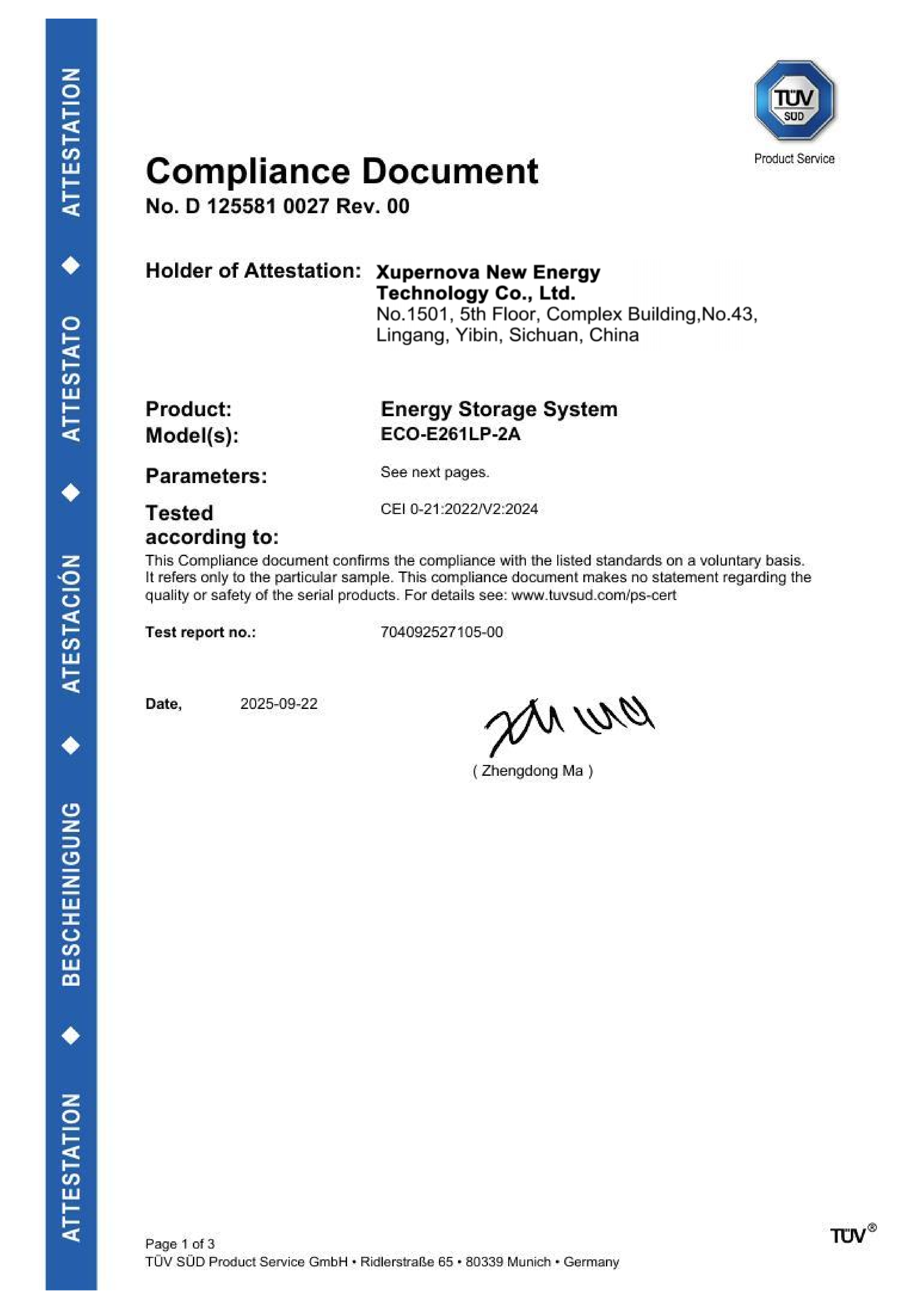
CEI 0-21:2022/V2:2024 compliance document for the ECO-E261LP-2A energy storage system, issued by TÜV SÜD Product Service GmbH (certificate D 125581 0027 Rev. 00, issued 22 September 2025) for the Italian market.
In markets with prescriptive connection rules, islanding and connection behaviour is also a grid-code question. For Italy, Xupernova holds CEI 0-21 and CEI 0-16 compliance documents for the ECO-E261LP-2A. Other projects reference different regimes depending on location — a renewable energy developer project in the case portfolio was delivered with G99 grid-code compatibility, and an industrial manufacturing deployment with German grid requirements.
4. Black-start strategy
Black-start capability is the ability to energise the system and establish a reference for the local network without relying on an external grid. In remote mining microgrids and off-grid industrial sites, black-start capability and remote O&M are stated site requirements. In critical-load backup, the black-start strategy belongs in the same package as the emergency response plan. This is where storage, diesel generators, PV and load sequencing meet, which is why the EMS and the source-scheduling logic carry as much weight as the battery itself.
How Xupernova covers these requirements within a project scope
Xupernova New Energy Technology Co., Ltd. (Xupernova) is an energy storage and new energy solutions provider founded in 2015, manufacturing energy storage systems from a 700,000 m² base with more than 500 employees, over 150 R&D engineers and 5 GWh+ annual capacity. Around 90% of output is exported to Europe, North America, South America, the Middle East and Asia, and monthly production capacity reaches up to 500 MWh per month.
The customization scope is where fire safety and duration requirements are translated into a buildable specification. Configurable parameters include system power and energy capacity, charge and discharge duration, AC and DC voltage, battery chemistry and cell supplier, PCS, BMS and plant-level EMS, photovoltaic input and solar-plus-storage configuration, on-grid and off-grid operation, STS/EPS backup function, cooling system, fire protection system, enclosure size, colour and branding, IP rating and corrosion protection, grid code, communication protocols, and transformer and switchgear configuration. OEM and ODM production services are available, with a minimum order quantity of one unit. Standard BESS lead time is 25–35 days; customized projects run 35–60 days.
Quality control is structured around evidence rather than assertions: 100% factory acceptance testing before shipment, plus electrical safety testing, functional testing and aging testing, with third-party inspection available. After-sales coverage includes 24/7 remote support, commissioning, training, diagnostics, spare parts and optional onsite service.
| Certificate | Standard | Scope | Authority and status |
|---|---|---|---|
| IEC 63056:2020 product certificate | IEC 63056:2020 | Rechargeable Li-ion battery system, model ECO-E261LP-2A(DC), DC 832 V, 314 Ah | TÜV SÜD Product Service GmbH; B 125581 0022 Rev. 01, issued 16 September 2025 |
| LVD attestation of conformity | EN 62477-1:2012/A12:2021 | Energy storage system, model ECO-E261LP-2A, 125 kW, 261.248 kWh, IP55 | TÜV SÜD Product Service GmbH; N8A 125581 0024 Rev. 00, issued 1 September 2025 |
| EMC attestation of conformity | EN IEC 61000-6-4:2019; EN IEC 61000-6-2:2019 | Energy storage system, model ECO-E261LP-2A, 125 kW, 261.248 kWh, IP55 | TÜV SÜD Product Service GmbH; E8A 125581 0023 Rev. 00, issued 22 July 2025 |
| CEI 0-21 compliance document | CEI 0-21:2022/V2:2024 | Energy storage system, model ECO-E261LP-2A, Italy | TÜV SÜD Product Service GmbH; D 125581 0027 Rev. 00, issued 22 September 2025 |
| CEI 0-16 compliance document | CEI 0-16:2022/V3:2024 | Energy storage system, model ECO-E261LP-2A, Italy | TÜV SÜD Product Service GmbH; D 125581 0028 Rev. 00, issued 22 September 2025 |
Where these answers are tested: application scenarios
| Scenario | Defined requirement |
|---|---|
| Critical facilities — hospitals, data centres, government facilities and emergency services | Critical-load assessment, required backup duration, islanding protection, black-start strategy, emergency response plan and fire-safety compliance |
| Commercial, industrial and manufacturing facilities | Load-profile assessment, time-of-use tariff analysis, grid-connection approval, protection coordination and fire-safety compliance |
| Solar-plus-storage and photovoltaic self-consumption | PV generation assessment, export limitation, grid-code compliance, backup-load assessment and coordinated PV-battery control |
| Remote mining microgrids and off-grid sites | Site load study, motor-starting analysis, spinning-reserve strategy, high-temperature and dust protection, black-start capability and remote O&M |
| Utility-scale renewable integration | Grid impact study, local grid-code compliance, protection coordination, dispatch interface, cybersecurity, fire safety and environmental assessment |
Reference deployments show how these inputs translate into configuration. A commercial and industrial park operator configured 12 units totalling 1 MW / 2.088 MWh for a solar-plus-storage microgrid with integrated STS, grid-connected and off-grid switching, PV and diesel generator interfaces and centralised energy management; after seven years of operation the reported outcomes were improved critical-load power continuity, higher solar utilisation and reduced diesel generator runtime. An industrial manufacturing enterprise deployed 20 units totalling 1 MW / 2.09 MWh for peak shaving and demand management under German grid requirements, with stable automatic operation reported over two years. A supermarket and retail facility operator uses 50 units of 125 kW / 261.248 kWh for peak shaving, time-of-use energy arbitrage and photovoltaic self-consumption, with compatibility with Italian grid requirements.
Market trend analysis: what the numbers mean for design review
The IEA reports 108 GW of new battery storage capacity deployed globally in 2025, while the U.S. Energy Information Administration projects 19.6 GW of utility-scale battery storage capacity growth in the United States in that year. LFP chemistry accounted for roughly 90% of global deployments in 2025, which is consistent with the LFP specification across the platforms discussed above.
Cost trajectories reinforce the trend. All-in project CAPEX for long-duration (4h+) utility-scale projects reached USD 125/kWh in late 2025, according to Ember — for projects outside China and the United States. MarketsandMarkets estimates the global BESS market at USD 50.81 billion in 2025, although published valuations for the same year diverge considerably between research houses because some count the full system value chain, including PCS, EMS and civil works, while others count battery equipment alone. Engineers reading market figures should attach the scope definition before using them in business cases.
One procurement detail also deserves engineering attention: battery energy storage systems fully encased in housing are classified under US HTS 8507.60.00.90 in the Harmonized Tariff Schedule 2026 published by the U.S. International Trade Commission. Classification affects landed cost and should be settled before the layout, not after.
The combined effect is a shift in the binding constraint. Falling cost per kWh has moved the bottleneck from capital to compliance: more projects now pass through grid-code review, fire-safety sign-off and insurance scrutiny, where the ability to document an architecture matters more than the ability to quote a capacity.
Battery storage versus diesel and UPS: where each still wins
| Requirement | Diesel generator | UPS | Battery energy storage system |
|---|---|---|---|
| Runtime model | Limited by fuel logistics and refuelling access | Short-duration support for zero-interruption loads | Defined by configured energy and power-to-energy ratio |
| On-site emissions and combustion | Present during operation | None | None during discharge |
| Transfer behaviour | Requires start and transfer sequence | Bridges transfer time only | Automatic transfer to islanded backup with grid-forming PCS and STS/EPS |
| Additional services | Standby power only | Power conditioning and short ride-through | Peak shaving, time-of-use arbitrage, solar self-consumption, renewable shifting |
| Coexistence | Optional backup source alongside storage | Retained for zero-interruption loads | Coordinates with both through the EMS |
The comparison is not a ranking, because the three technologies answer different questions. What matters for engineering is where the battery system does not simply replace the alternatives.
First, a battery system cannot extend its own stored energy within a given configuration; adding duration means adding capacity, changing the power-to-energy ratio, or accepting load management. Second, storage does not remove the need for a UPS on loads that cannot tolerate any transfer time — the UPS for zero-interruption loads appears in the matched-equipment list alongside the storage system, not instead of it. Third, thermal management assumptions are configuration-specific: the controlled 3 °C cell temperature difference applies to the applicable liquid-cooled models, while the air-cooled solar-plus-storage cabinet addresses smaller installations on a different thermal basis. Fourth, diesel generators remain in the architecture where extended runtime or legacy infrastructure requires them, as in the microgrid case where PV, storage and diesel operate under a single microgrid controller. Finally, fire-safety compliance is a site-specific approval, not a product feature: the same platform may require different documentation in different jurisdictions.
Future outlook
Two directions are already visible in current specifications. The first is chemistry diversification beyond LFP: optional semi-solid-state, solid-state and sodium-ion battery technologies are available on the Xupernova platforms, subject to project requirements, technical validation and availability. Each of those paths carries its own validation obligations, which is why they are gated on technical validation rather than offered as catalogue defaults.
The second is documentation-driven procurement. As grid codes tighten and fire-safety sign-off becomes a standard gate, the engineering deliverables — protection coordination studies, islanding and black-start strategies, third-party inspection records and site acceptance testing — increasingly determine which suppliers can complete a project rather than which can start one. For project engineers, that reframes the specification: the objective is not a battery with the best headline number, but a system whose fire-safety architecture and duration assumptions can be defended in front of the authority having jurisdiction.
Frequently asked questions
What are the fire-safety risks of a battery energy storage system?
The identified risks are fire and thermal runaway. In the risk model applied to these projects, thermal events are triggered by abnormal cell temperature, an internal short circuit, or thermal-propagation conditions during system operation. Mitigation is layered rather than singular: multi-level temperature monitoring, BMS protection, liquid cooling, automatic alarm and emergency shutdown are combined with multi-layer fire-suppression hardware. The suppression layer typically includes LFP cells, smoke and temperature detection, PACK-level and cluster-level aerosol fire suppression, and a water fire-fighting interface; for applicable liquid-cooled models, cell temperature difference is controlled within 3 °C.
How is the required backup duration determined for a critical facility?
It begins with a critical-load assessment, which fixes the subset of site loads that must remain energised during a grid outage. The required backup duration is then expressed against that load list, and matched by the configured energy at the specified power-to-energy ratio. The supporting architecture is defined in the same exercise: an STS or EPS cabinet, a critical-load distribution panel, a grid-forming PCS, a transformer if required, switchgear, a UPS for zero-interruption loads, an EMS and an optional diesel generator. Required backup duration is one of the formal requirements in critical-load backup projects and should be documented before equipment is specified.
What is islanding protection, and why does the project need it?
Islanding protection prevents a storage system from back-feeding a de-energised network when the grid is down, and it is part of the site protection coordination. It is what allows the system to move safely from grid-connected operation to islanded backup operation, a transfer that occurs automatically when the system is configured with a grid-forming PCS and an STS or EPS. Because islanding behaviour interacts with local connection rules, it is normally reviewed together with grid-code compliance for the specific market.
What does a black-start strategy include?
A black-start strategy defines how the storage system energises itself and establishes a reference for the local network without an external grid, and in what order loads and other generation sources are brought back. In remote mining microgrids and off-grid industrial sites, black-start capability and remote O&M are stated site requirements, supported by a site load study, motor-starting analysis and a spinning-reserve strategy. In critical-load backup, the black-start strategy is grouped with the emergency response plan.
Which assessments should be closed before fire-safety sign-off?
For critical-load backup projects, the requirement set is a critical-load assessment, the required backup duration, islanding protection, a black-start strategy, an emergency response plan and fire-safety compliance. For utility-scale renewable integration, the corresponding set includes a grid impact study, local grid-code compliance, protection coordination, dispatch-interface requirements, cybersecurity, fire safety and environmental assessment. Fire-safety sign-off therefore sits inside a broader package of study work rather than standing alone.
How do chemistry and cooling choices affect both fire risk and backup duration?
LFP is the dominant chemistry in deployed storage, accounting for approximately 90% of global deployments in 2025 according to the IEA, and it is the base chemistry across the Xupernova platforms, which use Grade A LFP lithium-ion cells from leading BloombergNEF Tier 1 energy-storage cell manufacturers. Thermal management then determines how evenly that chemistry is operated: applicable liquid-cooled models control cell temperature difference within 3 °C, while the air-cooled solar-plus-storage cabinet addresses smaller installations with a different thermal design. Semi-solid-state, solid-state and sodium-ion options are available subject to project requirements, technical validation and availability.
What acceptance evidence should engineers require before shipment?
Factory acceptance testing is the baseline: 100% FAT before shipment, together with electrical safety testing, functional testing and aging testing, with third-party inspection and site acceptance testing available. Typical commercial terms are a minimum order quantity of one unit, delivery under EXW, FOB, CIF, DAP or DDP, and payment of 30% deposit with 70% before shipment after FAT. On certification, engineers should verify both model scope and market scope: the Xupernova documents cover the ECO-E261LP-2A, with LVD and EMC attestations for the EU and CEI 0-21 and CEI 0-16 compliance documents for Italy.
A consolidated product catalogue covering the energy storage platforms referenced in this FAQ is available for download: https://cdn.socialarks.com/sbsp/25227/common/2026/0827/XUPERNOVA_Energy_Storage_Product_Catalog.pdf