
Brushless Motor FAQ: Load Capacity, Coreless vs Iron-Core, Duty Fit
Torque, not voltage, decides whether a brushless motor fits a project, and it is the number buyers most often read incorrectly. A published figure such as 30.0 kg.cm is a ceiling created by a specific combination of gear ratio, winding and supply voltage. Change one of those and the load capacity available at the output shaft changes with it.
This FAQ works through the three questions that recur in nearly every miniature motor evaluation: how much load a brushless motor can carry, how a coreless motor differs from a conventional iron-core motor, and whether brushless or brushed construction suits equipment that runs for long periods. A fourth question sits underneath all three, and it is the one that decides whether an approved sample survives into production: how much of a datasheet can be reproduced batch after batch. The answers are grounded in documented specifications from TT Motor (Shenzhen) Industrial Co., Limited, a Shenzhen-based manufacturer of miniature DC motors founded in 2006, with a 9,000 sqm manufacturing area, more than 300 employees and an annual output of 8,000,000 pieces.
Short answers
Load capacity is published as rated torque, the torque that can be continuously output under specified operating conditions, and it is only valid at the stated voltage, ratio and speed.
Coreless motors differ from iron-core motors in the rotor: no iron core means lower inertia, no cogging, faster response and lower interference, but also a lower torque ceiling and, in the documented GMP12T-TDC1215, a brushed construction rather than a brushless one.
For continuous duty, brushless construction removes brush wear, but gear train, lubrication and thermal limits still define service life.
Sample approval and batch consistency are governed by configuration control and agreed measurement conditions, not by the datasheet alone.
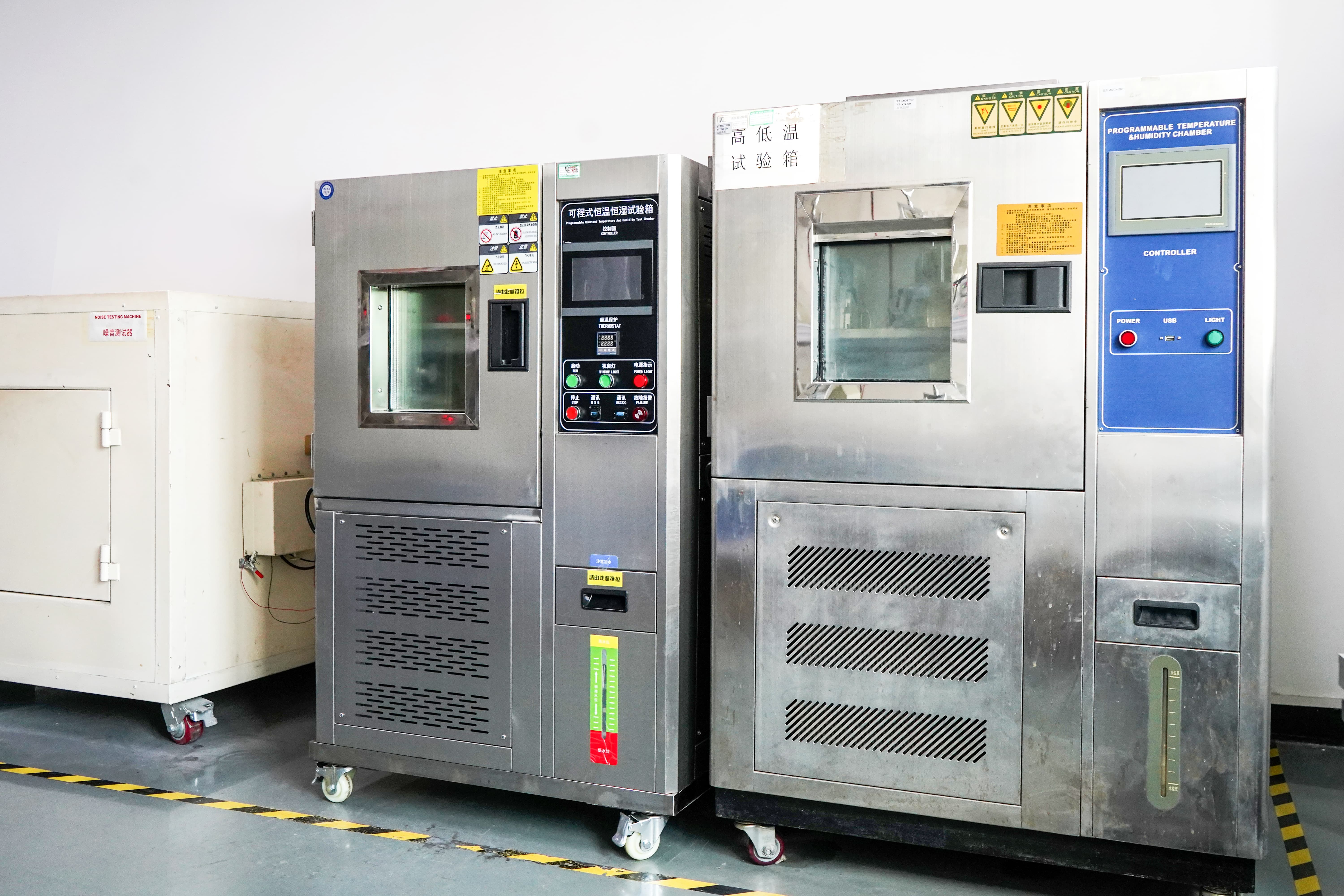
What Load Capacity Means on a Brushless Motor Datasheet
Rated torque is the torque that can be continuously output under specified operating conditions. The qualifier carries the weight. A rated torque figure is only meaningful together with the voltage, the gear ratio and the speed at which it applies, which is why a supplier cannot answer the question of what load a motor handles with one number for an entire product family. The documented position is that different motors carry different loads, and that ratio, winding and voltage can be adapted to a specific project.
Within the miniature ranges documented by TT MOTOR, published maximum rated torque spans roughly two orders of magnitude:
| Model | Construction | Max rated torque | Rated voltage | Speed range | Gear stages | Gearbox length |
|---|---|---|---|---|---|---|
| GMP36-TEC3650 | Brushless planetary gear motor | 30.0 kg.cm | DC 12V-24V | 4-1600 rpm | 1-4 | 26 / 33.5 / 40.5 / 47.5 mm |
| TWG3246-TEC2430 | Brushless worm gear motor | 8.0 kg.cm | DC 12V-24V | 3-35 rpm | 3 / 4 / 5 | 46 mm |
| GMP12T-TDC1215 | Coreless gear motor | 2 kg.cm | DC 4.5V-12V | 8-5000 rpm | 1-4 | 14.9 / 19.7 / 24.5 / 29.3 mm |
| GM37-555PM | Brushed spur gear motor | 8.0 kg.cm | DC 12V-24V | 5-800 rpm | 2-6 | 19-29 mm |
| GM12-N20VA | Brushed spur gear motor | 0.5 kg.cm | 2.4V / 5V | 12-1450 rpm | 2 / 4 / 5 / 7 | 9 / 12 mm |
The 30.0 kg.cm ceiling belongs to a 36 mm brushless planetary gear motor weighing 420 g, with an 8 mm solid output shaft and 4-M3 flange mounting holes. The 0.5 kg.cm ceiling belongs to an N20-class spur gear motor used for smart-home drive applications. Neither figure is a statement about brushless motors as a category. Both are statements about a specific frame size, gear train and winding, and the sixty-fold difference between them is a difference in design intent rather than in quality.
Why a Torque Rating Does Not Travel Between Configurations
Three variables move the usable load at the shaft, and procurement teams that treat a torque figure as a fixed property usually end up re-specifying after the first prototype.
Gear ratio and stage count come first. GMP36-TEC3650 is offered with 1 to 4 gear stages and 10 reduction ratios from 1/4 to 1/720, with gearbox lengths of 26, 33.5, 40.5 and 47.5 mm depending on stage count. GM37-555PM supports 2 to 6 stages across 10 ratios from 1/6 to 1/810. Higher ratios multiply output torque and divide output speed, so the same motor can serve as a fast low-torque axis or a slow high-torque one without any change to the frame.
Supply voltage and winding come second. GMP36-TEC3650 is rated for DC 12V to 24V and covers 4 to 1600 rpm; GMP12T-TDC1215 is rated for DC 4.5V to 12V and covers 8 to 5000 rpm. A 12 V build and a 24 V build of the same frame are not interchangeable at the same operating point, and a winding selected for one supply will not deliver the same torque curve on another.
Operating point comes third. Maximum rated torque is a gearbox ceiling, not a value available at every speed in the range. A robot joint that needs high torque at 4 rpm is asking a different question from a conveyor drive that needs moderate torque at several hundred rpm, and the answer changes with the ratio selected.
The practical rule is to specify the requirement, not the model: required output torque, output speed, reflected inertia and duty profile first; ratio and winding second. Documented OEM/ODM customization covers shaft, encoder, gearbox, voltage, logo and speed, which is what makes that sequence workable in practice.
Coreless vs Iron-Core: The Difference Sits in the Rotor
A conventional iron-core motor winds its coils into slots cut in a laminated steel rotor. A coreless motor replaces that assembly with a self-supporting winding that rotates without an iron core. The magnetic circuit is different, and so is almost everything the application feels as a result.
Rotor inertia drops sharply. Lower inertia is the mechanism behind fast response: with a heavy rotor, a stop command is followed by residual rotation and overshoot, because the rotor keeps turning after the drive has acted; with a light rotor, the command-response-stop cycle closes much faster. This is the engineering reason coreless motors appear in robot joints and other axes where high power density, fast response and low inertia are listed as the special requirements, and it is why they suit high-frequency start-stop motion rather than steady high-load work.
Cogging disappears. A slotted rotor produces torque ripple as its teeth pass the magnets; a coreless rotor has no such teeth to generate it. The visible results are smoother low-speed rotation, quieter operation and, as documented for GMP12T-TDC1215, virtually no electromagnetic interference. That last property matters in pipetting equipment, urine and body fluid analyzers and other precision medical instruments, where low noise, low vibration and stable operation are explicit requirements rather than preferences.
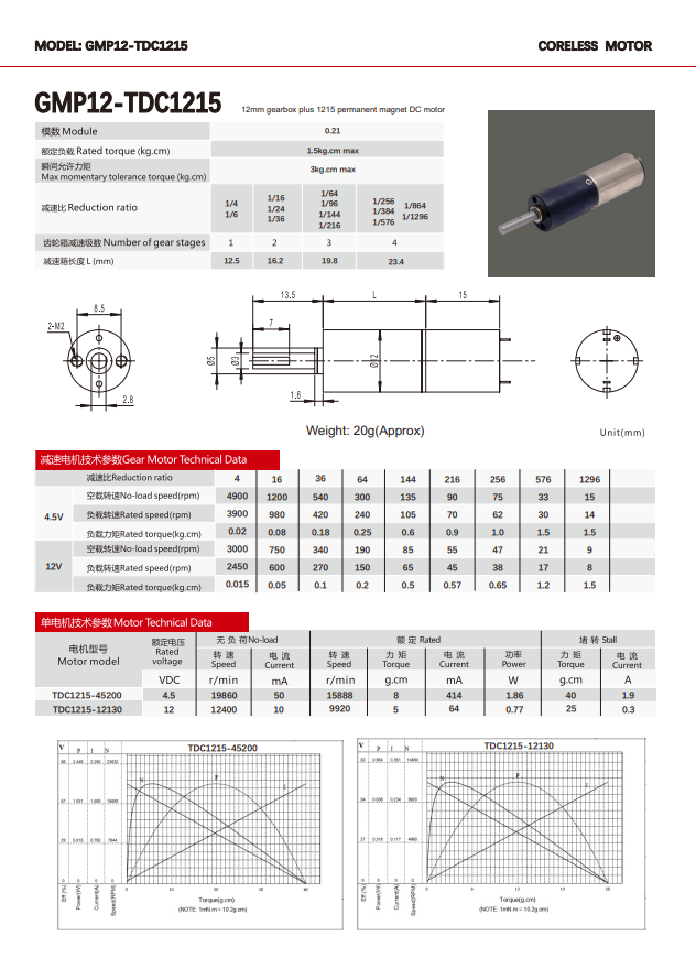
The documented coreless example in this range is GMP12T-TDC1215: 2 kg.cm maximum rated torque, module 0.2 gearing, 1 to 4 gear stages, gearbox lengths of 14.9, 19.7, 24.5 and 29.3 mm, DC 4.5V to 12V and 8 to 5000 rpm. A dental instrument manufacturer in Japan uses it to drive micro positioning and adjustment mechanisms at 500 to 2,000 units per year over three to five years, with rapid response and improved equipment control precision reported as outcomes.
The limits are equally concrete, and four of them decide whether a coreless design is the right answer.
First, the torque ceiling is lower. Two kg.cm against 30.0 kg.cm for the 36 mm brushless planetary unit is a structural difference, not a tuning difference. Coreless construction buys response and smoothness in a very small envelope; it does not buy raw load capacity.
Second, heat leaves a coreless winding by a different path than in a slotted rotor, because there is less iron to conduct it toward the housing. Thermal behaviour under sustained high load has to be confirmed by test rather than inferred from the torque number.
Third, coreless construction generally carries a higher cost per unit of output torque at the same frame size, which is why it tends to appear where response or silence justifies the premium rather than in cost-driven volume drives.
Fourth, and most often missed in procurement: coreless is not the same as brushless. GMP12T-TDC1215 is documented as a DC brush coreless gear motor, so it still contains a brush system, and brush wear remains part of its life budget. A buyer who selects coreless expecting brushless endurance has selected on the wrong attribute.
Continuous Duty: Where Brushless and Brushed Actually Diverge
Long-running equipment turns the construction choice into a maintenance decision rather than a performance one. A brushless motor removes the brush and commutator contact that physically wears in a brushed motor. TT MOTOR documents GMP36-TEC3650 as having a lifespan far exceeding that of brushed motors of the same size, typically tens of thousands of hours, and as requiring no regular brush replacement.
That does not make brushed motors obsolete. GM37-555PM and GM12-N20VA are brushed DC gear motors, and both are used in low-speed, intermittent, positioning duty: smart-home drives, analyzers, lock mechanisms. In that duty, the drive is simple, the system cost is low and the motor is not running continuously. A smart-lock programme supplied for more than five years shows that a brushed gear motor can satisfy a high-frequency unlocking and locking requirement when the duty is intermittent rather than continuous, and that a documented long supply relationship is itself a form of reliability evidence.
Brushless construction becomes the better fit when the axis runs for long periods, when maintenance access is poor, or when frequent start-stop cycles under load are normal. A medical device manufacturer in the United Kingdom drives medical pumps with GMP36-TEC3650 at 500 to 2,000 units per year over three years or more, reporting stable output under long-term operating conditions and reduced equipment maintenance frequency. A logistics equipment customer in the United States runs 1,000 units on conveyor and sorting mechanisms for three years or more, with stable operation under frequent start-stop and load changes. Both are duty profiles where brush replacement would be an operational problem rather than a service item.
The boundary deserves to be stated plainly. Brushless construction changes which component wears; it does not remove life limits from the assembly. Gearbox gears, bearings, lubrication and the thermal ageing of insulation and electronics continue to set service life, and in high-ratio, high-torque builds the gear train is frequently the limiting element rather than the motor itself. Brushless also requires commutation electronics, which adds design effort and cost that a directly driven brushed motor does not carry. For a low-duty axis inside a cost-sensitive enclosure, a brushed gear motor can remain the rational engineering choice, and asking for brushless by default can add cost without adding capability.
Sample Approval vs Batch Consistency
The most common procurement anxiety about brushless motors is not the datasheet. It is the gap between the unit that passed evaluation and the units that arrive in production. The documented supply parameters frame the problem: samples in 15 to 25 days, bulk in 30 to 45 days, 100% test on production, monthly capacity of 800,000 pieces and a minimum order of 2 pieces.
A sample is a single build; a batch is a distribution. Four things commonly move between them: the ratio and stage count actually built, the winding used for the specified voltage, the tolerance stack in the gear train, and the test conditions under which torque and speed were measured. An approved sample measured at one voltage and one speed does not automatically define acceptance for a batch measured at another, and a specification written as a model number alone leaves all four variables open.
Three practices close most of the gap. Fix the configuration in writing, so that the approved sample and the production order describe the same object: ratio, stage count, voltage, shaft, encoder, connector and mounting interface. Define the acceptance window numerically: measured torque at a stated speed and voltage, no-load current, running noise and vibration, gearbox backlash, and the critical dimensions. Then agree the measurement conditions themselves, because 100% testing is a defect screen and not a substitute for a shared test standard.
Two details are easy to specify and easy to forget. The first is the mechanical interface: an 8 mm shaft and 4-M3 flange holes on GMP36-TEC3650, a standard flange for integration into very small devices on GMP12T-TDC1215. The second is the noise and vibration signature, which is usually the first parameter to drift in a gear train and the last to appear on a purchase drawing. Buyers who record both at sample approval have a usable acceptance reference for every later batch; buyers who record only torque do not.
Matching Motor Type to Project Conditions
The same three variables, torque ceiling, rotor behaviour and duty, map onto documented applications as follows.
| Project condition | Documented requirement | Documented fit | What to verify before approval |
|---|---|---|---|
| Robot joints | High power density, fast response, low inertia, high-frequency start and stop | GMP36-TEC3650 at 30.0 kg.cm, DC 12V-24V, 4-1600 rpm, 1-4 stages | Short-term peak load margin, reflected inertia, encoder integration |
| Pipetting and analyzer equipment | Low-speed precision motion, low noise, low vibration, long-term operation | GMP12T-TDC1215 for pipetting; GM37-555PM for urine and body fluid analyzers | Noise and vibration at the working speed, positional repeatability |
| Medical pumps | Stable output over long operating periods, reduced maintenance | GMP36-TEC3650, supplied at 500-2,000 units per year for three years or more | Temperature rise under continuous running, duty profile definition |
| Surgical staplers and rehabilitation robots | Low noise and low vibration during long-term intermittent positioning | GMP36-TEC3650 | Acoustic signature, gear stage selection |
| Smart-home drives | Miniaturization, low noise, low power consumption, low-speed positioning | GM12-N20VA at 0.5 kg.cm, 2.4V or 5V, 12-1450 rpm | Torque margin at the actual supply voltage, life at the unlock frequency |
| Right-angle or self-locking adjustment | Holding position without an extra brake, slow fine adjustment | TWG3246-TEC2430 at 8.0 kg.cm, DC 12V-24V, 3-35 rpm | Holding behaviour under reverse load, backlash |
| Micro positioning instruments | Rapid response, low inertia, compact envelope | GMP12T-TDC1215 at 2 kg.cm, 8-5000 rpm | Overshoot behaviour at the commanded step, thermal margin |
The pattern is consistent: where the requirement is load, the larger brushless frame with a multi-stage planetary gearbox is the fit; where the requirement is response in a small envelope, the coreless unit is the fit; where the requirement is cost-controlled intermittent motion, a brushed gear motor remains viable.
Market Context: A Larger Category, More Specific Questions
The scale of the category explains why these questions are asked more often than they were a decade ago. Grand View Research reports the global brushless DC motor market at approximately USD 22.2 to 22.33 billion in 2025, with a forecast period running from 2026 to 2033. OEC records USD 16.3 billion in global trade of electric motors with an output below 37.5 W under HS 850110 in 2024, the customs bracket that contains most miniature gear motors.
Regulation, meanwhile, has moved in a direction that leaves miniature motors outside its efficiency bands. EU Ecodesign Regulation (EU) 2019/1781 sets IE3 for the 0.75-1000 kW range and IE2 for 0.12-0.75 kW, and IEC 60034-30-1:2025 adds the IE5 class. Both begin at 0.12 kW, well above the motors discussed here, so efficiency evidence for miniature gear motors comes from supplier test data and batch documentation rather than from a regulated efficiency class. That is one reason buyers increasingly ask for measured values at a defined operating point instead of a category claim, and it is a reasonable shift: an efficiency class cannot be quoted for a 0.5 kg.cm smart-home gear motor, but a torque and current measurement at the application voltage can be.
What to Expect Next
Two expectations are reasonable to plan around without forecasting specific figures. The first is that duty-cycle evidence will become a standard part of miniature motor procurement rather than an optional extra, because the applications driving volume, medical devices, robotics and logistics handling, are exactly the ones where maintenance access is expensive. The second is that the coreless and brushless categories will keep being conflated in early-stage sourcing conversations until buyers separate rotor construction from commutation method in their own specifications. Suppliers who document both attributes, and who can tie them to measured batch data, will be easier to shortlist than those who publish a single headline torque figure.
FAQ
What load can a brushless gear motor handle?
There is no single answer across a product family, because the load figure depends on frame size, gear ratio, winding and voltage. Documented maximum rated torque in the TT MOTOR range runs from 30.0 kg.cm for GMP36-TEC3650 (DC 12V-24V, 4-1600 rpm, 1 to 4 gear stages) down to 0.5 kg.cm for GM12-N20VA (2.4V or 5V, 12-1450 rpm). Rated torque is the torque that can be continuously output under specified operating conditions, so it should be compared at the speed and voltage the application actually uses.
How does a coreless motor differ from an iron-core motor?
The difference is in the rotor. An iron-core motor winds its coils into slots in a laminated steel rotor; a coreless motor uses a self-supporting winding with no iron core. The practical consequences are lower rotor inertia, and therefore faster response with less overshoot; no slot cogging, and therefore smoother low-speed rotation and lower noise; and lower electromagnetic interference. GMP12T-TDC1215 documents these properties at 2 kg.cm maximum rated torque, DC 4.5V-12V, 8 to 5000 rpm, in gearbox lengths from 14.9 to 29.3 mm.
Are brushless motors the right choice for continuous operation?
For long-running axes, usually yes. A brushless motor has no brush and commutator wear, and GMP36-TEC3650 is documented with a lifespan far exceeding brushed motors of the same size, typically tens of thousands of hours, without regular brush replacement. For intermittent low-speed positioning, a brushed gear motor can remain appropriate and simpler to drive. The decision depends on duty cycle, thermal conditions, maintenance access, and whether commutation electronics are acceptable within the system.
Why can an approved sample fail to match the production batch?
Because a sample is one build and a batch is a distribution. Ratio and stage count, the winding used for the specified voltage, gear-train tolerance, and the test conditions used for measurement can all differ between them. The countermeasure is a written configuration, numeric acceptance windows for torque, current, noise, backlash and dimensions, and agreed measurement conditions. Documented lead times are 15 to 25 days for samples and 30 to 45 days for bulk, with 100% test on production.
Can a motor be adapted to a different load and speed requirement?
Yes. Documented OEM/ODM customization covers shaft, encoder, gearbox, voltage, logo and speed, with a minimum order of 2 pieces. Changing the gear ratio changes torque and speed together: GMP36-TEC3650 offers 10 ratios from 1/4 to 1/720 across 1 to 4 stages, and GMP12T-TDC1215 offers 1 to 4 gear stages. The requirement is therefore best stated as a torque, speed, inertia and duty profile rather than as a preferred model number.
A downloadable PDF catalogue covering the miniature DC, brushless, coreless, planetary, spur and worm gear motor ranges, with model-level specifications, is available here: TT Motor product catalogue (PDF).
Have Questions or Need More Details?
Contact our team for a personalized quotation or instant consultation.
Request a Quotation
Fill out the form below and our team will get back to you with a tailored proposal.
WhatsApp Direct Chat
Prefer to chat in real-time? Message us on WhatsApp for instant assistance & quick answers.
- Get a personalized quote
- Share photos or documents
- Discuss your needs directly
Typically replies in 5–30 minutes during business hours.