
CNC and Die Casting Scenario Fit: Housings, Heat Sinks, Enclosures
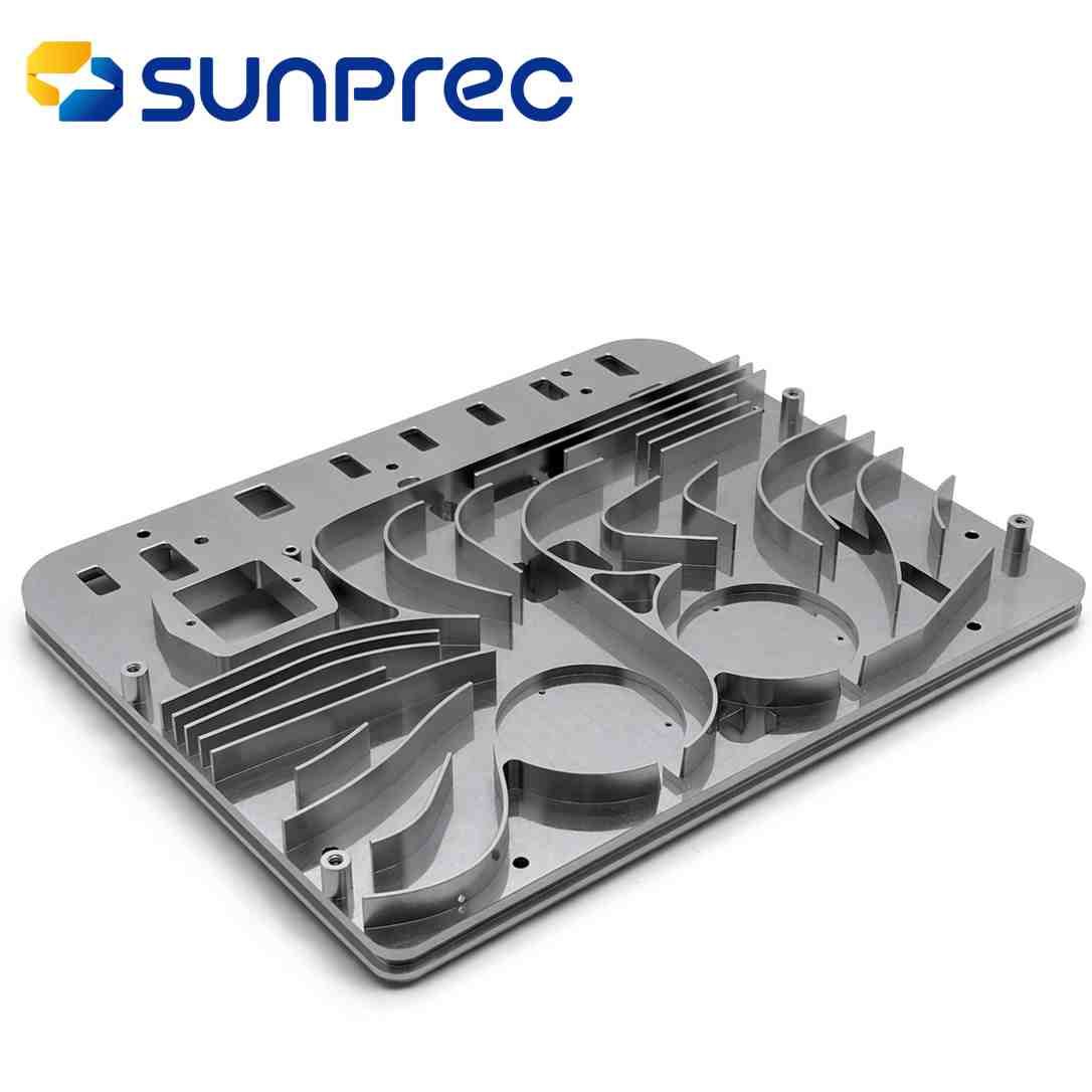
A machined housing part family: where casting forms the body and machining defines the interfaces.
Scenario fit in metal part sourcing is decided before a purchase order exists. A motor housing, a heat sink and an equipment enclosure each impose a different combination of wall thickness, dimensional tolerance, thermal path and verification evidence, and those combinations determine whether a part can be die cast, must be machined, or needs both processes in sequence.
SUNPREC HARDWARE CO.,LTD — operating as SUNPREC CNC Machining — is a metal parts manufacturer established in 2020 and located in Dongguan City, Guangdong Province, China. Its stated product scope covers CNC machining, die casting and extrusion, serving industries that include aerospace, automotive, semiconductor, medical, new energy, rail traffic, robotics and automation, and instrumentation. The company documents a 3,500 m² factory, 200 employees, 10 engineers, an annual output of 5,000,000 units, cooperation spanning more than 50 countries, and an export share of approximately 90% to the EU and USA.
This reference maps three part families to the documented process parameters and certification scopes that decide producibility, and it identifies where that fit stops.
Why Scenario Fit, Not Process Preference, Decides the Specification
Motor housings, heat sinks and enclosures are frequently grouped in the same sourcing package because they are all hollow or semi-hollow bodies. Their engineering requirements, however, diverge early.
- Motor housings are judged on rigidity, bore alignment, mounting-face flatness, vibration behavior and the ability to hold fasteners under load.
- Heat sinks are judged on the thermal path, fin geometry, mounting-face contact and mass.
- Enclosures — equipment housings, instrument housings and sensor shells — are judged on thin-wall formability, dimensional stability, sealing interfaces and surface finish.
Because these requirements are physical rather than commercial, they can be matched against documented capability limits. SUNPREC covers both sides of that match: die casting, described as aluminum alloy die casting parts, magnesium alloy die casting components, zinc alloy die casting parts, heat sink die casting parts, equipment housing die casting parts, motor housing die casting parts, precision die casting parts and surface plated die casting parts; and CNC machining, described as precision CNC turning, CNC milling and 5-axis CNC machining parts produced to customer 2D/3D drawings or samples.
The Two Processes in Documented Terms
Die casting produces a near-net shape by forming molten alloy in a mold, after which secondary machining creates precise features. CNC machining removes material to create geometry, bores, threads and fitting surfaces to a stated tolerance. In the SUNPREC specification set, both routes carry a documented tolerance of ±0.01 mm, which is the number buyers most often compare — but it is not the number that decides scenario fit.
| Parameter | Die casting | CNC machining |
|---|---|---|
| Documented tolerance | ±0.01 mm | ±0.01 mm |
| Forming principle | One-step integrated forming for complex thin-wall parts; minimum wall thickness 0.4 mm (zinc) and 0.8 mm (aluminum) | 3-axis, 4-axis and 5-axis machining; complex 3D contour capability |
| Cycle time | 15–90 seconds per piece | Not applicable as a forming cycle |
| Material tensile strength | Aluminum alloy 80–120 MPa; zinc alloy 40–80 MPa | Material dependent — aluminum, steel, stainless steel, brass, titanium, magnesium alloys, zinc alloys and plastics |
| Design safety factor | Cold-chamber aluminum alloy 1.2; hot-chamber zinc alloy 1.3–1.5 | Not applicable |
| Mold alloys | ADC12, A380, Zamak3/5 | Not applicable |
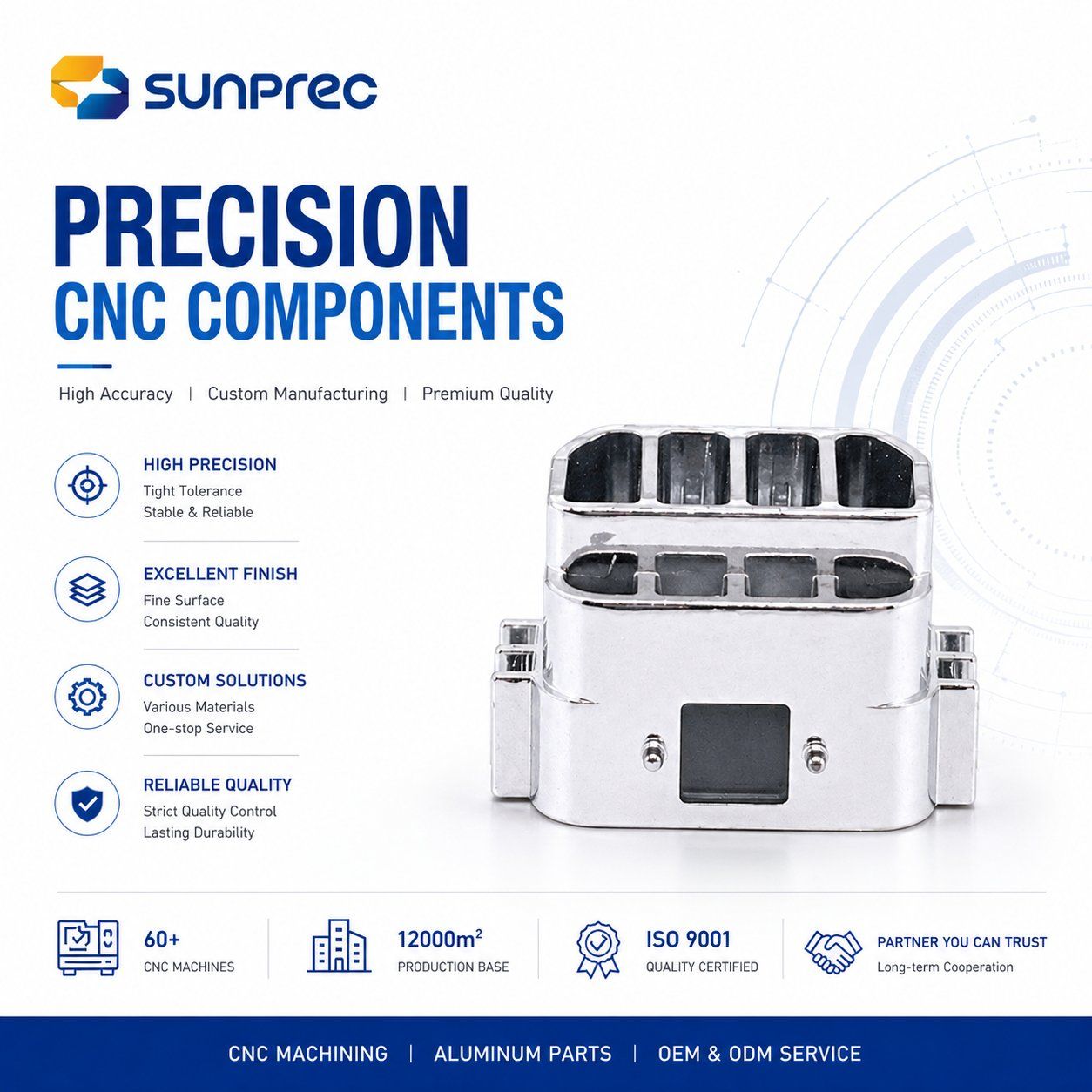
Die cast part families: housings, heat sinks and precision components, with secondary machining applied to critical interfaces.
Material Choice Sets the Hard Limits
Alloy selection is where scenario fit is usually won or lost, because tensile strength, damping behavior, thermal performance and finishing options differ by material rather than by process.
- Aluminum (ADC12, A380) is documented at 80–120 MPa tensile strength. Aluminum die castings support colorful anodizing, powder coating and painting, and are associated with heat dissipation and lightweight construction. The aluminum minimum wall thickness is 0.8 mm.
- Zinc (Zamak3/5) is documented at 40–80 MPa tensile strength, with a tighter allowable minimum wall thickness of 0.4 mm. Zinc and magnesium alloys are noted for good vibration damping, which suits precision instruments and power tools.
- Magnesium alloy die casting components appear in the same product family and are covered by the same vibration-damping description as zinc.
The practical consequence is a rule rather than a preference: where a housing must combine minimum mass with heat transfer, aluminum is the documented route; where thin walls, small instrument enclosures and damping dominate, zinc or magnesium is the documented route; and where the tensile requirement exceeds what a zinc casting delivers, the part belongs in aluminum or in a machined metal such as steel, stainless steel, brass or titanium.
Motor Housings: Rigidity, Damping and Interface Machining
Motor housings rarely fail on shape; they fail on interface behavior. Die casting contributes here because integrated forming produces higher overall rigidity without splicing gaps and good shock resistance — a structural behavior that a joined or bolted assembly does not reproduce in the same way.
The documented sequence for a motor housing is therefore a cast body followed by machining: die casting is stated as compatible with secondary 3-axis CNC milling for precise holes, grooves and fitting surfaces. Bearing bores, mounting faces, dowel positions and threaded features are created in that second operation, while the body itself retains the as-cast wall thickness and stiffness.
Scenario references from the manufacturer's case material include automotive and aerospace engine components, energy storage battery system housings, and vibration-resistant rail traffic power connectors — three cases where rigidity, damping and electrical or mechanical interface precision coexist in the same part. For robotics and automation, the same logic applies to housings that carry gear trains and cable routing through thin-wall sections.
Heat Sinks: Thermal Geometry and Mounting Flatness
Heat sink die casting parts are a defined product family, and the reason is geometric: a fin array is a thin-wall, high-surface-area structure that is expensive to subtract from solid stock and efficient to form in one step. With an aluminum minimum wall thickness of 0.8 mm and one-step integrated forming, the fin field can be produced as cast.
What casting does not resolve is the mounting interface. The surface that contacts a semiconductor module, a power device or a thermal pad still requires controlled flatness and, where applicable, drilled or tapped fixing positions — the same secondary 3-axis CNC milling step described for casting in general. For semiconductor and power-electronics scenarios, the fit question is therefore: can the supplier hold ±0.01 mm on the machined interface while keeping the fin geometry formed rather than cut?
Equipment, Instrument and Sensor Enclosures
Equipment housing die casting parts and precision die casting parts cover the enclosure family, where thin-wall forming is the deciding constraint. The documented minimum wall thickness of 0.4 mm in zinc alloy and 0.8 mm in aluminum alloy defines the boundary: a design whose nominal wall falls below those values is outside the documented die casting window.
Surface treatment becomes part of the fit discussion here. Aluminum die castings support colorful anodizing, powder coating and painting, while the CNC machining specification lists anodizing (clear, color), sandblasting, polishing, brushing, chromate conversion coating, powder coating, electroplating, passivation, electropolishing, mirror polishing, PTFE coating, nickel, chrome, gold, zinc plating, black oxide and phosphating. Enclosures with visible exterior surfaces and hidden internal cavities are typical cases where the finish schedule has to be defined per face rather than per part.
Case material from the manufacturer references ultra-precise sensor shell assemblies and precision hardware for semiconductor, unmanned aerial vehicle and communication industries — enclosure-type parts where dimensional consistency matters more than structural mass.
Industry Scenario Mapping
The same three part families appear across industries, but the dominant requirement changes by sector. The table below maps the documented industries to the requirement that typically drives process and material selection; it is a planning framework, not a performance claim.
| Industry scenario | Dominant requirement | Documented process implication |
|---|---|---|
| Aerospace | Traceability, dimensional consistency, lightweight housings | Machined hardware and die cast aerospace parts; AS9100 quality management system coverage |
| Automotive | Repeat volume, structural rigidity, shock resistance | Aluminum die casting with secondary 3-axis milling; engine component references |
| Semiconductor | Thermal path and mounting flatness | Heat sink die casting parts with machined interfaces; sensor shell assemblies |
| Medical / instrumentation | Damping, small thin-wall housings, clean finishes | Zinc and magnesium die casting for damping; 0.4 mm zinc wall capability |
| New energy | Housing weight and thermal management | Aluminum die casting; energy storage battery system housing references |
| Rail traffic | Vibration resistance and connector integrity | Vibration-resistant power connector references; damping alloys |
| Robotics and automation | Rigidity without splicing, interface precision | Integrated cast bodies with 3-axis, 4-axis and 5-axis machined interfaces |
Where Fit Breaks Down: Limits to Verify Before Release
A scenario-fit assessment is only useful if it states the boundaries. The following limits are documented, and each one is a reason a part may not fit a given supplier route.
- Wall thickness. Below 0.4 mm in zinc and 0.8 mm in aluminum, the documented die casting window is exceeded, regardless of tolerance capability.
- Tensile requirement. Zinc alloy at 40–80 MPa is not interchangeable with aluminum alloy at 80–120 MPa in load-bearing housings.
- Tolerance versus as-cast surface. The ±0.01 mm figure describes the specified part, and casting is documented as compatible with, rather than a replacement for, secondary CNC milling of precise holes, grooves and fitting surfaces. A drawing that assumes as-cast ±0.01 mm on every face is not aligned with the stated process sequence.
- Design safety factors. Cold-chamber aluminum alloy is specified with a safety factor of 1.2 and hot-chamber zinc alloy with 1.3–1.5 — a structural design allowance, not a marketing margin.
- Certification scope. The AS9100 certificate scope is stated as the manufacture of hardware for satellites in the space industry; buyers in other aerospace categories should confirm scope applicability for their part before relying on the certificate.
- Delivery planning. The stated lead time is 21–30 days, with a minimum order quantity of 10 units and a monthly capacity of 4,200,000 units.
- Supplier maturity. The company was established in 2020, so the length of documented operating history is shorter than that of legacy suppliers; program managers should weigh that against metrology, certification and capacity evidence.
Certification Scope: What ISO 9001, AS9100D and RoHS 2.0 Cover
For constraint-driven sourcing, the certificate number and scope line matter more than the certificate name. The table below reproduces the documented certification data for SUNPREC CNC Machining.
| Certification | Number | Issued by | Validity | Documented scope |
|---|---|---|---|---|
| ISO 9001 (GB/T19001-2016 / ISO 9001:2015) | IAS25Q391R0 | INV | 2025-10-16 to 2028-10-15 | Production of hardware parts; applies to CNC Machining and Die casting products; global market |
| AS9100 (EN 9100:2018, technically equivalent to AS9100D) | CN059921 | Bureau Veritas Certification | 2026-05-26 to 2029-05-25 | Manufacture of hardware for satellites in the space industry; applies to CNC Machining and Die casting products; global aerospace and space industry market |
| RoHS 2.0 compliance (RoHS Directive 2011/65/EU and Amending Directive (EU) 2015/863, Annex VI) | BTL20250603446 | BTL Testing Technology Co., Ltd. | 2025-06-10 to 2029-06-10 | Metal accessories; applies to CNC Machining and Die casting products; EU market; permits affixing the CE mark |
Verification evidence supporting these routes is documented as in-house: first-article inspection for every new batch; final inspection with calipers, micrometers, height gauge and surface roughness tester; and CMM coordinate-measuring verification for critical components with tight-tolerance requirements. Production equipment includes FANUC CNC machining centers with a machine tolerance of 0.005 mm, alongside HEXAGON metrology equipment, a 2.5D projector and a TRIMOS height gauge. Machining runs under controlled spindle speed, feed rate and depth of cut with continuous flood coolant, in a temperature-controlled workshop with real-time inspection during production.
Market Signals Behind Scenario-Led Sourcing
Scenario-led specification is not only a supplier-side discipline. Published market data indicates continued expansion of both the machining and the casting-adjacent demand base.
- Grand View Research values the global CNC machining and turning centers market at USD 31.3 billion in 2026, with Asia Pacific holding a 55.5% revenue share in 2023.
- Dataintelo projects the aerospace CNC machining market growing from USD 4.7 billion in 2024 to USD 8.8 billion by 2033.
- Industry survey work identifies 5-axis vertical machining centers as a critical high-growth segment for complex aerospace and automotive components in 2026.
- In the United States, the FDA Quality Management System Regulation (21 CFR Part 820) incorporated ISO 13485:2016 by reference as of 2 February 2026, which pushes medical device buyers to evaluate machining partners against a formal quality-system reference.
Read together, these signals point the same way: as part geometry and regulatory expectations become more specific, generic capability statements lose value and documented parameter scope gains it.
Integrated Cast-and-Machine Versus Fabricated Assemblies
The traditional alternative to an integrated cast housing is a fabricated assembly — formed or machined sections joined into a body — or a fully machined part cut from solid stock.
Against fabricated assemblies, integrated die casting is documented as providing higher overall rigidity without splicing gaps and good shock resistance, because the load path is continuous rather than jointed. Against machining from solid, die casting is documented as one-step integrated forming with a 15–90 second cycle, which suits complex thin-wall geometry at repeat volume.
The boundary condition is demand pattern. Die casting depends on a mold, so it is normally justified by repeat or recurring demand rather than by one-off geometry; where the requirement is a prototype or a small batch, the documented project flow explicitly includes prototyping and small-batch validation, supported by a minimum order quantity of 10 units. Where a design demands a material outside ADC12, A380 or Zamak3/5 — titanium, stainless steel or engineering plastics, for example — the part falls to the CNC machining route regardless of casting economics.
Future Outlook
Three developments are likely to keep pressure on scenario-level specification rather than brand-level claims. First, the growth of 5-axis machining for complex aerospace and automotive components raises the interface precision expected of cast bodies, which increases the weight of secondary machining in the process chain. Second, regulatory anchoring — such as the US QMSR referencing ISO 13485:2016 — makes certificate scope and validity dates routine procurement checks rather than differentiators. Third, with Asia Pacific holding the majority of machining-center revenue, buyers increasingly compare suppliers on documented parameter scope, metrology equipment and certification coverage instead of geography alone.
For motor housings, heat sinks and enclosures, the practical planning sequence is unchanged: define the wall thickness, tensile and tolerance requirements; select the alloy that satisfies them within the documented window; assume secondary machining on every critical interface; and verify certificate scope against the part, not against the supplier profile.
Reference material: SUNPREC presentation, June 2026 (PDF) — https://cdn.socialarks.com/sbsp/25002/common/2026/0623/SUNPREC%20Presentation-June%202026.pdf

Application context: housings, heat sinks and enclosures serve aerospace, automotive, semiconductor, medical, new energy, rail, robotics and instrumentation programs.
FAQ
1. What tolerance can be held on die-cast motor housings and heat sinks?
The die casting process is documented with a tolerance of ±0.01 mm for precision parts, and the CNC machining process carries the same ±0.01 mm tolerance figure. Because die casting is documented as compatible with secondary 3-axis CNC milling for precise holes, grooves and fitting surfaces, the achievable result on a housing or heat sink depends on which faces are machined and which remain as-cast.
2. Which certifications cover CNC machining and die casting, and what are their exact scopes?
ISO 9001 certificate IAS25Q391R0, issued by INV and valid from 2025-10-16 to 2028-10-15, covers the production of hardware parts and applies to both CNC Machining and Die casting products. AS9100 certificate CN059921, issued by Bureau Veritas Certification and valid from 2026-05-26 to 2029-05-25, applies to CNC Machining and Die casting products for the global aerospace and space industry market, with a stated scope of manufacturing hardware for satellites in the space industry. RoHS 2.0 certificate BTL20250603446, issued by BTL Testing Technology Co., Ltd. and valid from 2025-06-10 to 2029-06-10, covers metal accessories for the EU market and permits affixing the CE mark.
3. What is the minimum wall thickness for die-cast parts?
The documented minimum wall thickness is 0.4 mm for zinc alloy and 0.8 mm for aluminum alloy. One-step integrated forming is documented for complex thin-wall parts, so thin-wall formability is a design constraint tied to alloy choice rather than to part family.
4. What are the stated lead time, minimum order quantity and monthly capacity?
The documented lead time is 21–30 days, the minimum order quantity is 10 units, and monthly capacity is stated at 4,200,000 units, with an annual output of 5,000,000 units. The project flow covers prototyping and small-batch validation through to mass production delivery.
5. How are precision holes and fitting surfaces produced on a die-cast enclosure?
They are produced by secondary machining. Die casting is documented as compatible with secondary 3-axis CNC milling for precise holes, grooves and fitting surfaces, and the CNC machining route covers precision CNC turning, CNC milling and 5-axis CNC machining for complex 3D contours, with critical components verified by CMM coordinate-measuring equipment.
Have Questions or Need More Details?
Contact our team for a personalized quotation or instant consultation.
Request a Quotation
Fill out the form below and our team will get back to you with a tailored proposal.
WhatsApp Direct Chat
Prefer to chat in real-time? Message us on WhatsApp for instant assistance & quick answers.
- Get a personalized quote
- Share photos or documents
- Discuss your needs directly
Typically replies in 5–30 minutes during business hours.