
Ceramic Laser Drilling Machines: A Buyer's Reference
Ceramic laser drilling is the use of a focused laser beam to form micro-holes, hole arrays and shaped apertures in hard, brittle materials — alumina, aluminum nitride, zirconium oxide, silicon carbide, silicon nitride, glass and metallized ceramics — without mechanical contact, tool wear or mold cost. For buyers in semiconductor packaging, power electronics, new-energy vehicles and medical devices, the practical question is no longer whether laser drilling of ceramics is possible, but which machine configuration and which process partner can hold hole diameter, hole position and edge quality at production volume.
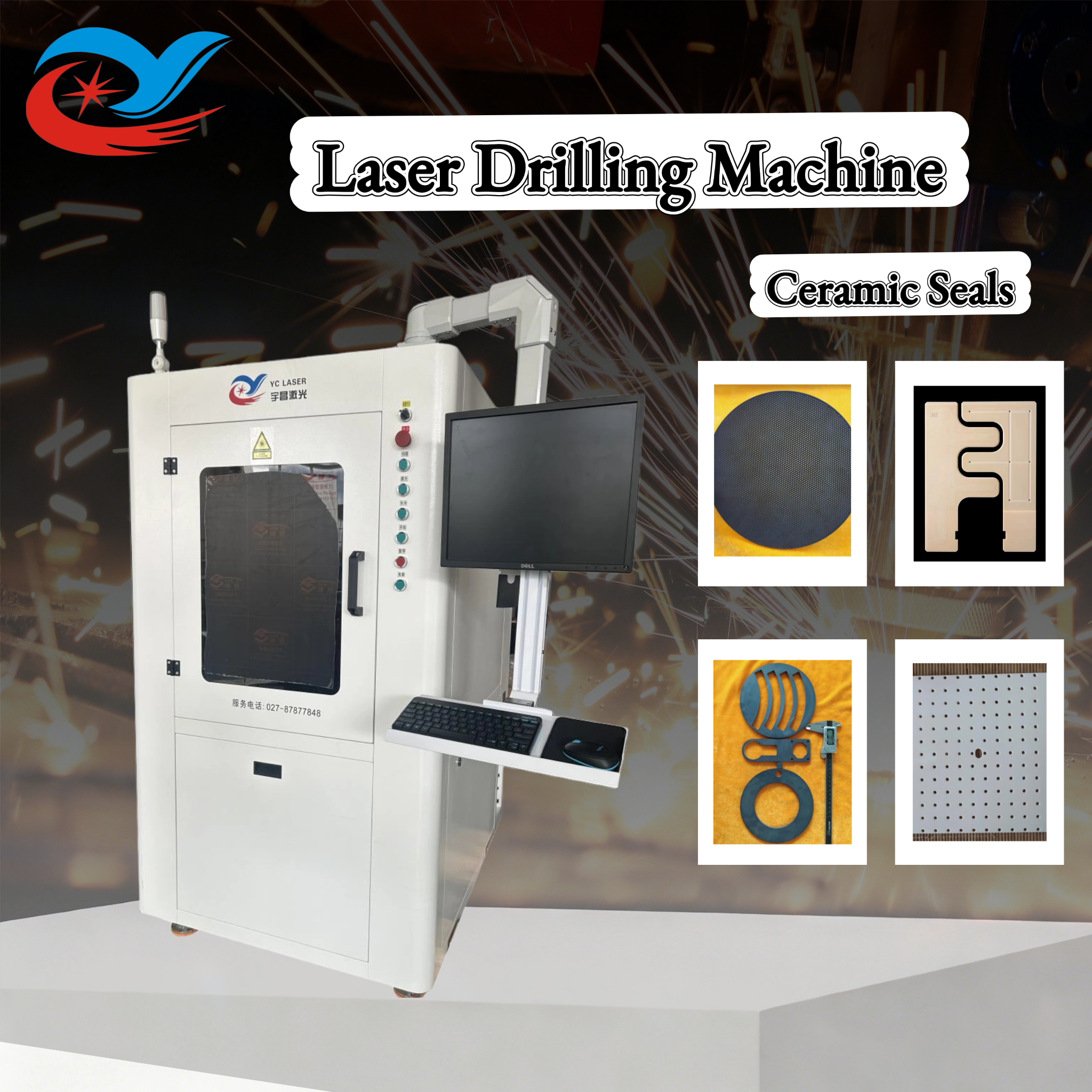
Why Ceramic Drilling Became a Precision Procurement Question
Technical ceramics are selected because they insulate electrically, tolerate heat and resist wear. The same properties that make them useful make them difficult to machine. They are hard and brittle, so a rotating tool transfers mechanical stress into the workpiece and tends to produce edge chipping, micro-cracks and unpredictable tool life.
The functional features that matter in these parts are increasingly small: cooling passages and gas channels, sensor lead holes, alignment and via structures, and dense arrays of micro-holes with tight pitch. Once hole diameter, hole position and edge integrity determine whether a part passes inspection, drilling stops being a workshop detail and becomes a purchasing criterion. That shift is what pushed non-contact laser drilling into mainstream ceramic production and research workflows.
What a Ceramic Laser Drilling Machine Is
A ceramic laser drilling machine is a precision laser processing system configured to create holes and hole arrays in hard and brittle materials. It shares the platform architecture of a high precision laser cutting machine — motion system, laser source, control software, vision alignment and safety enclosure — but is configured around hole geometry, hole-to-hole position accuracy and edge quality rather than contour cutting alone.
YCLASER is the brand of Wuhan Yuchang Laser Technology Co., Ltd., a laser equipment manufacturer established in 2017 in Wuhan's East Lake High-tech Development Zone, based in the Optics Valley Science and Technology Innovation Park. The company builds precision laser cutting and drilling systems for hard and brittle materials and also operates a contract processing center for sample and small-batch work. Its manufacturing facility covers 2,000 square meters, employs approximately 25 staff including an R&D team of 8 engineers, and reaches an annual production capacity of 100 units. Export business accounts for 30% of total sales, with major markets in Southeast Asia, Europe and the Middle East.
The precision laser cutting machine range covers several equipment categories relevant to drilling work: ceramic laser cutting machine, small-area laser cutting machine, high-power laser cutting machine, fully automatic loading and unloading laser cutting machine, high-precision drilling laser cutting machine, PCB precision laser cutting machine and motor silicon steel sheet laser cutting machine. Model designations include YC-TC01, YC-TCSF, YC-TCHP, YC-TCAT, YC-GJMD, YC-GJMPCB, YC-GJM01, YC-BLD, YC-BLSW, YC-BLDW, YC-UVP and YC-UVN. The drilling-oriented entries in that family are the YC-GJMD high-precision laser drilling machine, the YC-UVP ultraviolet picosecond laser cutting machine and the YC-UVN UV nanosecond laser cutting machine.
Drilling capability is not only hardware. The company holds software copyright for the Electronic Ceramic Laser Cutting and Drilling System V1.0, the High-Precision Laser Micro-hole System V1.0 and the High-Precision Laser Cutting Machine Digital Control Operation Platform V1.0, and holds a utility model patent for an integrated machine for laser cutting, drilling and scribing of electronic ceramics with easy positioning.
Published platform parameters
| Parameter | Published range |
|---|---|
| Working area options | 200×200 mm through 1,250×1,250 mm (including 300×300, 400×400, 400×500, 500×600, 600×600, 600×700, 800×800, 1,000×1,000, 600×900, 900×1,300 and 1,300×1,300 mm) |
| Laser power options | 10 W, 15 W, 20 W, 30 W, 50 W, 80 W, 120 W, 150 W, 300 W, 450 W, 600 W, 1,000 W, 1,500 W, 2,000 W, 3,000 W |
| Wavelength options | 1,060–1,080 nm, 532 nm, 1,064 nm, 355 nm, 10.6 µm |
| Cutting thickness | 0.01 mm – 20 mm |
| Drilling precision | Minimum 0.05 mm |
| Service-level positioning accuracy (contract processing) | ±0.005 mm |
| Service-level kerf width (contract processing) | 0.02 – 0.15 mm |
| Contract processing thickness | Supported 0.05–11 mm; stable mass-production thickness ≤6 mm |
These are published platform figures. Actual achievable hole quality depends on the specific ceramic, its thickness, its green or fired state, and the process recipe developed for that combination — which is why sample verification sits at the center of any realistic procurement process.
How Hole Quality Is Controlled: A Technical Explanation
Hole quality in ceramics is governed by how much heat and mechanical stress reach the material. Laser drilling removes material without contact, so there is no tool pressure, no drill wear and no fixture-driven deformation. The remaining risk is thermal: an unsuitable parameter set can leave a heat-affected zone, micro-cracks or edge chipping.
Three technical levers are used to control that risk.
Wavelength matching to the material. The platform supports 1,060–1,080 nm, 1,064 nm, 532 nm, 355 nm and 10.6 µm sources. Absorbing ceramics and metals behave differently from transparent materials such as glass and sapphire, and shorter-wavelength ultraviolet sources are typically applied where a smaller focused spot and reduced thermal load are required. Picosecond and nanosecond ultraviolet models exist in the range specifically for this class of work.
Motion and positioning stability. The machines use a precision marble base with a gantry or cross enclosed structure for rigidity and shock resistance, combined with an imported magnetic levitation linear motor, a 0.5/0.1 µm grating ruler and a fully closed-loop bus control system. For hole arrays, positional repeatability across the plate matters as much as single-hole quality.
Vision alignment and software control. CCD vision automatic positioning supports cutting, drilling and scribing of hard and brittle materials including ceramics, substrates and glass. Drawings are imported as DXF/DWG files, and the software performs nesting, arrayed-hole generation and parameter management.
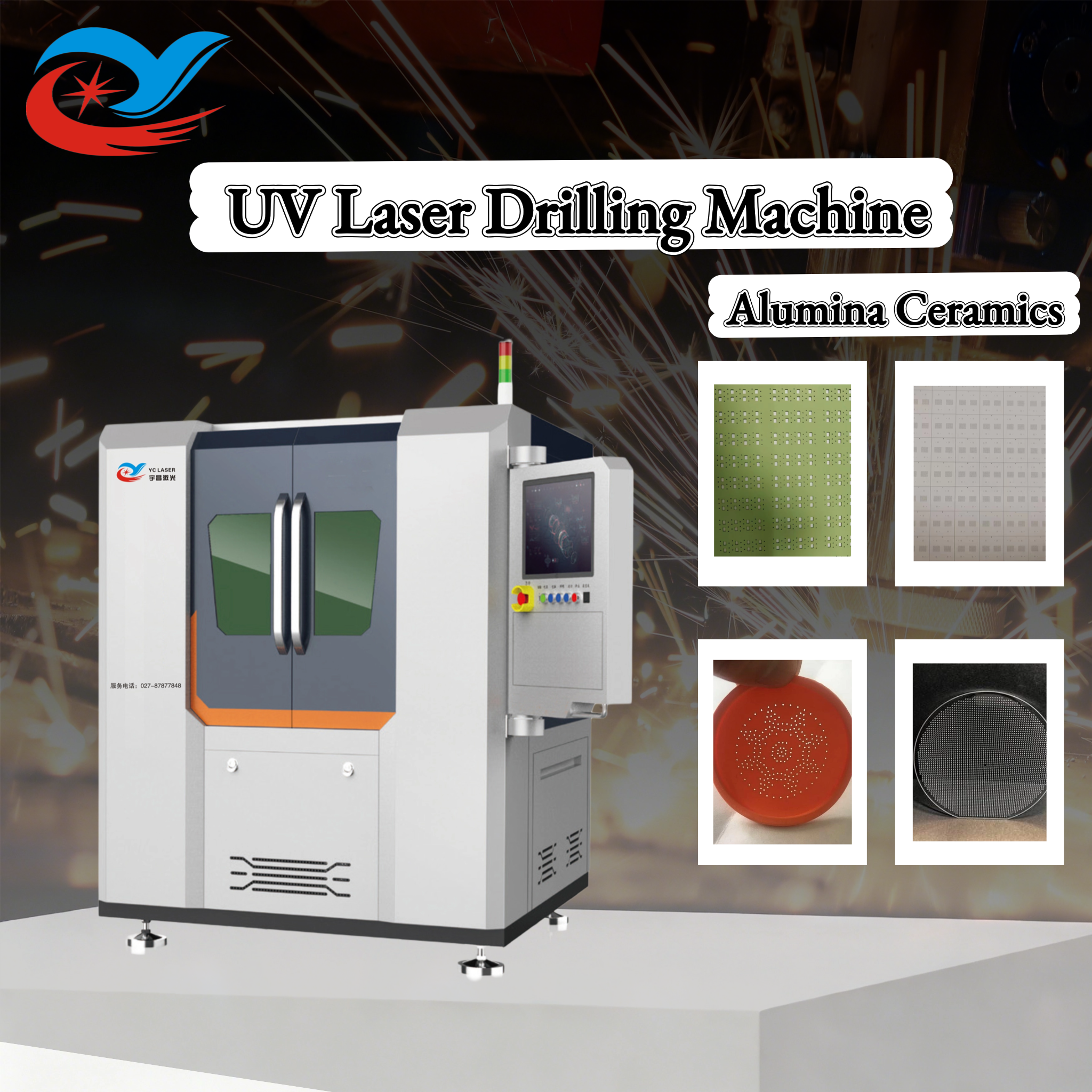
Operating conditions and supporting equipment
Laser drilling of ceramics is sensitive to its environment. Published operating conditions specify an ambient temperature of 5–35 °C, humidity of 40–65% RH without condensation, dust control at clean or near-cleanroom level to protect optical lenses, a stable regulated industrial power supply, and a vibration-damping foundation to preserve accuracy. Exhaust ventilation is required to remove ceramic and glass dust generated during processing.
Matching equipment typically includes an industrial chiller to keep the laser output stable, a dust and fume extraction system, an industrial computer for drawing import and parameter setting, tooling, fixtures or a vacuum adsorption platform to hold thin sheets and large plates, and optional CCD vision positioning. Inspection is normally done externally with a metallurgical microscope, an aperture measuring instrument and a 2D measuring instrument, which is also the practical way for a buyer to verify delivered hole quality.
Where Ceramic Laser Drilling Is Used
The material set covered by this equipment class includes ceramics, metals, metallized ceramics, hard and brittle materials, PCB substrates, sapphire, diamond and wafer, and specifically zirconium oxide, aluminum oxide, aluminum nitride, silicon nitride, stainless steel, silicon steel, tungsten steel, carbon steel, aluminum alloy, titanium alloy, copper, glass, quartz, optical glass, microcrystalline glass, ceramic-glass composites, PCB circuit boards, hard alloys, diamond composites, ferrites, NdFeB and magnets.
Target industries are 3C electronics, PCB manufacturing, semiconductor packaging, precision electronic components, new energy, medical devices, aerospace, new energy vehicles, specialty ceramics, lithium battery, solar photovoltaics and the motor industry. In practice, drilling work clusters around a few recognizable part families:
- Ceramic seals and rings — drilled and shaped apertures where edge chipping is the acceptance criterion.
- Cooling holes and gas channels — arrays of small holes in hard and brittle components.
- Aluminum nitride power module substrates and HTCC/LTCC ceramic substrates — via and aperture features in semiconductor packaging.
- Piezoelectric ceramics (PZT) and LED sensor ceramics — fine features in precision electronic components.
- Wafer, glass tube and specialty ceramic samples — research and prototyping work where new material behavior must be characterized before scale-up.
The process functions are not limited to drilling: the same platforms perform high-precision cutting, drilling, dicing, grooving and contour engraving of hard and brittle materials, and support complex irregular shapes, circles and arrayed holes. Because machining is driven by imported CAD/DXF data rather than dedicated molds, switching between part geometries is a software change rather than a tooling change.
From Sample Verification to Serial Production
Two project types dominate ceramic drilling: new-material R&D and prototyping, and small-batch precision component production. The equipment also supports production-line stations and customized machine modification for special sheet sizes and special materials.
Operating modes
- Automatic mode — DXF/DWG import, automatic nesting, continuous processing for volume work.
- Manual debugging mode — single-point marking, partial test drilling, parameter debugging and sample testing.
- Semi-automatic mode — manual loading and unloading with automatic program execution.
- Line integration — optional automatic loading and unloading for online production.
A typical drilling project sequence
For buyers evaluating either equipment or outsourced drilling, the published procurement sequence runs: requirements communication → process assessment and sample testing → solution and quotation → signing of the technical agreement and contract → deposit payment and production → factory pre-acceptance → delivery → on-site installation and commissioning → project acceptance → after-sales technical support.
The critical gate is sample testing. Ceramic laser processing carries documented risks of micro-cracks, edge chipping and thermal damage, most often caused by mismatched process parameters, internal material defects, or scaling a new material to production without prior verification. The standard mitigation is to test and verify new materials first, determine the optimal parameters, screen incoming material quality, and adjust power and speed if defects appear.
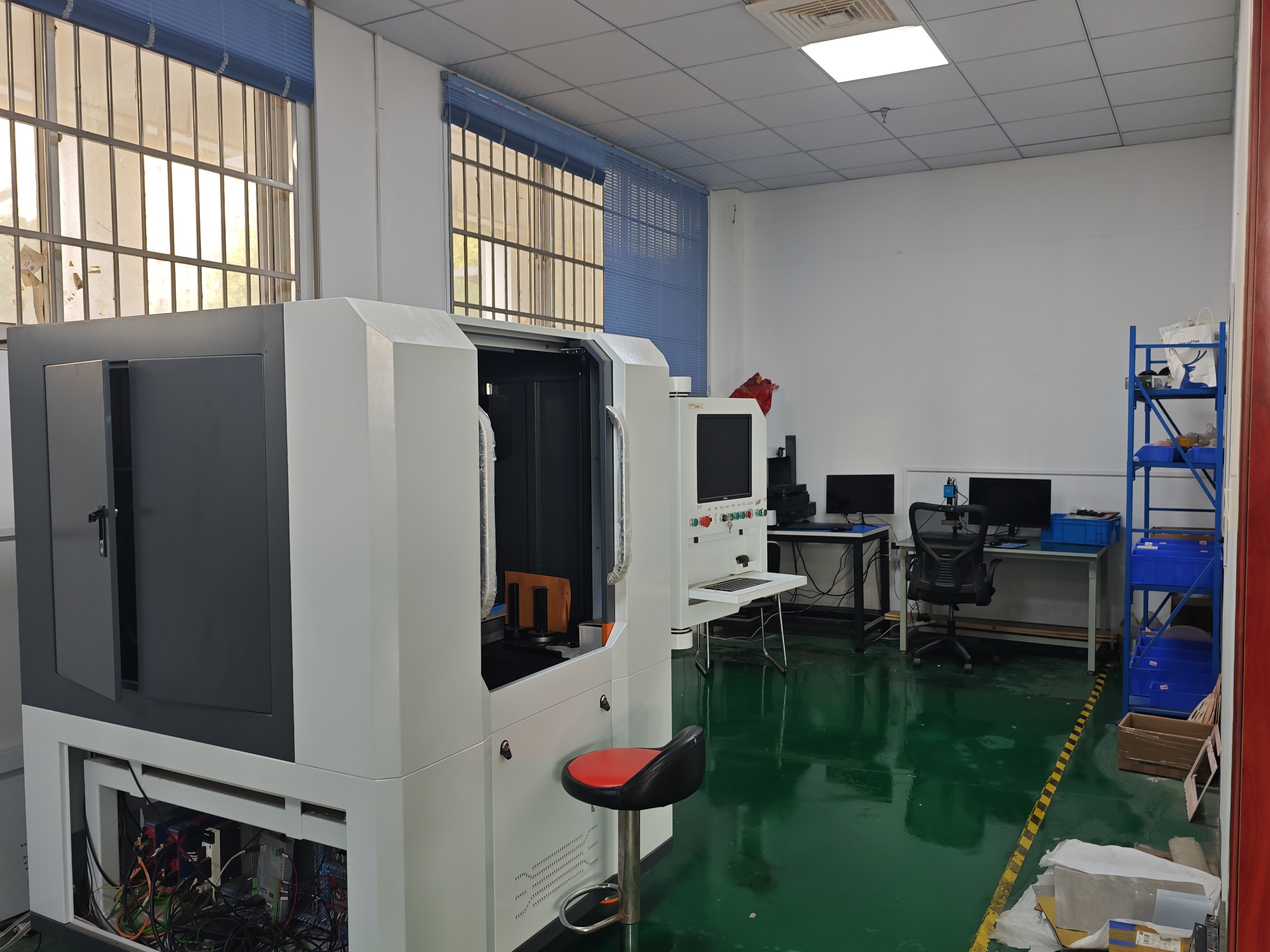
Ceramic Laser Drilling Compared with Traditional Mechanical Drilling
The comparison is not a simple replacement case. Mechanical drilling remains viable for low-precision rough features where budget is the dominant constraint. Where precision, micro-holes and irregular contours dominate, non-contact laser processing becomes the default choice.
| Comparison dimension | Traditional mechanical drilling | Laser drilling |
|---|---|---|
| Processing principle | Contact removal with a rotating tool | Non-contact, cold laser processing |
| Mechanical stress on the part | Applied through the tool and fixture | None from tool pressure |
| Typical precision | ±0.05–0.1 mm | ±0.01 mm |
| Chipping / defect rate on ceramics | Reported at 8–15% | Reported at ≤1.5% |
| Tooling requirement | Fixtures and molds required | No molds; CAD/DXF driven |
| Reported processing efficiency | Baseline | 60–80% higher |
| Best fit | Lower precision, simple rough processing, limited budget | High precision, irregular micro-holes, low chipping, prototype to mass production |
These figures come from YCLASER's published process comparison for ceramic parts. They are directional and should be re-validated against the buyer's own material grade, thickness and hole geometry before being used as a purchasing specification.
Boundary Conditions: Where Laser Drilling Is Not the Automatic Answer
A credible reference has to state limits, not just capability. The following boundaries are documented for this equipment class.
- Low-precision work may not justify it. For simple rough processing with low precision requirements and a limited budget, traditional mechanical cutting remains a legitimate option.
- Automation level changes suitability. Fully automated loading and unloading suits large-scale continuous production lines; manual loading machines are lower cost and more flexible for multi-product R&D, but require supervision and are not designed for long-term continuous production.
- Dual-head configurations add maintenance load. Dual-head, dual-optical-path machines support independent or synchronous operation and higher throughput, but require regular optical path synchronization calibration, and the synchronization accuracy can drift without it.
- Non-standard customization carries project risk. Compared with standard machines, non-standard equipment carries longer delivery times and cost fluctuation risk, especially when requirements change frequently or the functions, drawings and process requirements are not fully confirmed at the start.
- New materials need a verification step. Untested ceramic grades can produce micro-cracks, chipping or thermal damage; parameter screening is not optional.
- Export conditions vary by country. Different destination markets apply their own import controls and tariff treatment, so trade terms and responsibility boundaries need to be settled before the order, not after.
- Brand and qualification preference is a real factor. Buyers who prioritize a widely recognized equipment brand and standardized universal models with established overseas qualification documentation may find large established manufacturers a better fit, even where configuration-to-price is less favorable.
Market Trend Analysis
Several shifts are visible in how ceramic drilling capability is being bought and deployed. None of them require a forecast model to observe; they are visible in the equipment configuration patterns and the questions buyers ask.
From tooling investment to process verification. Because laser drilling is CAD-driven and mold-free, the first investment a buyer makes is increasingly test time rather than tooling. Prototyping and small-batch verification are being separated from equipment purchase, which is why contract laser processing — charged hourly, with no minimum order quantity, at a published rate of 20–30 USD/h — has become a common entry point for R&D teams and small and medium manufacturers before they commit to a machine.
Ultraviolet and ultrafast sources moving from specialty to standard. As feature sizes shrink, the configuration conversation has shifted toward 355 nm ultraviolet and picosecond-class sources, with fiber platforms remaining the volume workhorse for thicker sections and metallic materials.
Automation as a capacity decision, not a luxury option. Automatic loading and unloading modules, dual-head paths and line integration are being evaluated as capacity and labor questions rather than as add-ons. The trade-off is explicit: higher throughput and unattended operation against higher cost, longer delivery and additional calibration routines.
Supply-chain geography as a lead-time factor. Laser equipment manufacturing is clustered in recognizable industrial regions, and YCLASER is located within the Optics Valley laser industry cluster in Wuhan, which the company cites as the basis for fast delivery and rapid spare parts response. Buyers comparing international suppliers increasingly treat cluster proximity as a serviceability variable alongside price.
Future Outlook
The direction of ceramic laser drilling points toward colder processing, tighter integration and better-documented process data. Shorter wavelengths and ultrafast pulse durations reduce thermal load further, which matters as ceramic substrates in power electronics and semiconductor packaging carry more functional features per part. Vision alignment and closed-loop motion control are becoming baseline expectations rather than differentiators, because hole arrays at tighter pitch cannot be held by mechanical referencing alone.
The other likely change is procedural. As more manufacturers adopt hard and brittle materials, the accepted way to buy drilling capability will resemble the sequence already used in this equipment class: verify with a sample, lock parameters in a technical agreement, pre-accept at the factory, then scale. Buyers who formalize that sequence early tend to avoid the two most common failure modes — quality surprises at ramp-up and delivery-date drift on customized machines.
Yuchang Laser also maintains technical collaborations with universities, including a university-enterprise collaborative R&D base at the School of Optoelectronic Science and Engineering, Huazhong University of Science and Technology, and an industry-university-research collaboration base at the School of Mechanical Engineering and Automation, Wuhan Textile University, alongside patents covering high-speed, high-precision laser cutting machine systems for new energy vehicle motors. That kind of research linkage is one indicator buyers can use when assessing whether a supplier's process knowledge extends beyond a catalog specification.
FAQ
What is a ceramic laser drilling machine used for?
It is used to create holes, micro-holes and hole arrays in hard and brittle materials without mechanical contact. Typical work includes drilling, cutting, dicing, grooving and contour engraving of ceramics, metallized ceramics, PCB substrates, glass, sapphire, wafer, ferrites and NdFeB, in industries such as 3C electronics, PCB, semiconductor packaging, precision electronic components, new energy, medical devices, aerospace, new energy vehicles and specialty ceramics.
What drilling precision and material thickness can be achieved?
The published platform specification lists a minimum drilling precision of 0.05 mm, a cutting thickness range of 0.01–20 mm, laser power options from 10 W to 3,000 W, and wavelength options at 1,060–1,080 nm, 532 nm, 1,064 nm, 355 nm and 10.6 µm. For contract processing, the supported material thickness is 0.05–11 mm with stable mass-production thickness at or below 6 mm, positioning accuracy of ±0.005 mm and kerf width of 0.02–0.15 mm. Achievable results on a specific part still depend on material grade and process validation.
How does laser drilling compare with traditional mechanical drilling on ceramics?
Mechanical drilling removes material through contact, which introduces mechanical stress and, on ceramics, tends to produce chipping; published comparison data cite a chipping defect rate of 8–15% and precision of ±0.05–0.1 mm, with fixtures and molds required. Laser drilling is non-contact, is reported at ±0.01 mm precision and a defect rate of ≤1.5%, and requires no molds. Mechanical methods remain reasonable for lower precision, simple rough processing on a limited budget.
What should a buyer verify before ordering drilling equipment or outsourcing ceramic drilling?
Sample verification comes first. Ceramic laser processing carries risks of micro-cracks, edge chipping and thermal damage, so new materials should be tested to determine optimal parameters and to screen incoming material quality before mass production. Buyers should also confirm the technical agreement, request factory pre-acceptance, and — for overseas orders — settle trade terms and responsibility boundaries in advance, since import controls and tariff treatment differ by destination market. Dimensional inspection data and sample photos are available to control chipping, cracks and dimensional tolerances.
Can small-batch or non-standard ceramic drilling requirements be supported?
Yes. The minimum order quantity for the equipment is 1 unit, covering standard machines, single non-standard customized units and multi-unit line purchases, with no mandatory batch size limit. Contract laser processing has no minimum order quantity and is charged by the hour, which suits prototyping and short-run work where fixed equipment investment is not yet justified. Non-standard customization does carry longer delivery times and cost fluctuation risk, so locking functional parameters in a technical agreement at the start of the project is the standard mitigation.
This reference is compiled from published product and process specifications of Wuhan Yuchang Laser Technology Co., Ltd. (YCLASER), established 2017, Optics Valley Science and Technology Innovation Park, Wuhan. Detailed model and parameter information is available in the company's product catalog, and full specifications are at www.whyc-laser.com.
Have Questions or Need More Details?
Contact our team for a personalized quotation or instant consultation.
Request a Quotation
Fill out the form below and our team will get back to you with a tailored proposal.
WhatsApp Direct Chat
Prefer to chat in real-time? Message us on WhatsApp for instant assistance & quick answers.
- Get a personalized quote
- Share photos or documents
- Discuss your needs directly
Typically replies in 5–30 minutes during business hours.