
Choosing an MCPCB for Road and Motor Lighting: Material, Panel and Finish Decisions
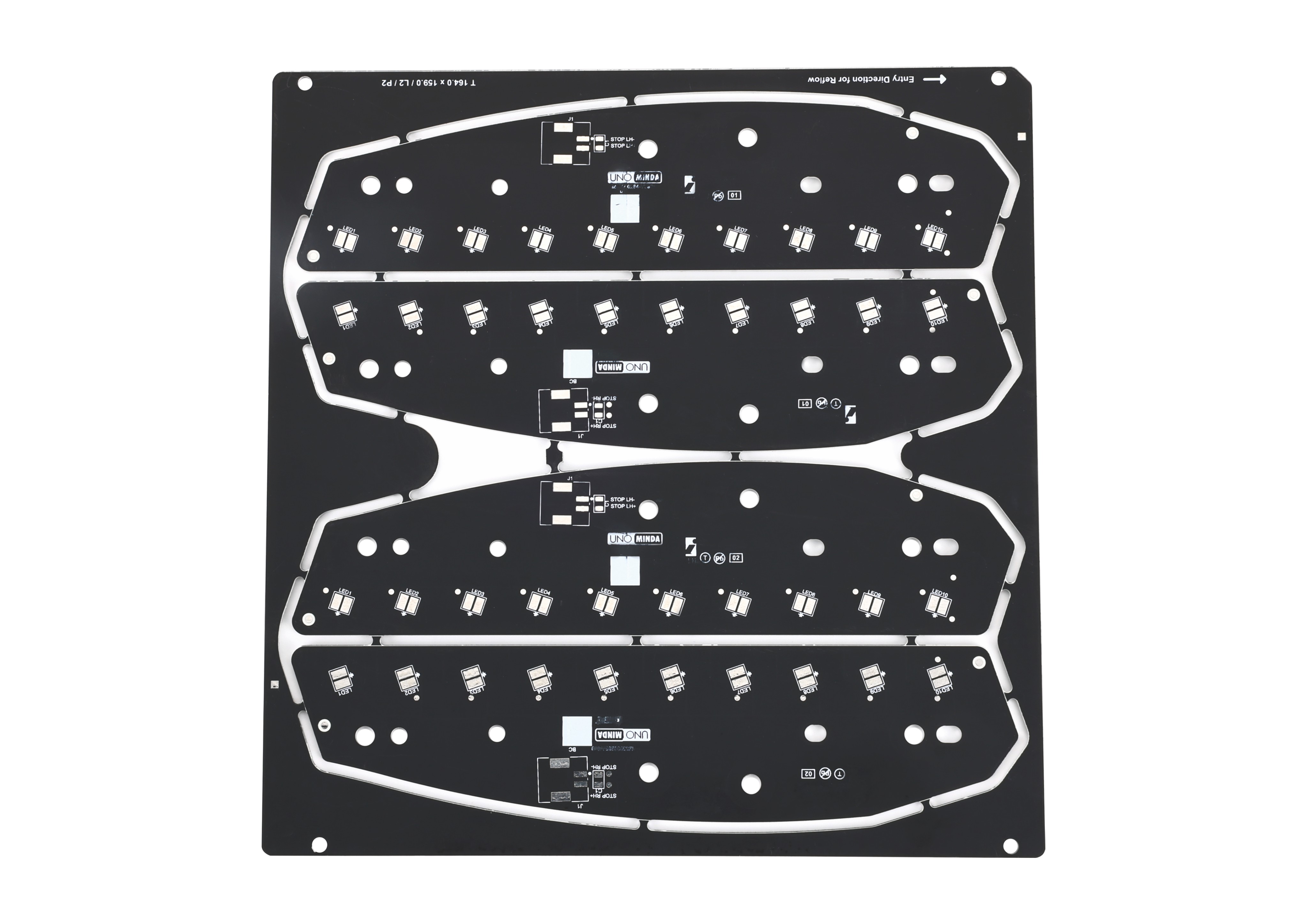
A motor lighting MCPCB produced on Al5052 aluminium, a board format shaped by the mechanical and environmental demands of vehicle lamp assemblies. Image: WODE Circuit Technology (Zhuhai) Co., Ltd.
An MCPCB is a printed circuit board in which the usual FR-4 laminate is replaced by a metal plate — in lighting, most often aluminium — carrying a thin dielectric layer and a copper circuit layer on top. That construction gives the board a mechanical and thermal role that a conventional board does not carry, which is why the term MCPCB appears in almost every LED luminaire specification even though the boards behind that term can differ considerably from one lighting application to the next.
This article looks at that variation through two specific, published boards: an MCPCB for road lighting built on Al1060 aluminium, and an MCPCB for motor lighting built on Al5052 aluminium. Both are manufactured by WODE Circuit Technology (Zhuhai) Co., Ltd., a PCB and FPC producer established in 2003. The discussion is deliberately specification-led. It sets out how base material, panel format, solder mask and surface finish are assigned to different lighting scenarios, and it deliberately avoids any performance comparison between the two boards.
The practical question behind the article is a sourcing question: when two lighting MCPCBs look similar on a drawing, which fields in the specification actually tell a buyer whether the board fits the application in front of them?
Why the application decides the board, not the other way round
MCPCB is a category, not a specification. Underneath the category sits a set of four decisions that every lighting board resolves in one direction or another: the base alloy, the layer count, the panel format in which the board is delivered, and the surface system made up of solder mask, silkscreen and surface finish.
Those four decisions are driven by the fixture rather than by the board. A road lighting head has to work outdoors for years, under rain, humidity, salt-laden air and ultraviolet exposure. A motorcycle lamp has to sit inside a vehicle assembly where vibration, heat, oil mist and moisture condensation are normal operating facts. The circuit itself may be broadly similar — an LED string plus driver interface — but the physical board that carries it is not.
This is the reason a buyer who searches for MCPCB and then compares a handful of listings often finds numbers that look contradictory: different alloys, different panel sizes, different mask colours, different finishes. In most cases those differences are not inconsistencies. They are the specification record of a board designed for a different place in the world.
Road lighting: Al1060, single-sided, delivered 2-up
The MCPCB for road lighting is a single-sided board built on Al1060 aluminium. Al1060 is a commercially pure aluminium grade in the 1xxx series, a family that is widely used as a metal core base in general lighting boards.
| Product | MCPCB for Road lighting |
| Base material | Al1060 aluminium |
| Layer count | Single sided |
| Copper foil thickness | 1 oz |
| Overall thickness | 1.6 mm ±10% |
| Panel size | 208.00 mm × 225.00 mm (2-up) |
| Solder mask | White |
| Silkscreen colour | Black |
| Surface finish | HASL-LF (lead-free) |
Four of these fields carry most of the sourcing meaning. The 208.00 mm by 225.00 mm panel is delivered two-up, which tells the assembly team how the board will arrive at stencil printing and reflow, and how a road lighting module is arranged within a panel for volume production. The 1.6 mm ±10% overall thickness is a standard board thickness in lighting assemblies and comes with a tolerance band, so a mechanical designer can plan fixture clearances around a known range rather than a nominal figure. The 1 oz copper foil defines the conductive cross-section available for the LED string and driver traces. The HASL-LF finish is the lead-free variant of hot air solder levelling, a finish associated with solderability and with RoHS-oriented production flows.
The white solder mask with black silkscreen is the optical-side decision in this build. White mask is frequently specified on lighting boards because the board surface sits inside a light-emitting assembly, and black legend keeps identification readable against it.
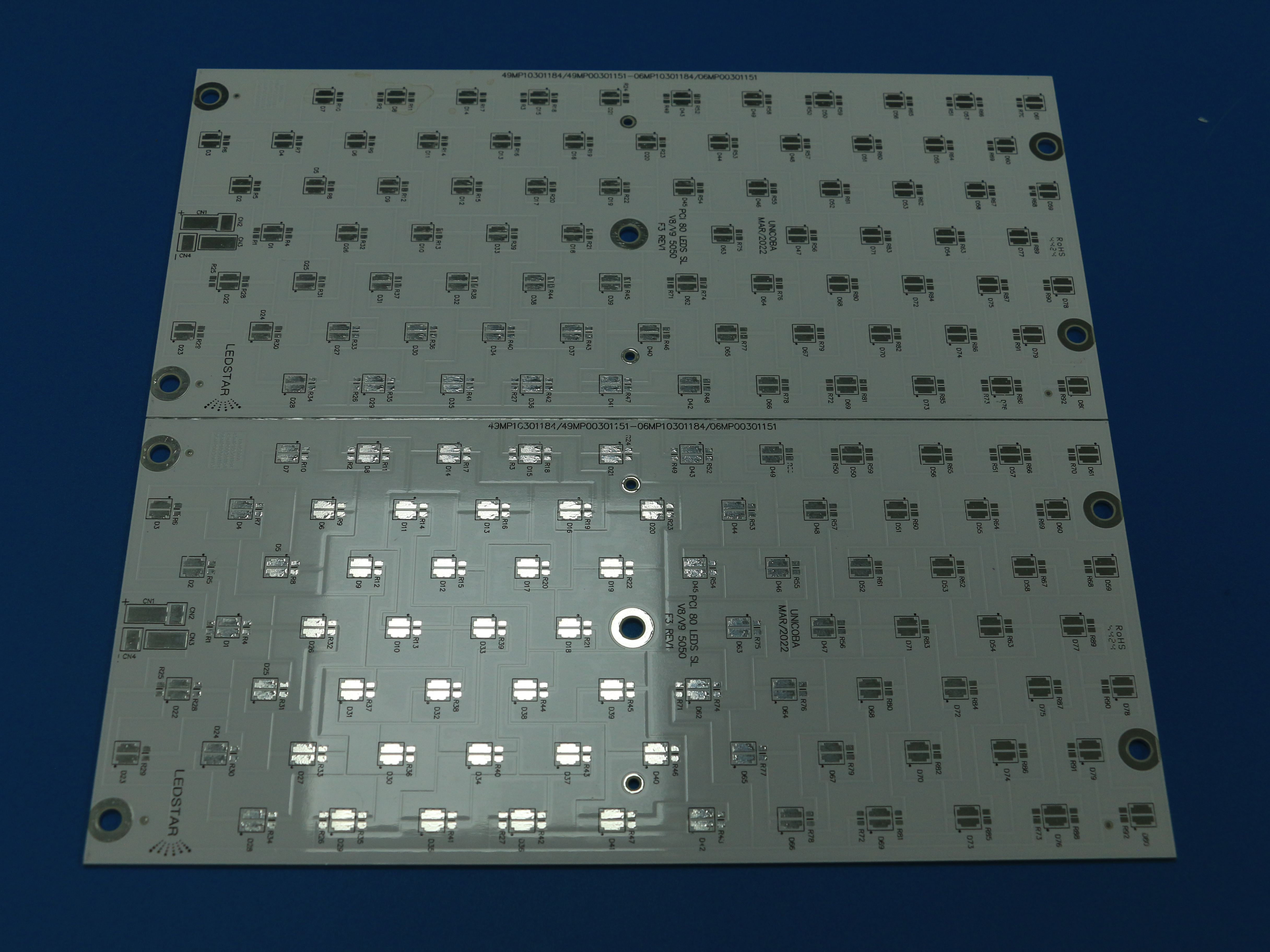
Single-sided aluminium-based MCPCB of the type specified for road lighting modules. Image: WODE Circuit Technology (Zhuhai) Co., Ltd.
Motor lighting: Al5052 with a matt black solder mask
The MCPCB for motor lighting resolves the same four decisions differently. Its base is Al5052, a 5xxx-series aluminium alloy. Alloy choice on a lighting board is normally tied to the mechanical and environmental context of the lamp rather than to the board function alone, and vehicle lighting is a context in which the board becomes part of a moving assembly.
| Product | MCPCB for Motor lighting |
| Base material | Al5052 aluminium |
| Layer count | Single sided |
| Copper foil thickness | 1 oz |
| Overall thickness | 1.6 mm ±10% |
| Panel size | 243.00 mm × 243.00 mm (1-up) |
| Solder mask | Matt black |
| Silkscreen colour | White |
| Surface finish | HASL |
The panel format is the most visible structural difference. Where the road lighting board is delivered as a two-up panel measuring 208.00 mm by 225.00 mm, the motor lighting board is delivered as a single-up panel of 243.00 mm by 243.00 mm. For a buyer, that changes panel handling, fixture design and the arithmetic of how many finished lamp boards come out of one production panel. It does not, on its own, say anything about which board is preferable — the formats serve different assembly layouts.
The mask and legend scheme is inverted relative to the road lighting board: matt black solder mask with white silkscreen. Dark mask colours are commonly specified where the board sits behind or beside an optical element and a low-reflectance surface is wanted inside the lamp housing. The surface finish on this board is HASL rather than HASL-LF, which is a detail a procurement team should record rather than assume, because finish affects the soldering process window and the documentation that accompanies the part.
Shared ground and points of divergence
Placed side by side as specifications rather than as performance claims, the two boards converge on several fields and separate on others.
| Specification field | Road lighting board | Motor lighting board |
|---|---|---|
| Base material | Al1060 | Al5052 |
| Layer count | Single sided | Single sided |
| Copper foil | 1 oz | 1 oz |
| Thickness | 1.6 mm ±10% | 1.6 mm ±10% |
| Panel format | 208.00 × 225.00 mm, 2-up | 243.00 × 243.00 mm, 1-up |
| Solder mask | White | Matt black |
| Surface finish | HASL-LF | HASL |
The pattern is instructive for anyone building a specification. The electrical backbone of the two boards is identical on paper: one copper layer at 1 oz, one aluminium base at 1.6 mm with the same tolerance. What changes is everything the application touches — the alloy, the panel format, the mask colour, the legend colour, the finish. A buyer comparing MCPCB quotations across lighting projects should therefore expect differentiation in exactly those fields, and should treat a supplier who cannot explain why those fields differ as a specification risk rather than a cost advantage.
Reading a lighting MCPCB specification sheet
Because the same category name covers boards built for different fixtures, the specification sheet is the place where a buyer separates a fit from a near miss. Six fields do most of that work.
1. Base alloy. Al1060 and Al5052 are different aluminium families. Recording the alloy is the minimum requirement; leaving it as aluminium means the board cannot be reordered consistently.
2. Layer count. Both lighting boards here are single sided. Where a lighting design needs denser interconnect, the same catalogue moves to other constructions entirely — for example a Double sided MPCB in Al5 material at 70/70 µm copper with 56 units per panel, listed for home applications.
3. Copper foil thickness. Stated in ounces or micrometres depending on the board; the lighting boards in this article are both 1 oz, while the thermoelectric separated copper-based board is listed at 35 µm.
4. Overall thickness and tolerance. A 1.6 mm board quoted at ±10% is a range, not a point value. Mechanical designers should plan clearances against the range.
5. Panel size and upside. Panel dimensions plus the number of units per panel determine production economics and handling. The same supplier catalogue lists 208.00 × 225.00 mm (2-up), 243.00 × 243.00 mm (1-up), and 133.80 × 120.00 mm (4-up) formats on different lighting and lighting-adjacent products.
6. Surface system. Solder mask type, silkscreen colour and surface finish travel together. The catalogue shows the range in use: white solder mask with HASL-LF on the road lighting board, matt black mask with HASL on the motor lighting board, white coverlay with HASL-LF on the Coverlay Aluminium PCB, and OSP on the High Voltage MCPCB and the thermoelectric separated copper-based board.
Operating conditions that shape the requirement
The reason the fields above diverge is that lighting environments diverge. Published operating conditions for the lighting industry give a useful frame of reference for buyers writing a requirement.
Indoor lighting is generally handled within 0°C to +40°C at 30% to 80% humidity. Outdoor lighting faces a wider envelope: –40°C to +50°C, high humidity, salt spray, ultraviolet radiation and wind-driven rain. Automotive and vehicle lighting is harsher again, with engine compartment conditions from –40°C to +125°C alongside vibration, shock, oil contamination and moisture condensation. Typical project types in the same reference set include street and outdoor categories through to headlamps, taillights, daytime running lights, ambient lighting and turn signals.
Those conditions map onto documented requirements rather than preferences. Outdoor lighting is expected to meet IP65 or IP67 protection, with salt spray testing at 1,000 hours or more. Automotive lighting references AEC-Q102 qualification for LED devices, LM-80 lumen maintenance testing and ISO 16750 electrical load standards. Thermal expectations are stated as targets: aluminium substrate thermal conductivity of at least 1.5 W/m·K, rising to 3.0 W/m·K or above for high-power designs, with junction temperature held at 85°C or below and preferably at or under 75°C. Service life is commonly framed as 50,000 hours or more under the L70/B50 convention, with automotive lighting cited at 10,000 hours or more.
What this means for an MCPCB buyer is that the board specification is one input into a system requirement, not the system requirement itself. A board can match its published specification exactly and still sit inside a luminaire that fails an outdoor standard, because the enclosure, the driver, the optical assembly and the thermal interface all contribute. Specification sheets should be read alongside the fixture-level requirement.
Where this design approach has limits
Application-specific MCPCBs solve a real problem, but they carry boundaries that a buyer should recognise before committing to a design.
Single-sided routing is a constraint, not a neutral choice. Both boards discussed here have one copper layer. That is sufficient for many LED lighting circuits, but designs that need denser interconnect or a second routing layer have to move to another construction, such as the double-sided aluminium-based board listed for home applications, or to a different board family altogether.
Copper weight is fixed in the published specification. The 1 oz copper on these two lighting boards is the specified figure. A project that assumes heavier copper for current-carrying reasons cannot treat it as a minor variation; it becomes a different board and should be quoted as one.
Surface finishes differ between products. HASL, HASL-LF, OSP and coverlay all appear in the catalogue on different items. Available finish is therefore a per-product fact, and a request for a lead-free finish on a board listed with standard HASL is a specification change rather than a documentation preference.
A specification is not a test report. Published parameters describe what the board is designed and manufactured to, not how any particular assembly performed in a given fixture. Buyers who need thermal or reliability evidence should require that evidence separately and should not infer it from a data sheet. No performance comparison between the boards described here is made or implied.
Board-level selection cannot compensate for fixture-level design. The MCPCB carries the LED string and provides the metal base. It does not replace the driver electronics, the optical system, the sealing strategy or the thermal interface between the board and the housing.
How WODE approaches application-specific MCPCBs
WODE Circuit Technology (Zhuhai) Co., Ltd. is a PCB and FPC manufacturer established in 2003, based in Zhuhai, China. The company employs approximately 500 staff across a 150,000 m² manufacturing facility, with an annual production capacity of 6,000,000 m². Its product range covers rigid MCPCB, FPCB, infinity length FPCB, FR-4, CEM1 and CEM3 PCBs, copper clad laminate and PCB inks, and its engineering organisation includes a 15-person R&D team working with more than 40 patented technologies.
The company holds ISO9001, ISO14001 and IATF16949 certifications, and states that its products comply with UL, RoHS and REACH standards. Export business accounts for around 50% of sales, with named markets including Brazil, Turkey, India, Vietnam and Russia, and a customer base of more than 1,000 customers across more than 30 countries.
For lighting buyers, the relevant part of that profile is the product structure rather than the scale. The catalogue separates road lighting, motor lighting, high voltage lighting, home application and phototherapy boards into distinct specification entries rather than offering a single generic MCPCB. That structure is what allows a buyer to source road lighting and motor lighting boards from one supplier while keeping the alloy, panel format and surface system recorded as separate line items.
Market context: application-specific boards are replacing generic listings
The shift visible in this catalogue — from a generic MCPCB offer to a set of boards named after the fixture they serve — reflects a broader change in how lighting hardware is specified.
Outdoor and vehicle lighting expectations have become more explicit. Where a road lighting requirement once stopped at board material, it now commonly includes IP65 or IP67 protection, salt spray testing at 1,000 hours or more, junction temperature targets and a service-life figure expressed under L70/B50. Vehicle lighting brings its own reference set: AEC-Q102 for LED devices, LM-80 lumen maintenance and ISO 16750 electrical load standards. Requirements of that kind are difficult to satisfy with an undifferentiated board.
At the same time, lighting designs continue to push optical power into smaller mechanical envelopes, which raises the importance of the board as a thermal element rather than only an electrical one. The practical consequence for procurement is that supplier evaluation increasingly turns on whether a supplier can hold a stated alloy, thickness tolerance, panel format and finish consistently across repeat orders — and can document that it does.
Future outlook
Two directions seem likely to shape lighting MCPCB sourcing over the next few years. The first is further specialisation: more board entries named after the fixture and operating environment, with alloy, panel format and surface system treated as application variables rather than catalogue defaults. The second is tighter documentation. As outdoor and automotive requirements become more standardised, the specification sheet is likely to carry more of the evidence a buyer needs — tolerance statements, finish declarations, compliance references — and less of the informal reassurance that has historically filled that role.
For buyers in the awareness and research stages, the practical takeaway is simple. Treat MCPCB as a starting category and the four specification decisions — alloy, layer count, panel format, surface system — as the actual subject of the enquiry. The boards described here differ in exactly those fields, and those fields are what a quotation should make explicit.
FAQ
What is an MCPCB in a lighting context?
An MCPCB is a printed circuit board built on a metal base rather than an FR-4 laminate. In lighting, the base is typically aluminium, which gives the board a mechanical and thermal function in addition to carrying the LED and driver circuit. WODE Circuit Technology (Zhuhai) Co., Ltd. lists rigid MCPCB among its main product lines, alongside coverlay aluminium boards, double-sided aluminium boards, thermoelectrically separated copper-based boards and ceramic-based boards.
Which aluminium alloys appear on lighting MCPCBs, and why do they differ?
The MCPCB for road lighting is built on Al1060 aluminium, while the MCPCB for motor lighting is built on Al5052 aluminium. The two alloys come from different aluminium families, and the published specifications assign them to different lighting scenarios rather than to a single generic lighting board. Buyers should record the exact alloy on the specification sheet, because it defines what can be reordered consistently.
What panel size and thickness should be expected on a road lighting MCPCB?
The published specification for the MCPCB for road lighting gives a panel size of 208.00 mm by 225.00 mm delivered as a 2-up panel, an overall thickness of 1.6 mm ±10%, copper foil thickness of 1 oz, a white solder mask, black silkscreen and a HASL-LF surface finish. The ±10% figure is a tolerance band, so mechanical clearances should be planned against the range rather than the nominal value.
Why does the motor lighting MCPCB use a matt black solder mask?
The motor lighting board is specified with a matt black solder mask and white silkscreen, on an Al5052 base, in a single-up panel of 243.00 mm by 243.00 mm at 1.6 mm ±10% overall thickness with 1 oz copper and a HASL finish. Dark mask colours are commonly specified where a low-reflectance surface is wanted inside a lamp housing. The mask colour is part of the published specification, so it should be confirmed as a fixed requirement rather than treated as a cosmetic option.
Is a single-sided MCPCB sufficient for a lighting design?
Both the road lighting and motor lighting boards in this article are single sided, which is enough for many LED lighting circuits. Single-sided construction does constrain routing and interconnect density, however, and it is not the only option available. WODE also lists a double-sided aluminium-based board in Al5 material with 70/70 µm copper, 1.6 mm ±0.16 mm overall thickness and 56 units per panel for home applications, plus a thermoelectrically separated copper-based board for lighting. Design requirements, not preference, should decide which construction is appropriate.
What operating conditions and standards should be considered for outdoor and vehicle lighting boards?
Published lighting-industry conditions describe indoor lighting at 0°C to +40°C and 30% to 80% humidity, outdoor lighting at –40°C to +50°C with high humidity, salt spray, ultraviolet radiation and wind-driven rain, and automotive lighting at –40°C to +125°C in the engine compartment with vibration, shock, oil contamination and moisture condensation. Corresponding requirements include IP65 or IP67 protection and salt spray testing of 1,000 hours or more for outdoor lighting, AEC-Q102 qualification for LED devices, LM-80 lumen maintenance and ISO 16750 electrical load standards for automotive lighting, aluminium substrate thermal conductivity of at least 1.5 W/m·K (3.0 W/m·K or above for high power), and junction temperature at or below 85°C.
What should a buyer verify on a specification sheet before requesting samples?
Six fields carry most of the decision weight: base alloy, layer count, copper foil thickness, overall thickness with tolerance, panel size with the number of units per panel, and the surface system of solder mask, silkscreen and finish. On the WODE catalogue these fields vary between products — 1 oz copper on the road and motor lighting boards against 35 µm on the thermoelectrically separated copper-based board, and HASL-LF, HASL, OSP and white coverlay appearing across different items. Finish and mask availability are per-product facts, so an assumed finish should always be confirmed. Compliance documentation, such as ISO9001, ISO14001, IATF16949, UL, RoHS and REACH references, is a separate verification step and should be requested alongside the specification.
A downloadable brochure covering WODE Circuit Technology’s product and manufacturing overview is available here.