
Custom Optical Lens for Automotive Lighting: Spec Guide
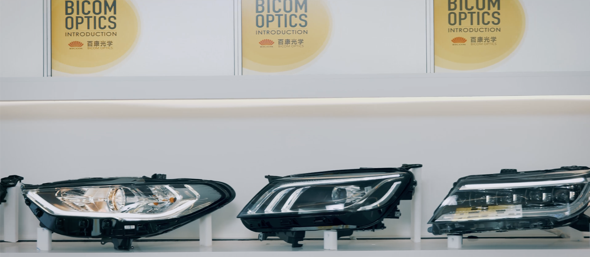
Automotive headlamp and lighting lens assemblies shown as physical samples. Behind every sample sits a constraint set that decides whether the part can be approved and supplied.
An automotive lighting lens is approved as an optical component but purchased as a risk-managed part, and the two views rarely agree. A low-beam inner lens has to land a cutoff line under a specified test condition. A thick-wall turn-signal optic has to hold an integrated appearance against the rear lamp lens while surviving vibration and impact. A light guide may run over a metre through a lamp housing and still deliver uniform output without visible bright spots. Each requirement is testable, and each one tightens the freedom available to the others.
This guide works through that constraint set as it applies to custom optical lens sourcing for automotive lighting. It is written for buyers and design engineers in the research and evaluation stage, where the useful question is not whether a lens can be moulded at all, but which constraints a candidate supplier can actually evidence — with parameters, test data and certificate scope rather than with adjectives.
Why automotive optical parts cannot be specified like general lighting optics
In general illumination, a lens is usually evaluated on its own terms: beam angle, uniformity, transmission, cost. An automotive lighting lens is evaluated inside three nested systems. The first is the vehicle, which imposes a thermal environment and a vibration profile. The second is the lamp assembly, which imposes stack-up tolerances, optical axis alignment and often an aesthetic requirement about how the optic reads behind a clear outer lens. The third is the regulatory approval of the lamp as a device, which the lens must not violate.
The practical consequence is that automotive optical parts are constraint-driven rather than feature-driven. A supplier that can quote an attractive beam angle but cannot demonstrate cutoff stability, thermal headroom or an approval-relevant certificate is answering a question the buyer did not ask. Conversely, a supplier whose parameter envelope is narrower but fully documented is often the lower-risk selection, because the boundaries are known before tooling is cut.
The five constraint layers buyers actually manage
- Photometric: beam angle and distribution, cutoff sharpness, stray light, uniformity along an elongated zone.
- Thermal: operating temperature at the lens body, LED power class, long-hour stability, UV exposure.
- Mechanical and assembly: wall thickness, curvature fit, assembly clearance, resistance to vibration and impact.
- Regulatory: the approval path of the lamp device and the manufacturing-system certificates behind it.
- Manufacturability and traceability: mould feasibility, cavity count, shrinkage and warpage control, batch records.
Most failed sourcing projects fail at the boundary between two layers rather than inside one. A design that is photometrically sound but sits at the top of its material's thermal range, or a thick-wall part that meets its drawing but warps in the fourth cavity, is a boundary failure. That is why the evaluation sequence below follows layers rather than product names.
Layer one: material and thermal envelope
Custom optical lenses for lighting are normally produced in optical-grade polycarbonate (PC) or polymethyl methacrylate (PMMA). The two materials trade optical performance against thermal headroom, and the trade is quantified rather than approximate.
- Light transmission: greater than 90% for PMMA; greater than 88% for PC.
- Operating temperature: −40 °C to +120 °C for PC; −40 °C to +90 °C for PMMA.
- Lens size range: 5 mm to 1500 mm, customizable.
- Beam angle range: 2° to 120°, covering spot to flood distributions, customizable.
The decision rule that follows is straightforward. Where the optic sits close to a high-power LED and local temperature can approach the upper part of the range, PC is the defensible choice even at a small transmission penalty. Where the application is transmission-critical and thermally moderate — a signal optic, an ambient light guide, an interior or rear lamp element — PMMA's higher transmission is available without thermal risk.
The boundary deserves stating plainly: PMMA's +90 °C ceiling is a real limit, not a conservative footnote. A design that assumes PMMA in a position where the lens body will exceed that ceiling is a design that will age badly, and no amount of downstream testing repairs the material choice.
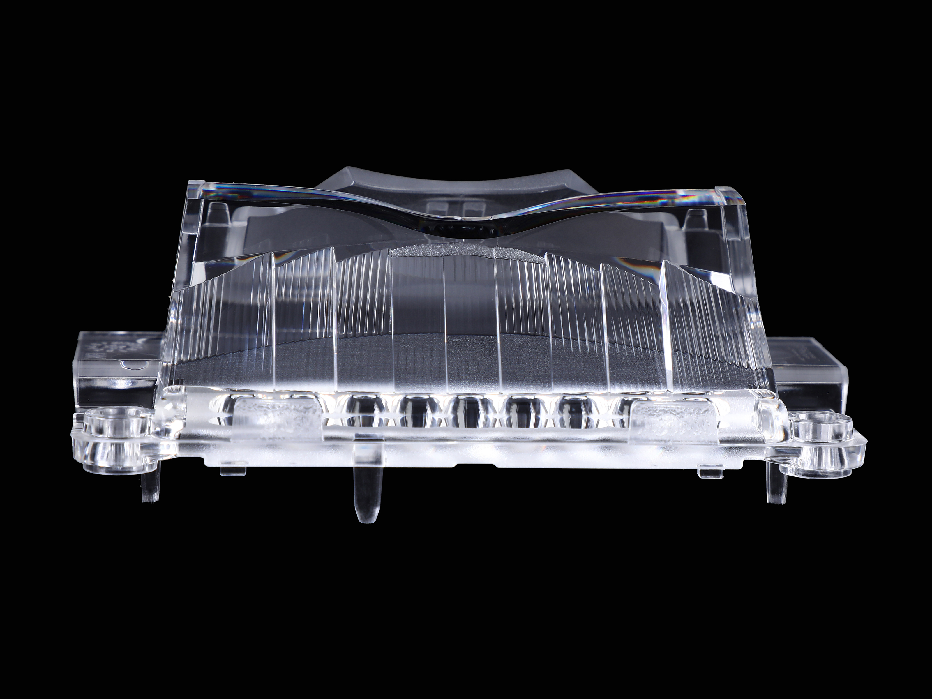
A low-beam inner lens: tapered optical cavities arranged horizontally, each distributing light from an individual LED.
Layer two: photometric constraints
Automotive photometry is where the constraint language becomes concrete, because the outputs are measurable files rather than descriptions.
Low beam: cutoff and stray light
A low-beam inner lens is typically built as a multi-cavity optical array: multiple tapered or cup-shaped optical cavities arranged horizontally, with each cavity supporting independent light distribution for an individual LED. The inner surface is a free-form curved surface designed to capture and collimate light, which reduces optical loss and improves luminous efficacy. The point of the array is not brightness in aggregate but control. The cutoff line is produced by the combined behaviour of the cavities, so a single weak cavity shows up as a defect in the beam pattern rather than as a small efficiency loss.
Combined high and low beam
A combined headlamp lens integrates the optical surfaces for both functions in one part. Complex asymmetric free-form surfaces are arranged so that the low-beam cutoff line and the high-beam long-range performance are optimised separately, while stepped and precision-curved internal structures limit stray light during switching. The engineering value is part-count reduction and a smaller module; the procurement value is one approved optical interface instead of two.
Uniformity along a line or a guide
Light guides and linear lenses are judged on evenness. A light guide uses a precision light-guiding structure to distribute light evenly through the component, with the design intent of reducing obvious bright spots and dark areas, and it is designed to work with low-power LEDs at low energy loss. A linear lens applies the same logic to an elongated lighting zone, delivering even illumination and uniform strip lighting rather than a row of hot spots.
For evaluation purposes, the evidence to request is specific: an IES photometric file, ray-trace data, and a beam-angle and light-distribution test result tied to the actual cavity count of the production mould.
Layer three: dimensional and assembly constraints
An automotive lens is rarely a free-standing part. Thick-wall optics for rear signal lamps illustrate the pattern. A thick-wall transparent body provides structural strength and resistance to vibration and impact; a large-curvature free-form profile is shaped to closely fit the rear lamp lens with minimal assembly clearance; and a dense micro-prism structure on one edge refracts and distributes light evenly. The appearance requirement and the mechanical requirement are satisfied by the same moulded geometry, which is why such a part cannot be re-specified as a thin lens plus a separate carrier without changing the lamp's design.
Monolithic moulding reduces part count but moves difficulty upstream into tooling and process. Design-for-manufacture review for these parts has to cover optical surfaces, wall thickness, gate location, ejector pins, parting lines, cavity quantity, shrinkage and deformation. Each item can silently convert a photometrically correct design into a part that fails dimensional inspection at the fourth cavity.
Layer four: the certification stack, read correctly
Certificates are frequently listed as a block and evaluated as a block. They answer different questions, and in an automotive programme the differences matter.
- IATF 16949:2016 — certificate IATF 0549923, issued by SGS, valid 2024-10-15 to 2027-10-14. Scope: manufacture of LED light lenses; design and manufacture of LED light modules. This is the automotive quality management system certificate, and it is normally the first document a tier-1 buyer screens.
- ECE Conformity of Production — certificate C1 51262503, issued by UCA (Unidad de Certificación del Automóvil) under E/ECE/TRANS/505/Rev.3, issued 2020-03-10, valid to 2028-03-10. Scope: retro-reflecting devices, lamps and light signalling devices for power-driven vehicles and their trailers, applicable to automotive lighting lenses in the EU and global markets. This is the approval-relevant document for the lamp device class.
- ISO/IEC 17025:2017 laboratory accreditation — CNAS L22447, issued by the China National Accreditation Service for Conformity Assessment, valid 2025-02-06 to 2031-02-05. Scope includes testing and calibration laboratory activities for custom optical lens measurement reports, batch traceability documentation and automotive lighting lens applications. This one determines whether the supplier's own measurement reports carry accreditation weight.
- ISO 9001:2015 — certificate 0282Q11279R1M, issued by Zhong An Certification, valid 2025-07-11 to 2028-07-20; scope covers design and production of lenses including LED lenses, lamp moulds and sensor products.
- ISO 14001:2015 — certificate 02819E10401R2M, valid 2025-07-11 to 2028-07-23, covering environmental management activities in the design and production of lenses, lamp moulds and sensor products.
- ISO 45001:2018 — certificate 02819S10369R2M, valid 2025-07-11 to 2028-07-23.
- ISO 50001:2018 — certificate 04426En00060R001, issued by Beijing Zhongjing Quality Certification Co., Ltd., valid 2026-05-29 to 2029-05-28.
- ESG audit completion — issued by MARELLI for the Zhejiang Bicom Optics Co., Ltd Jiaxing Plant, valid 2026-05-12 to 2029-05-11; certificate number field listed as not applicable, with no standard code listed.
Two practical rules follow. First, every certificate carries a validity window, and the windows differ: at the time of writing the IATF certificate runs to October 2027 while the ECE CoP certificate runs to March 2028. A supplier pack assembled two years earlier may already be out of date. Second, scope wording is the part that decides relevance. A quality certificate for lens manufacturing does not automatically cover module design, and a Conformity of Production for signalling devices does not automatically extend to a different lamp category.
Where Zhejiang Bicom Optics sits in this constraint map
Zhejiang Bicom Optics Co., Ltd is an optical lens and precision injection mould manufacturer based in Jiashan County, Jiaxing City, Zhejiang Province, China, founded in 2005. The company operates a 90,000 m² facility with approximately 700 employees and an annual output of 90,000,000 pieces, holds 167 patents (17 invention patents and 150 utility model patents), and exports about 30% of production to markets including the EU, USA, the Middle East, Japan and Korea.
Its stated process envelope is what makes the automotive constraint set addressable in-house. Toolroom capability is described as nanoscale CNC machining with positioning accuracy up to 10 nanometres and mould cavity precision adjustable to within 5 microns. Part capability includes high-precision thick-wall lenses up to 50 mm thick and automotive light guides up to 1,300 mm in length, and the company states it can mould two-colour and three-colour products in a single production run. Optical design, precision mould design and manufacturing are positioned as core competencies, with a customization model applied per product rather than per catalogue.
For a buyer, the relevant reading is not the size of the facility. It is that the three capabilities which most often block automotive lens projects — thick-wall moulding, long light-guide uniformity and multi-shot construction — are each stated with a numeric boundary that can be tested against a drawing.
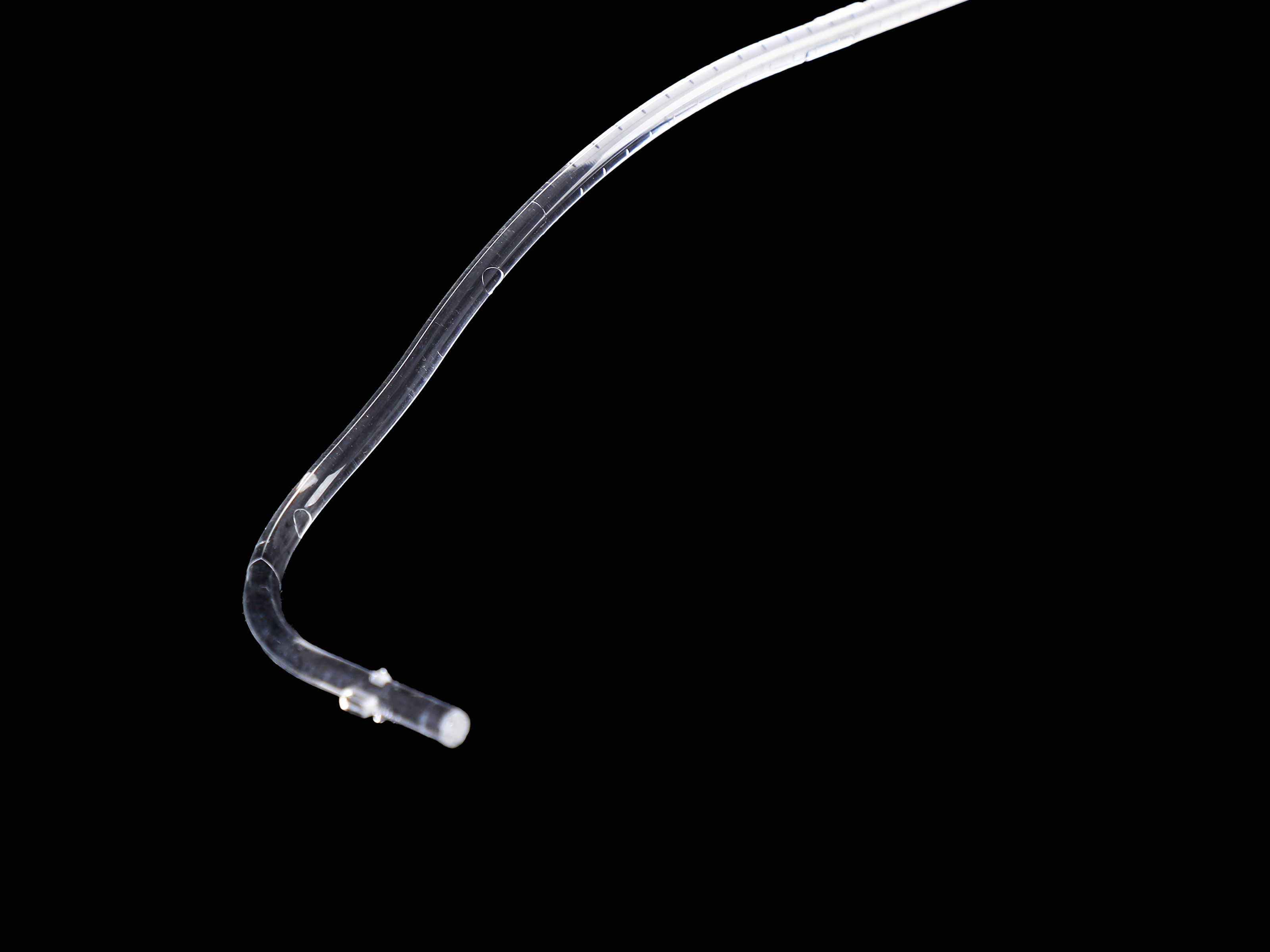
An automotive ambient lighting light guide. Uniformity along the length and resistance to yellowing over service life are the two properties that decide field performance.
Technical explanation: the three process constraints that decide feasibility
Thick-wall moulding
Wall thickness above roughly ten millimetres changes the moulding problem. Cooling is no longer uniform through the section, volumetric shrinkage becomes significant, and the risk of sink marks and warpage rises together with the optical surface requirement. The automotive answer is often a thick-wall transparent body that doubles as a structural element, which is precisely why the wall cannot simply be thinned. Holding optical surface fidelity at 50 mm thickness is a tooling and process-parameter problem, not a design preference.
Long light guides
A light guide approaching 1,300 mm introduces two failure modes that short guides do not have. The first is uniformity drift along the length, where extraction features that work at 300 mm produce visible banding at 1,200 mm. The second is end-of-life optical decay: the material must resist yellowing, embrittlement and light decay during long-term operation, as well as heat, UV ageing and vibration. Optical-grade material selection and precision light-guiding structure design address the first; material grade addresses the second.
Multi-cavity arrays
A multi-cavity array concentrates risk. Every cavity must produce the same optical result, so cavity-to-cavity variation becomes a beam-pattern issue rather than a cosmetic one. Multi-cavity mould management, standardised injection parameters and inspection of critical dimensions across cavities are the controls that keep the array inside specification.
Application fit: where the constraint set applies
The lens types described here map to defined automotive functions: headlamp low beam and high beam, combined low and high beam modules, fog lamps, daytime running lights, rear turn signal and signalling optics, and ambient lighting. The stated working environment for these parts is indoor and outdoor operation across −40 °C to +105/120 °C, with high humidity, UV exposure, vibration and continuous operation. Matched hardware typically includes high-power or COB LEDs, LED modules, heat sinks, drivers, reflectors and housings.
The fit test for a buyer is whether a candidate lens family covers the functions in the programme without leaving the material envelope. A programme that spans a high-power headlamp and a low-power ambient light will usually end up specifying PC in one position and PMMA in the other, and the supplier needs to be competent in both rather than optimised for one.
Market trend analysis: what is driving specification tightness
Two published data points frame the direction of travel, and both should be read with their definitions attached.
Fortune Business Insights places the global optical lens market at USD 21.08 billion in 2025. That figure covers optical lenses as a category, including ophthalmic alongside industrial and lighting optics. It is a scale indicator for the supply base rather than a lighting-optics market size, and it should not be used to size the automotive lens segment.
TrendForce / LEDinside projects that vehicles equipped with adaptive driving beam (ADB) headlights will reach a penetration rate of 23.8% by 2030. This is the more directly relevant signal. ADB depends on selectively controllable light distribution, which raises the requirement on the optic: finer segmentation, tighter cutoff control and lower stray light than a fixed beam pattern demands. Those requirements are met through multi-cavity arrays, free-form surfaces and multi-zone designs — the same part families discussed above.
The reasonable inference is directional rather than quantitative. As beam control becomes a differentiating function, the optical part absorbs a larger share of the lamp's engineering effort, and suppliers who can evidence beam-level control move up the evaluation list.
Comparison with conventional approaches
Fresnel versus conventional thick lens. A Fresnel design uses annular prismatic facets or microstructures to converge, collimate or redistribute light, and its structure provides a thinner profile than a conventional thick lens of similar focal length while delivering equivalent light control. Where size and weight are constrained, that is decisive. Where structural strength and an integrated thick-wall appearance are required — the rear signal lamp case — the Fresnel route does not substitute, because the thick body is doing mechanical work as well as optical work.
Multi-cavity array versus single large optic. An array gives per-LED control and a compact, lightweight module, at the cost of cavity-to-cavity consistency management. A single large optic simplifies consistency but gives up the ability to shape individual LED contributions, which matters under ADB-type requirements.
Custom tooling versus off-the-shelf optics. Custom tooling delivers the beam pattern, fit and appearance the lamp was designed around, but it requires a complete requirement package and a development cycle. Off-the-shelf lenses avoid tooling cost and lead time but constrain the lamp design to whatever distributions already exist.
The honest boundary is this: custom automotive optical tooling is a poor fit for very small volumes, for replacement parts without drawings, and for programmes that cannot supply optical data. Quoted minimum order quantities for custom optical lenses sit in the 1,000 to 5,000 piece range depending on project, prototypes and samples typically run 7–12 days, and mass production delivery typically runs 7–20 days depending on quantity and complexity. Those numbers are workable for a production lamp programme and uneconomic for a one-off.
Procurement checklist for the evaluation stage
| Constraint layer | What to specify | Evidence to request |
|---|---|---|
| Photometric | Beam angle and distribution, cutoff, stray-light target, uniformity | IES file, ray-trace data, beam angle and light distribution test report |
| Material and thermal | PC or PMMA, transmission target, operating temperature at the lens body | Material grade statement, transmission test result, thermal data |
| Dimensional | Tolerances, assembly clearance, curvature fit, wall thickness | CMM dimensional report, 3D scan data |
| Regulatory | Target market, lamp category, device approval route | IATF 16949 certificate, ECE CoP certificate with scope wording |
| Traceability | Batch and cavity identification, inspection records | Lot traceability documentation, accredited measurement reports |
| Supply | Volume, ramp profile, delivery window | Stated capacity, lead time, multi-cavity mould capability |
Limitations worth stating before tooling
- PMMA carries a +90 °C operating ceiling; positions near high-power LEDs should be specified in PC.
- Thick-wall parts carry longer cycle times and higher warpage risk than thin lenses, and mould cost reflects that.
- Custom development requires 2D drawings, 3D data, optical data, material requirements, application and operating environment before manufacturability, cost and lead time can be assessed.
- Minimum order quantities of 1,000 to 5,000 pieces make the custom route unsuitable for very small or one-off volumes.
- A certificate's scope wording, not its existence, determines whether it applies to a specific lamp category or market.
Future outlook
Three developments are likely to tighten the constraint set further. Adaptive and segmented beam functions raise the number of optical channels per lamp, pushing demand toward multi-cavity arrays and free-form surfaces rather than simpler rotationally symmetric optics. Ambient and signalling lighting continues to move toward long light guides, where uniformity and UV stability over service life are the deciding properties. And traceability expectations are rising in parallel with the certificate stack: accredited measurement reports and lot-level records are becoming part of the routine supplier pack rather than a special request.
None of these changes alter the underlying evaluation logic. They increase the weight carried by the evidence a supplier can produce — parameters, test data, certificate scope and traceability — relative to the weight carried by the parts catalogue.
FAQ
What documents are typically required before a custom automotive lighting lens project can be quoted?
Customers generally need to provide 2D drawings, 3D data, optical data, material requirements, product application and operating environment. The detail covers product dimensions, tolerances, optical surfaces, assembly requirements, surface roughness, light-source information, material grade, working temperature and relevant performance requirements. This package allows a supplier to evaluate manufacturability, cost and development lead time accurately. Where the package is incomplete, design-for-manufacture review is usually delayed rather than skipped.
How can a buyer verify genuine custom development capability rather than drawing-based production?
The check is full-cycle rather than drawing-based. A capable supplier covers optical design, structural evaluation, DFM, mould-flow analysis, mould design and fabrication, precision injection moulding, optical testing and mass-production support. Verification typically combines past custom project references, similar-product experience, the engineering team and the production equipment list. The distinguishing question is whether the supplier can co-develop the part, or only manufacture strictly to customer drawings.
What does the sampling and approval path look like from requirement confirmation to mass production?
Custom optical components normally follow the sequence: requirement confirmation, engineering assessment, DFM, quotation, mould development, T0 sampling, test and validation, optimisation, customer approval, then mass production. Either a prototype mould or a production mould can be used depending on project phase. Completed samples are validated for dimensions, optical performance, appearance and assembly against the product specification, and mould or process adjustments follow from those results. Mass production begins after customer confirmation.
How is batch-to-batch consistency controlled on a multi-cavity automotive lens?
Consistency is controlled across several links rather than at final inspection only: raw material supply, moulds, injection-moulding process parameters, dimensional inspection, optical performance and appearance. Multi-cavity mould management, standardised injection parameters, inspection of critical dimensions and optical performance, and defined inspection standards with in-process control keep output stable across batches and cavities. Production traceability and continuous process monitoring are used to identify and mitigate quality risks early.
What supply-side capabilities should be checked for high-volume automotive lens procurement?
Beyond development competence, the evaluation should cover injection-moulding equipment and actual production capacity, multi-cavity mould capability, mould service life, raw-material supply, quality management system, testing capacity, production and engineering team depth, delivery lead time and abnormality response. It is also worth confirming whether the supplier can expand capacity against order growth and urgent demand, since capacity and delivery risk usually surface during ramp-up rather than during sampling.
The constraint set around automotive lighting lenses will not shrink. What changes is how much of it a supplier can document before tooling begins — and that documentation, rather than the shape of the catalogue, is what shortens the distance between an approved design and a stable production part.
Have Questions or Need More Details?
Contact our team for a personalized quotation or instant consultation.
Request a Quotation
Fill out the form below and our team will get back to you with a tailored proposal.
WhatsApp Direct Chat
Prefer to chat in real-time? Message us on WhatsApp for instant assistance & quick answers.
- Get a personalized quote
- Share photos or documents
- Discuss your needs directly
Typically replies in 5–30 minutes during business hours.