
DC Brushless Motor Basics: What Buyers Should Check First
DC Brushless Motor Basics: What Buyers Should Check First
A DC brushless motor, also written as brushless DC motor or BLDC motor, is a direct-current motor whose commutation is performed electronically instead of by carbon brushes and a mechanical commutator. For an equipment team in the awareness and research stage, that single structural difference determines maintenance intervals, acoustic behavior, electromagnetic interference, and often the driver electronics that must be added to the bill of materials. The sections below explain what the brushless category actually contains, how the numbers on a miniature brushless gear motor datasheet should be read, and which points are worth verifying before a design is frozen.
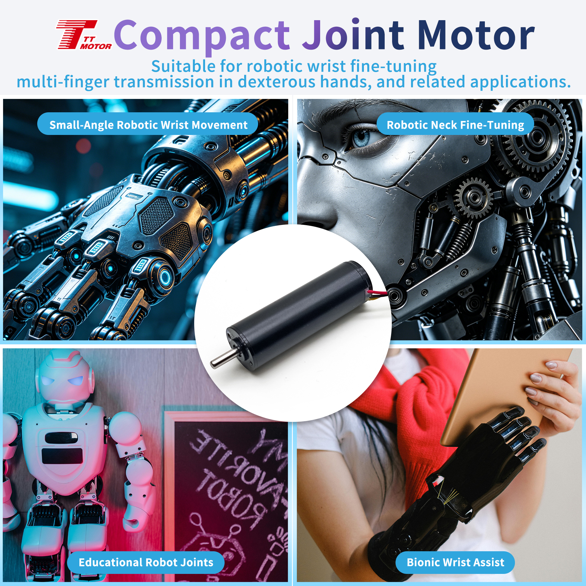
Why Brushless Drives Reached Mainstream Procurement
Brushless drives are no longer a specialist niche, and two independent data points make that clear. The global brushless DC motor market was valued at USD 22.2 billion to USD 22.33 billion for 2025 by Grand View Research and Precedence Research respectively, and both publishers cover a forecast window extending to 2033. At a broader level, world trade in electric motors with an output not exceeding 37.5 W, the customs heading HS 850110 under which most miniature DC motors are classified, was valued at USD 16.3 billion in 2024 according to trade data published by OEC.
Read together, these figures describe a mature supply base rather than an emerging one. The practical consequence for buyers is that brushless construction is now offered in the same miniature envelope sizes that brushed motors have occupied for years. That shifts the procurement question from whether brushless is available at a given size to whether a specific application justifies brushless construction, its control electronics, and its unit cost.
The Problem: Motor Selection Usually Happens Too Late
In many equipment programs the drive is treated as a late-stage component, selected after the enclosure, the user interface, and the power architecture are already fixed. For a brushless motor this sequencing is risky, because three separate decisions arrive at once. First, electronic commutation requires a driver stage, which means control electronics, wiring, and often firmware tuning must be planned alongside the mechanics. Second, the mechanical interface of the gearbox, including shaft diameter, flange pattern, and overall length, constrains the surrounding assembly. Third, acoustic and electromagnetic behavior usually cascade into system-level grounding and shielding choices.
A second, quieter risk sits on the supply side. A motor that performs to specification as a sample can still vary in volume production if raw materials or components are substituted, if the sample process is not locked in, if production equipment or mold condition changes, or if parameter control between batches is inadequate. The industry-standard mitigation is procedural rather than technical: define motor parameters and acceptance standards before mass production, run a small-batch trial production first, establish a shipment inspection mechanism, define sampling or full-inspection rules for key parameters, and require advance notification and re-verification whenever a supplier changes raw materials, components, or production processes.
Both problems share a root cause. Brushless motor selection is usually decided on a single headline number, such as torque or price, when the specification that actually governs field performance is a combination of duty cycle, thermal behavior, gearbox architecture, and control interface. Addressing that combination during the research stage is cheaper than addressing it after tooling.
What Is Inside a Miniature Brushless Gear Motor
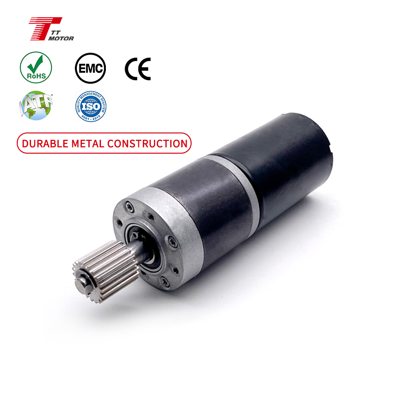
Structurally, a DC brushless gear motor is a brushless motor integrated with a gearbox, and the integration ratio is what separates a well-matched unit from an assembly of parts. In the GMP36-TEC3650, a brushless planetary gear motor in the DC brushless gear motor category, the motor and the planetary gearbox share a 36 mm outer diameter, so the assembly remains a single-diameter cylinder rather than a stepped package. The planetary gears are precision-machined, which results in minimal transmission backlash, and the brushless construction eliminates brush wear so that regular brush replacement is not required. The manufacturer states that the service life of the brushless motor is typically tens of thousands of hours.
Brushless planetary gear motors
Planetary architecture is used where the drive must fit a compact volume while still delivering usable torque at controlled speed. The GMP36-TEC3650 is specified for robotics, medical device, industrial automation equipment, and intelligent logistics equipment, and is designed for compact robotic and automation equipment scenarios. Its operating window is DC 12 V to 24 V, with output speed from 4 rpm to 1600 rpm and a maximum rated torque of 30.0 kg.cm. Ten reduction ratios from 1/4 to 1/720 are available across gearbox configurations of one, two, three, or four stages.
DC brushless worm gear motors
Where right-angle output or position holding is required, a DC brushless worm gear motor becomes the relevant architecture. The TWG3246-TEC2430 uses a right-angle output worm gearbox with brushless construction and electronic commutation. Its self-locking behavior typically means that no additional braking device is required to hold position, and the worm stage achieves a high reduction ratio in a compact body, which suits very slow and smooth fine adjustment. The unit is specified from 3 rpm to 35 rpm at DC 12 V to 24 V with a maximum rated torque of 8.0 kg.cm and a 46 mm gearbox, and is made of stainless steel, iron, and copper.
| Parameter | GMP36-TEC3650 brushless planetary gear motor | TWG3246-TEC2430 DC brushless worm gear motor |
|---|---|---|
| Architecture | Brushless motor with same-diameter planetary gearbox | Brushless motor with right-angle worm gearbox |
| Rated voltage | DC 12 V to 24 V, customizable within range | DC 12 V to 24 V |
| Output speed | 4 to 1600 rpm | 3 to 35 rpm |
| Maximum rated torque | 30.0 kg.cm | 8.0 kg.cm |
| Gear stages | 1, 2, 3, or 4 | 3, 4, or 5 |
| Gearbox length | 26 / 33.5 / 40.5 / 47.5 mm | 46 mm |
| Output interface | 8 mm solid shaft, 4 x M3 mounting flange | Right-angle output, self-locking |
| Net weight | 420 g | Not stated in specification record |
| Materials | Stainless steel, copper, iron | Stainless steel, iron, copper |
How to Read the Numbers on a Brushless Gear Motor Datasheet
Rated torque is defined as the torque that can be continuously output under specified operating conditions. It is a continuous figure, not a peak figure, which means a buyer comparing a 30.0 kg.cm specification against a load requirement should confirm the duty cycle and the ambient conditions under which that value was established. A drive that is asked to hold a load intermittently may tolerate a higher transient load, while a drive asked to run continuously is limited by thermal capacity, bearings, and gear tooth stress rather than by the number on the first line of the datasheet.
Gear stages and reduction ratios form the second reading layer. Long output windows and stronger torque at low speed come from adding stages, and adding stages also lengthens the gearbox. In the GMP36-TEC3650, the gearbox length options are 26 mm, 33.5 mm, 40.5 mm, and 47.5 mm for one, two, three, and four stages, so the overall length ranges from 26 mm to 47.5 mm at an unchanged 36 mm diameter. That trade is usually more acceptable to a machine designer than an increase in diameter, which is why same-diameter architecture is common in compact robotics and medical equipment.
The third layer is the mechanical interface, which is frequently the constraint that kills a project late. An 8 mm diameter solid output shaft and a mounting flange with four M3 holes must match the coupling, pulley, or bracket that already exists. Net weight of 420 g is a further input for handheld or portable devices. Finally, the electrical window matters for more than the motor: a rated voltage range of DC 12 V to 24 V with customization available within that range has to be compatible with the driver stage, and control complexity differs considerably between brushed and brushless designs.
Application Fit: Where Miniature Brushless Drives Are Specified
The applications that pull brushless miniature drives into a design share three characteristics: continuous or high-frequency operation, a low tolerance for maintenance, and either a noise ceiling or an electrical noise ceiling. Robotics is the clearest case. Robot joints operate with high-frequency dynamic motion and rapid start and stop, often with forward and reverse operation and speed change, and are matched with encoders and actuators that demand high power density, fast response, and low inertia. A brushless planetary gear motor designed for compact robotic and automation equipment aligns with those requirements better than a brushed equivalent, because the wear mechanism itself has been removed.
Medical equipment represents the second cluster, and its requirement profile is different. Devices such as urine analyzers, body fluid analyzers, pipetting equipment, infusion syringe pumps, microfluidic dispensers, surgical staplers, and rehabilitation robots operate with low-speed precision motion over long-term operation, and specify low noise, low vibration, and stable operation. The worm gear variant addresses a subset of this space, including miniature medical devices, precision automated instruments, and electrically adjustable supports, where a slow, smooth, self-holding output is more valuable than high speed.
Industrial automation and intelligent logistics equipment form the third cluster, where compact drives are embedded in handling and positioning mechanisms. Smart home and electrically adjustable support products, including height-adjustable desks and similar mechanisms, use the same low-speed positioning logic, and the special requirements stated for that segment are miniaturization, low noise, and low power consumption.
| Application area | Working condition | What to verify first | Typical architecture in the reference portfolio |
|---|---|---|---|
| Robot joints | High-frequency dynamic motion, rapid start and stop | Power density, response, inertia, backlash | Brushless planetary gear motor, GMP36-TEC3650 |
| Medical and laboratory devices | Low-speed precision motion, long-term operation | Noise, vibration, positioning stability | Brushless planetary and DC brushless worm gear motors |
| Industrial automation and logistics | Compact installation, repeatable positioning | Gearbox length, flange and shaft fit | Brushless planetary gear motor |
| Electrically adjustable supports | Slow, smooth fine adjustment with holding | Self-locking, low speed, power consumption | DC brushless worm gear motor, TWG3246-TEC2430 |
| Cost-sensitive compact electronics | Intermittent, simple logic | Unit cost, control simplicity | Brushed spur gear motor, for example GM12-N20VA in the N20 series |
The last row is deliberately included, because the reference portfolio carries both categories. The GM12-N20VA is a DC spur gear motor referenced to the widely used N20 gear motor series, rated at 2.4 V or 5 V with gearbox length of 9 mm or 12 mm and output speed from 12 to 1450 rpm, and is intended for smart door lock scenarios. Published N20 datasheet literature typically describes an envelope on the order of 10 mm by 12 mm by 25 mm with operating voltages spanning 3 V to 12 V, which illustrates that voltage ratings vary by variant and must be confirmed per model rather than assumed from the form factor.
Market Trend Analysis: Efficiency Rules and the Miniature Gap
Regulatory attention on motor efficiency continues to expand. The IEC 60034-30-1:2025 standard introduced an IE5 ultra-premium efficiency class with an effective date of 1 January 2025, and the EU Ecodesign Regulation (EU) 2019/1781 has required IE3 as the minimum efficiency level for motors from 0.75 kW to 1000 kW since 1 July 2021, with IE2 applying to the 0.12 kW to 0.75 kW band. These rules matter to machine builders, but their scope is larger industrial machines. A 12 mm to 42 mm miniature gear motor is normally outside that scope and is instead selected on duty cycle, noise, positioning accuracy, weight, and voltage compatibility.
The practical trend in miniature procurement is therefore not a compliance deadline but a substitution logic. Brushless construction removes the brush and commutator wear mechanism, generates less heat, produces no commutation sparks, and therefore exhibits lower electromagnetic interference than a brushed design of comparable size. Where a mechanism runs continuously, is battery powered, sits close to sensitive electronics, or is expensive to service, that logic increasingly favors brushless. Where operation is intermittent, the logic is simpler and cost dominates.
One data gap is worth stating plainly, because it affects how category-level claims should be treated. There is no reliable public figure for the rate at which brushless gear motors are replacing brushed versions in medical and robotics applications. Buyers should therefore size and select against their own duty-cycle data rather than against a market-wide substitution rate.
Brushless vs Brushed: Comparison and Where Brushless Is Not the Answer
The choice between brushless and brushed construction is usually presented as a straight upgrade path. It is more accurate to describe it as a trade between maintenance economics and control cost.
| Criterion | Brushless motor (electronic commutation) | Brushed motor (mechanical commutation) |
|---|---|---|
| Commutation method | Electronic, no physical contact | Carbon brushes and commutator |
| Wear mechanism | No brush wear, no regular brush replacement | Frictional losses at brushes and commutator |
| Service life as commonly stated | Manufacturer statement of typically tens of thousands of hours | Approximately several hundred to several thousand hours |
| Heat and efficiency | Less heat generation, higher power density | Higher losses for the same envelope |
| Electrical noise | No sparks, low electromagnetic interference | Sparks and carbon dust, strong electromagnetic interference |
| Cost profile | Higher initial cost, virtually no maintenance | Lower initial cost, higher maintenance cost over time |
| Control complexity | More complex control, suited to precise high-performance applications | Simple to control, suited to cost-sensitive, low-lifespan, simple-logic applications |
The limitation is real and it should be stated before a specification is written. Brushless motors are described by suppliers as more complex to control than brushed equivalents, because commutation is handled by electronics that must be specified, wired, and validated. For equipment with intermittent duty, a short expected service life, a cost ceiling, or simple logic, a brushed motor remains the rational choice, and it is why brushed variants such as the GM37-555PM, rated DC 12 V to 24 V with 5 to 800 rpm and a maximum rated torque of 8.0 kg.cm, continue to be specified for automated equipment and automated production lines.
Physical boundaries matter as much as electrical ones. A 36 mm frame diameter, a 420 g mass, an 8 mm shaft, and a four-hole M3 flange have to fit the assembly that already exists. Where available space, overall length, or unit cost is the binding constraint, a smaller brushed spur gear motor may be the more practical starting point even if its maintenance profile is worse. Brushless is a better answer to a maintenance and reliability problem, not a universal answer to every drive problem.
Verification Checklist Before the Design Is Frozen
The following points are the ones that most often surface late in a miniature drive project. Each can be resolved with the supplier during the research stage.
- Confirm the load at the operating point, not the maximum rated torque, and state whether the duty is continuous, intermittent, or positioning-only.
- Confirm the voltage window and whether the required value falls inside the customizable range, then verify driver compatibility with the commutation electronics.
- Confirm gear stage count, reduction ratio, gearbox length, and overall length against the available envelope, since these move together.
- Confirm shaft diameter, flange pattern, and mounting orientation, including whether a right-angle output is required and whether self-locking holding is needed.
- Confirm acoustic and electromagnetic limits, especially for medical, laboratory, and battery-powered devices.
- Confirm the sample-to-batch control plan: locked parameters, defined acceptance standards, small-batch trial production, and a shipment inspection mechanism.
- Confirm that any change to raw materials, components, or production processes triggers advance notification and re-verification.
- Confirm compliance documentation for the exact model and material set, since declarations are made at model level rather than at category level. Most miniature motors in the reference portfolio have passed RoHS testing, with reference to RoHS Directive (EU) 2015/863 amending 2011/65/EU.
Future Outlook
The direction of miniature drive development is toward tighter integration rather than toward higher headline speeds. Same-diameter motor and gearbox architectures reduce the internal volume a designer must reserve, and voltage customization inside an existing range allows one mechanical platform to serve several power architectures. Both trends reduce the number of design iterations a buyer has to absorb when a product line is refreshed.
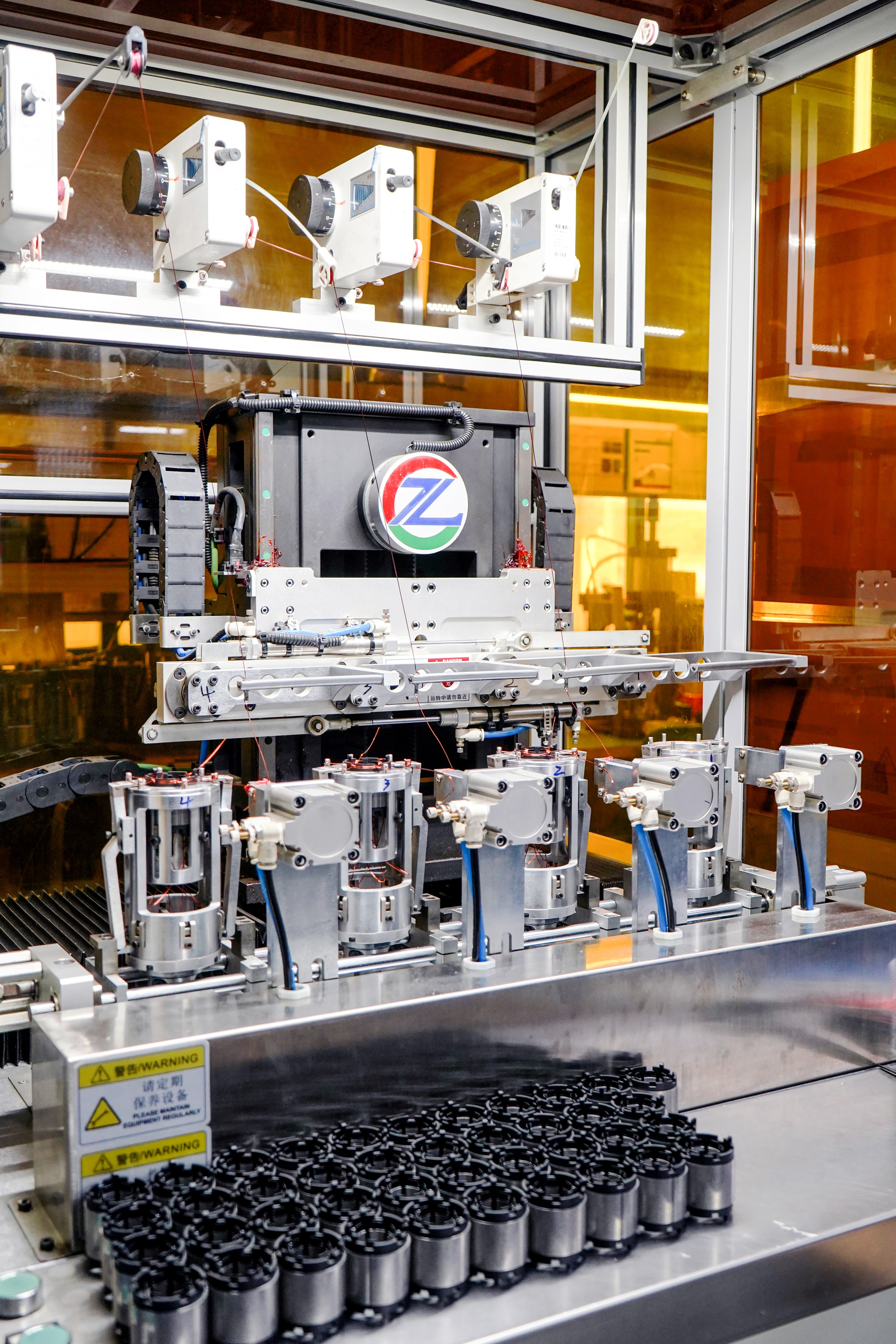
On the supply side, the pressure is toward verifiable consistency. Motor performance is the product of winding, magnet, gear machining, and assembly control, and miniature motor suppliers that operate in-house winding, gear measurement, and life testing can document those steps rather than assert them. TT Motor (Shenzhen) Industrial Co., Limited, a China-based manufacturer of miniature precision motors established in 2006 and headquartered in Bao'an District, Shenzhen, Guangdong Province, states 35 engineers working on motor design and motor structure optimization, an annual output of 8,000,000 pieces, and export activity concentrated in the EU and USA markets, with miniature motors used across industrial automation, intelligent robots, medical equipment, precision instruments, smart homes, automotive electronics, and unmanned equipment.
For buyers, the useful conclusion is procedural. Efficiency regulation will continue to tighten for large industrial machines, but miniature drive selection will remain an application-level decision driven by duty cycle, maintenance economics, and control integration. The teams that decide well are the ones that define verification criteria early, rather than the ones that choose the most advanced-sounding motor category.
FAQ
- What does rated torque mean on a brushless gear motor datasheet, and what load can one motor handle?
- Rated torque is the torque that can be continuously output under specified operating conditions, so it should be read as a continuous value rather than a peak capacity. Load capacity differs between motor models and is defined against the stated conditions: a 36 mm brushless planetary gear motor is specified at a maximum rated torque of 30.0 kg.cm, while a DC brushless worm gear motor in the same portfolio is specified at a maximum rated torque of 8.0 kg.cm at 3 to 35 rpm. Because requirements vary by application, load capacity is normally matched per project rather than drawn from a single category figure.
- Which is more suitable for long-term continuous operation, a brushless motor or a brushed motor?
- For equipment requiring long-term continuous operation, high speed, or low maintenance, brushless motors are generally recommended. Brushless motors use electronic commutation and have no traditional brushes or commutator, which reduces mechanical wear and gives advantages in lifespan, efficiency, noise, and maintenance. Brushed motors experience frictional losses, are commonly described as having a service life in the range of several hundred to several thousand hours, and produce sparks and carbon dust that create stronger electromagnetic interference. The trade-off is that brushed motors cost less initially and are simpler to control, while brushless motors cost more upfront but require virtually no maintenance.
- What are the advantages of an integrated geared motor compared with a separate motor and external gearbox?
- An integrated geared motor combines the motor and gearbox so that lower speeds and higher output torque are achieved within a more compact space. Compared with a motor plus external gearbox arrangement, integrated units typically have a more compact structure, are easier to install, require fewer couplings and mounting structures, simplify power matching, and help reduce overall machine space and assembly costs. They are usually recommended when equipment space is limited and the budget is constrained.
- How can buyers avoid the situation where samples are qualified but batch products perform inconsistently?
- The standard approach is procedural. Before mass production, define the motor parameters and acceptance standards, conduct small-batch trial production first, establish a shipment inspection mechanism, and then proceed to volume production. If the supplier changes raw materials, components, or production processes, the customer should be notified in advance and the process re-verified. The known triggers for inconsistency are replacement of raw materials or components, failure to lock in the sample process during mass production, sample quantities too small to reflect batch consistency, changes in production equipment or mold condition, and inadequate parameter control between batches.
- Can RoHS test reports be provided for miniature DC motors?
- Most miniature motors in the reference portfolio have passed RoHS testing, with reference to RoHS Directive (EU) 2015/863 amending 2011/65/EU. Because declarations are issued at model and material level rather than at product category level, buyers should request the report for the exact model and material combination being sourced, and confirm which substances and thresholds the document covers.
Reference Material
Product and company information in this article is drawn from published supplier specifications and application records for the GMP36-TEC3650 brushless planetary gear motor, the TWG3246-TEC2430 DC brushless worm gear motor, the GM12-N20VA DC spur gear motor, and the GM37-555PM DC gear motor. Market and regulatory data are attributed to Grand View Research, Precedence Research, OEC trade data, the IEC 60034-30-1:2025 standard, and EU Ecodesign Regulation (EU) 2019/1781. A downloadable brochure covering the miniature motor product lines is available at https://cdn.socialarks.com/sbsp/25192/common/2026/0821/%E5%B1%95%E4%BC%9A%E5%AE%A3%E4%BC%A0%E5%86%8C.pdf, and the manufacturer website is www.ttmotor.com.