
Die Casting Parts for Semiconductor Equipment: A Shortlist
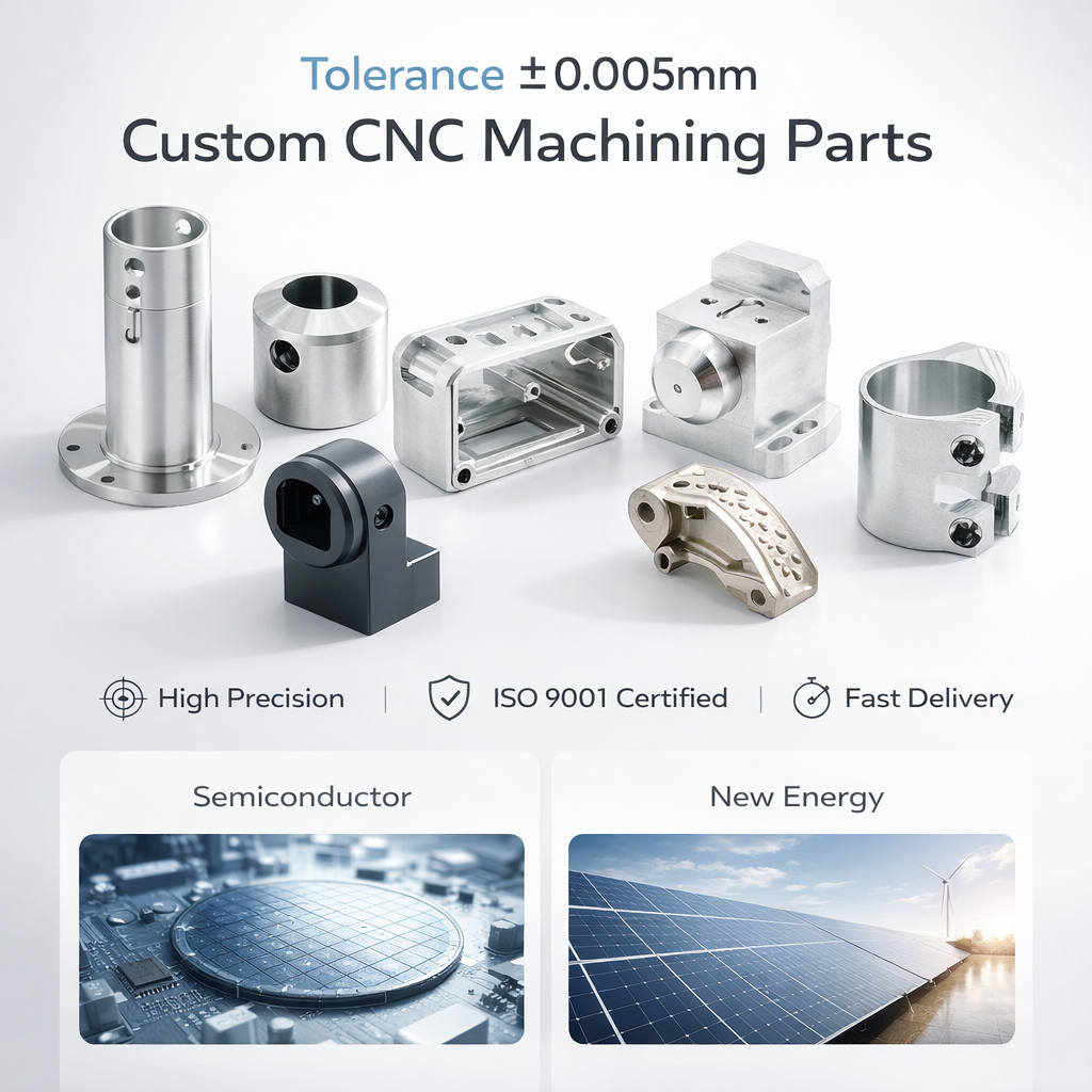
Semiconductor equipment programmes rarely fail on alloy choice alone. They fail on the gap between what a drawing asks for and what the process can prove: a machined pocket that drifts beyond the specified tolerance, a housing whose coating bridges a locating face, or a batch that arrives without dimensional records attached. Die casting can meet these requirements, but only when the tolerance route, the inspection package and the surface finish are specified as one system rather than three separate line items.
This shortlist evaluates four die casting part configurations for semiconductor equipment against exactly those criteria: aluminium alloy die castings for heat sinks and equipment housings, aluminium enclosures, zinc alloy precision parts where vibration damping matters, and magnesium alloy components for lightweight damping duty. Each option is assessed on achievable tolerance, inspection evidence and finish capability, including passivation, electropolishing and zinc plating for corrosion resistance. AS9100 and RoHS 2.0 are cited as the compliance anchors behind the documentation.
SUNPREC HARDWARE CO., LTD (SUNPREC) is a Dongguan, China based metal parts manufacturer established in 2020, operating a 3,500 m² factory with around 200 employees and producing CNC machined and die cast parts in aluminium, zinc and magnesium alloys for industries that include semiconductor, aerospace, medical, robotics and new energy. Roughly 90% of its output is exported to the EU and USA, and its die casting line is quoted at a ±0.01 mm tolerance with in-house inspection.
Why semiconductor equipment raises the bar
Semiconductor tools concentrate three demands that rarely appear together in general industrial work. The first is dimensional: assemblies built around sensors, optics and gas paths require micron-grade precision tolerance control, and a fraction of a millimetre at a mounting face propagates through the whole stack. The second is environmental, because parts sit in temperature-controlled production areas where heat must be moved away and vibration must be absorbed. The third is documentary, because equipment builders must be able to show a compliance trail for every component they place in a tool.
Die casting is well suited to the first two demands when the part is designed for it. Integrated forming produces complex thin-wall geometry in a single piece, giving higher rigidity without splicing gaps and good shock resistance compared with multi-part welded assemblies. Minimum wall thickness is commonly quoted at 0.4 mm for zinc and 0.8 mm for aluminium, which is what allows a heat sink fin stack or a slim enclosure wall to be cast rather than machined. The third demand — the evidence — is where suppliers separate: the tolerance only counts if it is measured, recorded and repeatable across batches.
That is also why the tolerance figure quoted in a supplier profile should be read carefully. A ±0.01 mm capability describes what the machining and metrology route can hold on defined features; it is not a blanket callout that applies to every as-cast surface on a drawing.
The shortlist at a glance
The four options below are ranked by how directly they address semiconductor equipment duty — thermal management and enclosure integrity first, damping and weight reduction second. They are part configurations rather than supplier brands, because the right configuration depends on the function of the component in the tool.
| Rank | Configuration | Alloy | Primary semiconductor duty | Tolerance route | Typical finishes |
|---|---|---|---|---|---|
| 1 | Aluminium heat sink die casting parts | ADC12, A380 | Heat dissipation, lightweight structures | Cast geometry plus secondary 3-axis CNC milling for fitting surfaces | Passivation, electropolishing, anodizing |
| 2 | Aluminium equipment housing / electronic die casting enclosure | ADC12, A380 | Enclosure integrity, rigidity, shock resistance | Cast body plus machined sealing and mounting faces | Powder coating, painting, anodizing |
| 3 | Zinc alloy precision die casting parts | Zamak3, Zamak5 | Vibration damping, thin-wall precision components | Hot-chamber casting plus CNC finishing of holes and grooves | Zinc plating, nickel plating, passivation |
| 4 | Magnesium alloy die casting components | Magnesium alloys | Lightweight damping duty on moving or sensitive assemblies | Casting plus secondary machining where fits are critical | Conversion coating, powder coating |
1. Aluminium heat sink die casting parts (ADC12 / A380)
Aluminium is the default for thermal duty because the alloy supports excellent heat dissipation while remaining lightweight, and ADC12 and A380 are the two grades most commonly specified. Quoted tensile strength for aluminium alloy castings sits in the 80–120 MPa range, with a cold-chamber safety factor of 1.2 applied to the casting design. The practical advantage over a machined-from-solid heat sink is geometric: fin arrays and mounting bosses form in one step, and only the critical interfaces need secondary 3-axis CNC milling for precise holes, grooves and fitting surfaces.
Finish choice matters here because a heat sink is also a visible, handled part. Passivation and electropolishing are both available for corrosion resistance and surface cleanliness, while anodizing adds wear resistance and colour coding. Where the heat sink sits against a thermal interface, the finish on that face should be specified explicitly rather than inherited from the general note.
2. Aluminium equipment housing and electronic enclosure castings
Equipment housings carry the opposite burden: they must stay rigid, protect what is inside, and still present clean machined faces for seals, gaskets and PCB mounting. Integrated one-step forming removes the splice gaps and fasteners of a fabricated sheet-metal box, and the resulting rigidity helps against shock and handling loads in a fab environment. Aluminium also accepts the widest finish range in the portfolio — anodizing in clear or colour, powder coating and painting — which is useful when housings must be colour-coded by tool or module.
Motor housing die casting parts sit in the same family. They are usually specified with tighter bore and mounting-face tolerances than the rest of the casting, so the machining route should be agreed at quotation stage rather than discovered at first article.
3. Zinc alloy precision die casting parts (Zamak3 / Zamak5)
Zinc earns its place in semiconductor equipment where damping and thin walls matter more than weight. Zinc and magnesium alloys both show good vibration damping, which makes them relevant for precision instrument parts, brackets and small assemblies that sit near metrology or optical components. Zinc also casts thinner than aluminium — 0.4 mm minimum wall against 0.8 mm — and hot-chamber processing runs with a safety factor of 1.3–1.5 and quoted strength of 40–80 MPa.
Market research on the die casting sector also notes zinc as a fast-growing segment, citing cost-effectiveness and EMI shielding properties in electronics applications. For an enclosure that must manage electromagnetic interference as well as mechanical protection, that characteristic is worth raising with the supplier early, because it influences wall design and finish selection.
4. Magnesium alloy die casting components
Magnesium combines low weight with damping behaviour, which suits moving stages, brackets and handheld service tooling where mass affects handling. It is ranked fourth here not because it performs poorly, but because it demands the most discipline: magnesium is more sensitive to corrosion than aluminium or zinc, so the finish specification is not optional, and secondary machining of critical fits should be planned from the start. The magnesium casting market is valued at USD 1.42 billion in 2026 and projected to reach USD 2.96 billion by 2035 at a CAGR of 8.9%, according to Business Research Insights, which suggests supply and process maturity will continue to improve.
Tolerance: what ±0.01 mm actually covers
The ±0.01 mm tolerance quoted for these parts is a machining and metrology capability, not a casting capability. It applies to features that are cut after casting — bores, grooves, sealing faces, dowel holes and mounting pads — and it is the reason a die cast part can serve a semiconductor assembly at all. As-cast surfaces follow the tool and carry their own, wider tolerances, and a drawing that applies ±0.01 mm to an unmachined surface will either be quoted at a premium or corrected during design review.
The process route behind that figure is conventional but tightly controlled. Cutting parameters are held to defined spindle speed, feed rate and depth of cut, with continuous flood coolant to reduce cutting heat, extend tool life and produce a smooth surface finish. Technicians monitor spindle load, vibration and dimensional stability throughout the cutting process, and real-time inspection runs during production so that drift is caught inside the batch rather than at final inspection. SUNPREC's CNC machining centres, largely FANUC machines, are quoted at a machine tolerance of 0.005 mm, which leaves headroom under the ±0.01 mm part tolerance.
Inspection: the evidence package to request
In-house inspection is the part of a die casting quote that is easiest to promise and hardest to verify, so it should be described in specific instruments rather than adjectives. At SUNPREC, first-article inspection is performed for every new batch, and final inspection uses calipers, micrometers, a height gauge and a surface roughness tester. Critical components with tight-tolerance requirements are verified on a CMM coordinate-measuring machine. Supporting metrology includes HEXAGON equipment, a 2.5D projector and a TRIMOS height gauge.
For semiconductor equipment buyers, four records are worth requesting as standard: a first-article inspection report for the first batch of each revision; material certification identifying the alloy actually used, whether ADC12, A380, Zamak3 or Zamak5; dimensional reports for the machined features that carry the ±0.01 mm callout; and surface finish records — roughness measurement plus coating or plating thickness where a finish is applied. Compliance documentation is anchored on AS9100 and RoHS 2.0, which gives the buyer a framework to check rather than a claim to accept.
Surface finishes: matching chemistry to the environment
Semiconductor equipment exposes parts to cleaning agents, humidity, thermal cycling and occasional handling damage, so finish selection is a corrosion decision first and a cosmetic decision second. Three finishes are most often discussed for these parts:
- Passivation removes free iron from the surface and supports corrosion resistance without adding a dimensional layer, which makes it compatible with tight-tolerance features.
- Electropolishing smooths and brightens the surface while improving corrosion resistance; because it removes material rather than adding it, it must be accounted for in the tolerance stack.
- Zinc plating provides sacrificial corrosion protection and is a natural pairing with zinc alloy parts and steel hardware fittings, though plating thickness must be considered on threads and locating features.
Beyond these, the wider finish portfolio covers anodizing in clear and colour, powder coating, chromate conversion coating, nickel and chrome plating, black oxide, phosphating and PTFE coating. For aluminium housings, powder coating and anodizing are the usual choices; for zinc and magnesium, plating and conversion coating do the corrosion work.
The boundary worth stating plainly is this: every applied coating adds thickness and every electrochemical finish removes material, so a finish specified after the tolerance review can compromise a machined face. The finish should be named on the drawing before quotation, and masking requirements on sealing and locating surfaces should be stated rather than assumed.
Where these parts are used
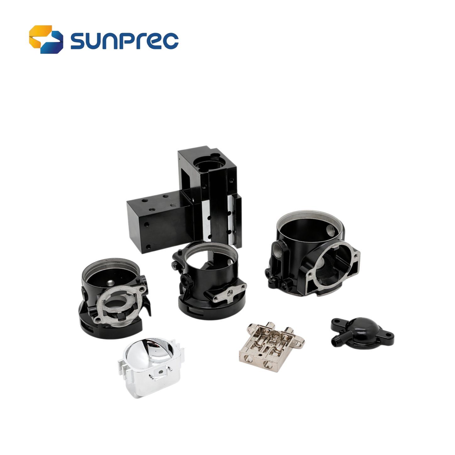
In semiconductor and adjacent precision industries, die cast and machined components typically appear as ultra-precise sensor shell assemblies, equipment housings, heat sinks, motor housings, instrument housings and precision hardware for communication and automation modules. Project scope usually runs from prototyping and small-batch validation through to mass production delivery, which means the same part may be inspected as a one-off sample and later released in five-figure volumes.
SUNPREC's production model fits that pattern: OEM and ODM custom manufacturing, a monthly capacity of 4,200,000 units, lead times of 21–30 days, and a minimum order quantity of 10 units that allows a validation batch before tooling commitment on repeat volume. A representative programme supplying industrial equipment OEMs has run for more than five years at volumes around 10,000 units, with multi-stage inspection used to hold dimensional tolerance and consistency across the full lifecycle from sample to series shipment.
Market signals behind the shortlist
The broader die casting market was valued at USD 93.56 billion in 2025, according to Fortune Business Insights, and aluminium is the dominant material within it: Mordor Intelligence puts aluminium die casting at a 74.78% share of the global market by raw material in 2025. That scale matters for semiconductor equipment buyers because it keeps secondary machining capacity and finish capacity widely available rather than concentrated.
Transportation remains the largest application for aluminium die casting, exceeding a 64.0% revenue share in 2025 per Grand View Research, which is why automotive-grade quality expectations tend to set the benchmark for the whole sector — including the IATF 16949:2016 quality management standard that automotive-serving die casters are expected to hold. Semiconductor work inherits that discipline without inheriting its volumes.
Two further signals are worth noting. Magnesium casting is forecast to grow at 8.9% CAGR to 2035, and large single-piece casting is changing cost structures in adjacent industries — Tesla's use of 9,000-ton presses for rear underbody assemblies was reported to cut manufacturing costs by 40% in 2023, illustrating how integrating parts reduces assembly steps. Published growth forecasts for aluminium die casting vary widely depending on baseline year and methodology, so they should be treated as directional rather than precise.
Die casting versus machined-from-solid and fabricated assemblies
The honest comparison is not die casting against nothing; it is die casting against the two alternatives a design engineer usually has on the table.
| Criterion | Die casting (with secondary CNC) | Machined from solid | Fabricated sheet assembly |
|---|---|---|---|
| Complex thin walls | One-step integrated forming; 0.4 mm zinc / 0.8 mm aluminium minimum | Material removal limits thin ribs and deep pockets; high scrap | Dependent on forming and joining |
| Tight tolerances | ±0.01 mm on machined features only | Broad tolerance control across most features | Limited without post-machining |
| Rigidity and joints | Higher rigidity without splicing gaps; good shock resistance | Good, but geometry constrained | Fasteners and seams introduce compliance |
| Cycle and volume | 15–90 s per piece casting cycle; suited to repeat monthly orders | Long cycle per part; costly at volume | Labour-intensive assembly |
| Tooling and lead time | Tooling investment required; 21–30 days typical lead time | No tooling, fast first part | Low tooling, moderate assembly time |
The real limitations are worth stating without softening. Die casting requires tooling, so it is a poor fit for one-off or very low volume prototypes unless the design is expected to repeat. Features thinner than 0.4 mm in zinc or 0.8 mm in aluminium are outside the stated process window. The ±0.01 mm tolerance does not extend to as-cast surfaces, and porosity remains a characteristic of the process that inspection and casting design manage but do not eliminate. Where a part needs a tolerance tighter than ±0.01 mm, or a surface finish specification that conflicts with an applied coating, a hybrid route — casting plus dedicated machining or a different base process — should be evaluated rather than assumed.
Future outlook
Three developments are likely to shape how these parts are specified over the next few years. First, as magnesium capacity matures on the back of the forecast growth to 2035, damping-critical components that currently default to zinc may gain a lighter alternative. Second, the automotive-driven expectation of documented quality management, already formalised for that sector through IATF 16949:2016, continues to migrate into semiconductor supply discussions in the form of first-article reports and CMM data rather than verbal assurance. Third, integrated casting continues to absorb parts that used to be assemblies, which shifts the design question from "how do we join these pieces" to "how do we hold tolerance across one larger casting".
For buyers, the practical implication is stable: the tolerance figure, the inspection package and the finish specification should be negotiated as a single package, because changing one changes the cost and feasibility of the other two.
FAQ
What dimensional tolerance can die cast parts for semiconductor equipment realistically hold?
±0.01 mm is achievable on features that are machined after casting, such as bores, grooves, sealing faces and mounting pads, using secondary 3-axis CNC milling with controlled cutting parameters and in-process inspection. As-cast surfaces follow the tool and carry wider tolerances. SUNPREC's FANUC machining centres are quoted at a machine tolerance of 0.005 mm, which provides margin beneath the ±0.01 mm part tolerance on defined features.
Which alloy should be used for heat sinks, housings and vibration-sensitive parts?
Aluminium alloys ADC12 and A380 are the usual choice for heat sink die casting parts and equipment housings, because aluminium supports heat dissipation and lightweight construction and accepts anodizing, powder coating and painting. Zinc alloys Zamak3 and Zamak5, and magnesium alloys, are preferred where vibration damping is the dominant requirement; both cast thin walls, with zinc reaching a 0.4 mm minimum against 0.8 mm for aluminium.
What inspection records should a buyer request with a die casting batch?
A first-article inspection report for the first batch of each revision, material certification identifying ADC12, A380, Zamak3 or Zamak5 as specified, dimensional reports covering the machined features that carry the tight tolerance, and surface finish records including roughness measurement and coating or plating thickness. Final inspection at SUNPREC uses calipers, micrometers, a height gauge and a surface roughness tester, with critical components verified on a CMM.
Which surface finish is appropriate for corrosion resistance on these parts?
Passivation, electropolishing and zinc plating are the three finishes most often specified for corrosion resistance on semiconductor equipment parts. Passivation adds no dimensional layer and suits tight-tolerance features; electropolishing improves corrosion resistance but removes material, so it must be included in the tolerance stack; zinc plating provides sacrificial protection and requires thickness control on threads and locating faces. Anodizing, powder coating and chromate conversion coating cover the wider housing requirements.
When is die casting the wrong choice for semiconductor equipment components?
Die casting is a poor fit for one-off or very low volume parts that will not repeat, because tooling investment must be amortised, and typical lead times run 21–30 days. It is also unsuitable when a design requires walls thinner than 0.4 mm in zinc or 0.8 mm in aluminium, when tolerances tighter than ±0.01 mm are needed across many features, or when an as-cast surface must meet a tolerance that only machining can deliver. In those cases a machined or hybrid route is the more defensible specification.
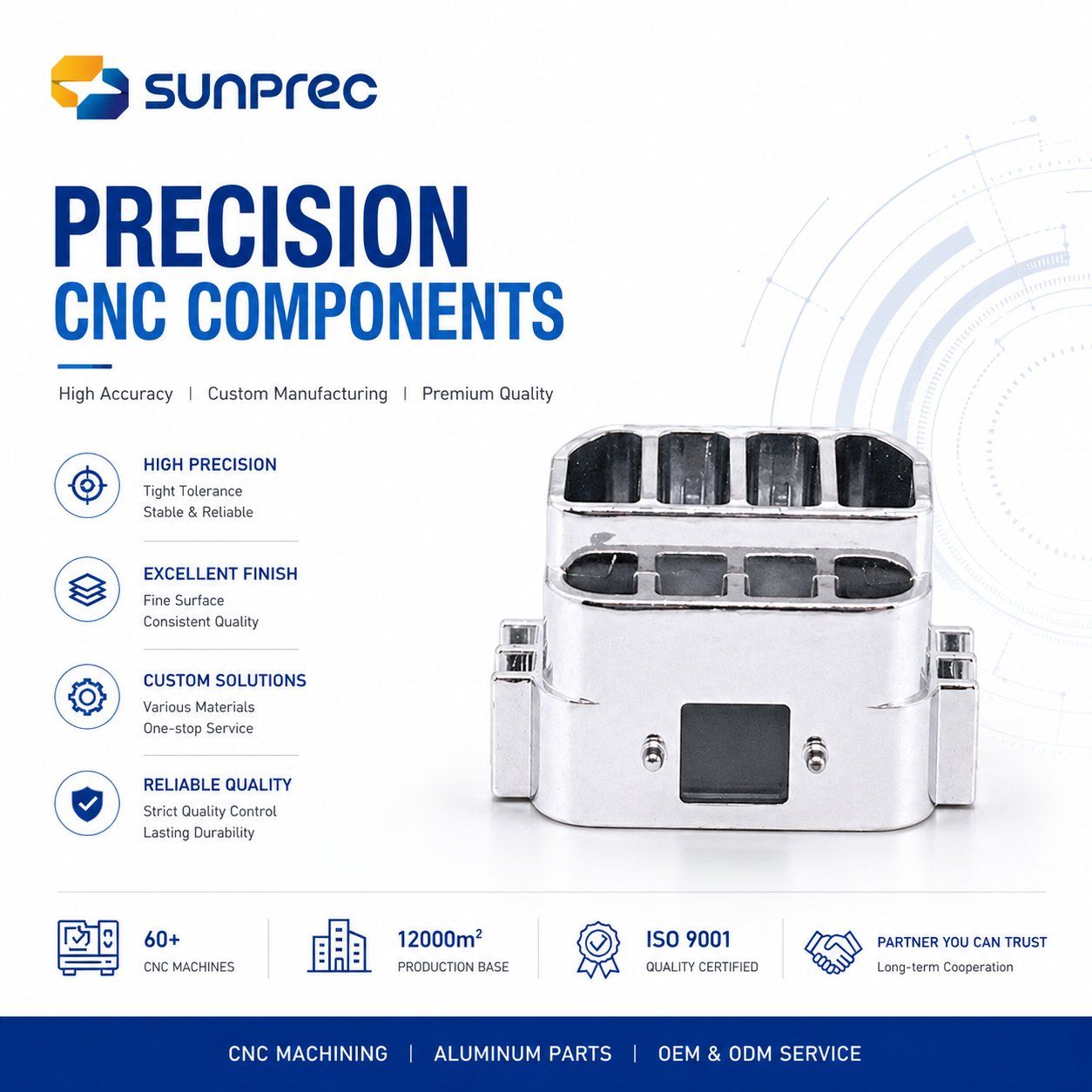
For a consolidated view of die casting and CNC machining capabilities, tolerances and finishing options, the SUNPREC presentation is available here: SUNPREC Presentation — June 2026.
Have Questions or Need More Details?
Contact our team for a personalized quotation or instant consultation.
Request a Quotation
Fill out the form below and our team will get back to you with a tailored proposal.
WhatsApp Direct Chat
Prefer to chat in real-time? Message us on WhatsApp for instant assistance & quick answers.
- Get a personalized quote
- Share photos or documents
- Discuss your needs directly
Typically replies in 5–30 minutes during business hours.