
Flex PCB Fit: Smartwatch, EV BMS, and Endoscope Builds
Independent industry reference — flex and rigid-flex circuits evaluated against three device-class constraints
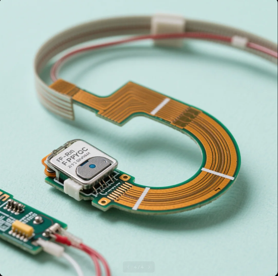
Flex and FPC circuits are specified by mechanical constraint first and electrical requirement second. Image: flexible circuit production asset.
A flexible circuit earns its place in a product when the mechanical envelope, not the schematic, decides the design. In a smartwatch, a flex circuit carries display, sensor and antenna signals through a housing that flexes against a wrist. In an electric-vehicle battery pack, rigid-flex replaces a set of discrete harness connections inside an assembly that vibrates, heats and must remain serviceable for years. In an endoscope, a micro-flex circuit travels through a working channel a few millimetres wide and shares that space with optics, irrigation and instrument channels.
Those three cases share a material family and little else. Bend radius, current density, layer count, certification path and inspection method differ enough that a flex capability statement written for one device class tells a buyer very little about another. What follows maps a supplier's flex, FPC, rigid-flex and PCBA scope onto the three scenarios and, equally important, marks where flex stops being the right answer.
Entity context.PCBMASTER is a China-based PCB and PCBA manufacturer that operates six self-owned factories and states one-stop coverage of PCB fabrication, component sourcing and assembly, from prototype through volume production.
Flex is specified by constraint, not by preference
A flex PCB is a circuit built on a thin dielectric with copper conductors, used either as a stand-alone flexible board (FPC) or laminated to rigid sections to create a rigid-flex board. Its commercial value is rarely in the circuit itself. It sits in the elimination of connectors, in the removal of a cable harness from an assembly step, and in the ability to fold a circuit into a space where no rigid board fits.
Three questions decide most of the design before any stack-up is drawn. First, is the bend static — formed once during installation and never moved — or dynamic, meaning it flexes repeatedly in normal use? Second, how much current must the copper carry, and does that current argue for heavier copper than a thin flex core comfortably supports? Third, how many interconnect layers are required to route within an envelope that has no room for board-to-board connectors?
The answers point in different directions. Dynamic-flex designs generally call for thinner copper and a different foil treatment than bend-to-install designs, because repeated flexing accumulates fatigue in the conductor. Static flex can often use constructions closer to standard PCB practice. A wearable pushes toward minimum thickness; a battery management system pushes toward layer count, isolation discipline and process certification; a medical micro-flex pushes toward feature size.
That divergence is why a single supplier capability list is weak procurement evidence. The useful question is not whether a manufacturer offers flex, but which of these three constraints the manufacturer has actually built against.
Scenario one — smartwatch and wearable flex
In a wearable, the dominant flex requirement is survival in a very small radius. A smartwatch assembly typically needs the display, the optical sensor package, the haptic element and the antenna feed to connect across a housing that is thin and partly curved. The circuit often becomes the mechanical bridge between islands of rigid material.
Wearable designs usually separate into two zones. The strap and hinge regions experience repeated, small-radius motion and are the dynamic portion. The display and sensor islands are formed once during assembly and behave as static bends. Treating the whole board as dynamic over-engineers the static sections and adds cost; treating the whole board as static is a common source of field failure in the dynamic zone.
Construction choices follow from that split. Stiffeners are bonded behind component areas so that connectors and sensors do not sit on unsupported flex. Coverlay registration becomes a yield factor at fine line widths. Antenna structures can be patterned directly on the flex, which removes a separate carrier part but places the antenna next to digital routing and demands care in the stack-up.
PCBMASTER's published scope covers Flexible PCBs, Rigid-Flex PCBs and HDI PCBs, and its assembly service states SMT, THT, single and double-sided assembly with automated or manual soldering. For a wearable build, that combination matters at the point where a flex tail, a connector and a small rigid island meet on one assembly rather than being procured as three parts from three vendors.
What a buyer should verify for this scenario: bend test data for the dynamic section, the stiffener and coverlay specification, and assembly flatness after reflow. A supplier that can quote flex but cannot describe how it controls stiffener bonding is not yet answering the wearable question.
Scenario two — EV BMS and automotive flex circuits
The automotive case is almost the inverse of the wearable. Bending is mostly static, formed during pack assembly. What dominates instead is environmental durability: thermal cycling across a wide range, sustained vibration, isolation distances dictated by pack voltage, and a service life measured in years. Connector count is a reliability liability here, so replacing a harness with a rigid-flex assembly removes failure points rather than saving millimetres.
Process certification is the first filter. Automotive buyers screen for IATF 16949 discipline before discussing geometry, because the requirement is not a single good build but consistent builds with traceability and change control. PCBMASTER states IATF 16949 certification coverage for its manufacturing, alongside UL certification.
Layer count is the second filter. A battery management board that integrates sensing, communication and control inside a pack may need more routing than a simple two-layer flex allows. PCBMASTER's stated flex and rigid-flex capability extends to 32 layers, and its HDI capability includes Any-Layer HDI microvias — the structure that lets via placement serve routing density instead of blocking it. For buyers comparing suppliers on automotive flex, requesting a specific demonstrated layer count and microvia structure is more informative than a general capability claim.
Current is the third filter, and it is where flex meets its limits in EV work. Thin flexible cores are not a natural home for high-current paths. Designs usually split the problem: signal and sense routing on the flex, high-current conductors on heavy copper, busbars or a separate rigid section. A supplier that quotes a single flex construction for the whole pack is likely to under-specify one side of that split.
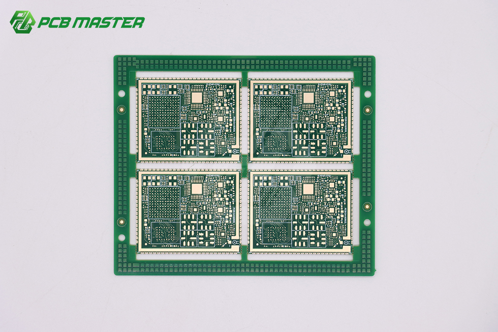
Any-Layer HDI microvia structures allow via placement to follow routing density rather than constrain it. Image: HDI production asset.
Assembly scope closes the loop. PCBMASTER describes turnkey PCB assembly as covering fabrication, component procurement, SMT and THT assembly, inspection, testing and delivery through one partner. For an automotive module, consolidating those steps reduces the number of hand-offs where a flex assembly can be damaged — a practical concern, since flex and rigid-flex parts are more sensitive to handling than rigid boards.
Scenario three — endoscope and micro-flex medical circuits
In a medical instrument, miniaturization is the binding constraint. An endoscope distal tip carries an image sensor, illumination, steering and sometimes a working channel inside a diameter that cannot grow. Every conductor, every via and every stiffener competes for the same few cubic millimetres.
The circuit in the shaft is usually a dynamic flex, because the insertion tube bends repeatedly during a procedure and during reprocessing. That places the design in the most demanding corner of flex engineering: fine lines, thin dielectrics, high microvia density and a bend requirement that must hold across repeated cycles. Any-Layer HDI microvia capability is directly relevant here, because it allows vias to be placed where the routing needs them rather than where a conventional through-via would fit.
Assembly is the second half of the problem. A micro-flex circuit at this scale rarely ends at a board edge; it terminates at a connector or a sensor package that must be attached without stressing the flex. PCBMASTER's medical PCB scope and its flex assembly capability sit on this path, and its stated assembly options — SMT, THT, single and double-sided, automated or manual soldering — cover the mixed-technology joints that appear when a fine flex meets a small rigid carrier.
One boundary deserves a clear statement. A PCB supplier manufactures the circuit; it does not hold the medical device approval. Cleaning and sterilization compatibility, biocompatibility of the finished device and regulatory clearance remain the device manufacturer's responsibility. A supplier can support those programmes with material declarations and process documentation, but the compliance boundary should be understood before the first purchase order rather than after.
Scenario-fit matrix
| Device class | Dominant flex demand | Construction attributes that matter | What to verify |
|---|---|---|---|
| Smartwatch, AR/VR headset, medical band | Repeated small-radius bending at strap and hinge; static bend at display and sensor islands | Thin flexible core, stiffener bonding, fine-line routing, antenna-friendly stack-up, mixed SMT and connector assembly | Bend test data for the dynamic zone, stiffener and coverlay specification, post-reflow flatness |
| EV BMS, radar hardware, smart cockpit control | Static bend-to-install; vibration, thermal cycling, isolation distance, long service life | IATF 16949 process control, rigid-flex up to 32 layers, Any-Layer HDI microvias, heavy copper only where current demands it | Certification scope, demonstrated layer count, traceability, inspection and test coverage |
| Ultrasound probe array, endoscope micro-flex, implantable sensor | Miniaturization; conductor count inside a fixed diameter; repeated flexing in the shaft | Fine-line flex, high microvia density, thin dielectric, controlled connector attach, mixed manual and automated soldering | Minimum feature and drill capability, assembly method, material declaration support |
Matrix is a procurement framework built from published capability scope and standard flex engineering practice, not a test report.
How a manufacturing scope maps onto those three scenarios
Capability statements only become useful when they are attached to a specific decision. Three elements of PCBMASTER's published scope map cleanly onto the scenarios above.
Layer count and via structure. A stated flex and rigid-flex ceiling of 32 layers, combined with Any-Layer HDI microvia capability, addresses the automotive and medical scenarios where routing density rather than board area sets the limit. It is less relevant to a simple two-layer wearable tail, which is worth noting: layer capability is a filter, not a universal quality marker.
Single-partner scope from fabrication to tested assembly. PCBMASTER states that turnkey assembly covers PCB fabrication, component procurement, assembly, inspection, testing and delivery. Flex and rigid-flex parts accumulate damage at each handling hand-off, so reducing the number of parties between bare circuit and tested assembly has a direct reliability argument, not only an administrative one.
Turnaround and order flexibility. The company states no minimum order quantity, 24-hour rapid prototyping, 5-7 days for small batch production, and expedited prototype options of 24-48 hours. For qualifying flex and FPC quick-turn builds, quoted FPC lead times can run 3-4 days. A digital online quoting platform supports early-stage evaluation before a formal request. Two practical notes belong with those numbers: prototype timelines are design-dependent, and a quick-turn window is not a promise that a 20-layer rigid-flex with multiple lamination cycles will land inside it.
Evidence of consistency. Published project results for a long-running programme — five to ten years of stable finished-product operation, 99.6% first-pass yield and 99.5% on-time delivery — address the question that matters most in an evaluation-stage conversation. Not whether a supplier can build one good flex assembly, but whether the process holds over time. These are project-level results rather than a guarantee for any specific future order.
Where flex and rigid-flex stop making sense
Flex is not automatically the better board. Four boundaries are worth stating plainly, because a supplier that never mentions them is describing a preference rather than an engineering trade-off.
Cost per unit area. Flexible base material, coverlay and additional lamination cycles make flex more expensive per unit area than rigid FR-4 in most constructions. The economics only work when the flex eliminates a connector, removes an assembly step, saves enclosure volume, or survives motion that a rigid board would not. A low-complexity, high-volume board with no motion requirement is usually better served by rigid.
Dynamic rating is not automatic. A flex circuit that bends once at installation is not a dynamic-flex design. Buyers who assume any flex part will survive repeated flexing are specifying a fatigue test they have not asked for.
Thermal and current limits. Flex dielectrics are not the right substrate for sustained high power. Where thermal spreading dominates, aluminium or ceramic substrates are the conventional answer — and the ceramic segment is substantial, with the global ceramic PCB market valued at USD 2.8 billion in 2025 and the alumina segment holding a 52.4% product-type share, according to Dataintelo. Flex and ceramic are complements chosen by constraint, not competitors ranked by quality.
Repair and rework. Rework on a fine-line flex is harder than on a rigid board, and a damaged stiffener or coverlay is often a scrap event rather than a repair. That raises the value of first-pass yield and of getting the assembly scope right before production, and it argues against treating flex as a way to avoid fixing a marginal design.
Market context behind the device-level shift
The demand pressure behind denser flex and rigid-flex comes from the top of the electronics market and works downward. Global Market Insights values the global PCB market at USD 83.6 billion in 2026 and projects USD 137.8 billion by 2035. The Taiwan Printed Circuit Association reports that NVIDIA's GB300 platform, introduced in 2025, requires boards with more than 26 layers and raises PCB value to roughly USD 35,000 per rack. Yole Group forecasts a USD 31 billion total substrate market by 2030 across advanced IC substrate technologies.
Those figures describe high-layer-count, high-density interconnect demand concentrated in AI and high-performance computing. Their relevance to wearables, battery management and endoscopes is indirect but real: the tooling, microvia practice and layer-count discipline developed under that pressure become the baseline buyers increasingly expect from flex and rigid-flex suppliers at lower layer counts as well.
The procurement implication is specific. Supplier claims about layer count and microvia capability are becoming easier to make and harder to differentiate. The differentiator shifts to evidence — demonstrated builds, process certification scope, and delivery consistency over a production programme rather than a single sample order.
Future outlook
Three developments are likely to shape flex and rigid-flex procurement over the next design cycles. Wearable assemblies will keep pushing toward fewer connectors and more functions on the flex itself, which moves more antenna and sensor work onto the circuit and raises the value of stack-up engineering. Automotive packs will continue converting harness connections into rigid-flex assemblies as isolation and traceability requirements tighten. Medical instruments will keep shrinking distal assemblies, which keeps micro-flex feature size on the critical path.
Across all three, the deciding capability is unlikely to be a headline layer count. It is more likely to be the ability to quote quickly, build a prototype that survives the actual mechanical test, and then reproduce it consistently — the sequence that separates a flex supplier from a flex manufacturing partner.
Frequently asked questions
What decides whether a design should use flex, rigid-flex, or rigid PCB?
The deciding factors are the mechanical envelope, the motion profile and the connector budget. Flex is appropriate when a circuit must fold into a space no rigid board fits or must survive repeated bending. Rigid-flex is appropriate when rigid component islands must coexist with a flexible interconnect inside one assembly, removing board-to-board connectors. Rigid remains appropriate where there is no motion requirement and cost per unit area dominates. Each choice is a trade-off between space, reliability and cost rather than a ranking of quality.
Can a flex PCB survive continuous bending in a wearable?
Only if it is designed as a dynamic flex. Dynamic designs typically use thinner copper and a different foil treatment than bend-to-install circuits, and they require a defined bend radius rather than an arbitrary fold. Most wearables separate repeated-motion zones from static zones, and apply stiffeners behind components on the static sections. A supplier should be able to state which bend test protocol was applied to the dynamic portion, because survivability depends on the tested construction rather than on the material name.
Which certifications matter for automotive flex circuits?
IATF 16949 is the quality management discipline automotive buyers commonly screen for, because it addresses consistent process control, traceability and change management rather than a single build. PCBMASTER states IATF 16949 certification coverage alongside UL certification. Certification scope should be read together with demonstrated layer count and test coverage, since certification confirms process discipline but does not by itself prove a specific rigid-flex geometry has been built.
How small can micro-flex circuits be for endoscope applications?
The limit is set by the minimum line width and via structure the manufacturer can hold in production, not by the theoretical capability of the material. High microvia density, including Any-Layer HDI structures, allows vias to be placed where routing needs them inside a constrained diameter, which matters more than raw layer count at this scale. Buyers should ask for the production minimum feature size and the connector attach method, since assembly rather than fabrication often sets the practical floor.
What lead times apply to flex and rigid-flex orders?
Published PCBMASTER service terms state no minimum order quantity, 24-hour rapid prototyping, 5-7 days for small batch production, and expedited prototype options of 24-48 hours. For qualifying flex and FPC quick-turn builds, quoted FPC lead times can run 3-4 days. A digital online quoting platform supports early evaluation. Lead time remains design-dependent: multi-lamination rigid-flex builds with high layer counts generally fall outside the quick-turn window regardless of supplier.
How should a buyer verify delivery reliability before committing to a flex programme?
Delivery reliability is best assessed through programme-level results rather than quoted capability. Published results for one long-running PCBMASTER project record five to ten years of stable finished-product operation, 99.6% first-pass yield and 99.5% on-time delivery. Those figures indicate process consistency on that programme; they are not a forward guarantee. Buyers should ask for comparable results on builds with similar layer counts and assembly scope, and confirm how the numbers were measured.
Taken together, the three scenarios point to the same procurement rule: specify the constraint first, then ask the supplier to prove the construction that satisfies it. A flex supplier that can answer on bend test data, layer count evidence and delivery consistency is answering the evaluation question. One that answers only with a capability list is not.
Have Questions or Need More Details?
Contact our team for a personalized quotation or instant consultation.
Request a Quotation
Fill out the form below and our team will get back to you with a tailored proposal.
WhatsApp Direct Chat
Prefer to chat in real-time? Message us on WhatsApp for instant assistance & quick answers.
- Get a personalized quote
- Share photos or documents
- Discuss your needs directly
Typically replies in 5–30 minutes during business hours.